JP2004103018A - Vehicle periphery monitoring device - Google Patents
Vehicle periphery monitoring device Download PDFInfo
- Publication number
- JP2004103018A JP2004103018A JP2003309717A JP2003309717A JP2004103018A JP 2004103018 A JP2004103018 A JP 2004103018A JP 2003309717 A JP2003309717 A JP 2003309717A JP 2003309717 A JP2003309717 A JP 2003309717A JP 2004103018 A JP2004103018 A JP 2004103018A
- Authority
- JP
- Japan
- Prior art keywords
- vehicle
- image
- coordinates
- collision
- real space
- Prior art date
- Legal status (The legal status is an assumption and is not a legal conclusion. Google has not performed a legal analysis and makes no representation as to the accuracy of the status listed.)
- Granted
Links
Images









Landscapes
- Length Measuring Devices By Optical Means (AREA)
- Measurement Of Optical Distance (AREA)
- Image Processing (AREA)
- Traffic Control Systems (AREA)
- Image Analysis (AREA)
Abstract
【課題】 車両周辺に存在する対象物の動きをより正確に検出して衝突の可能性を判定し、運転者への警報をより適切に行うことができる車両の周辺監視装置を提供する。
【解決手段】 2つの赤外線カメラ1R,1Lにより得られる画像から、車両周辺の対象物の実空間上の位置を、車両に固定された座標系(X,Y,Z)を用いて検出する。車両と対象物との距離(Z方向の座標)と、車両進行方向に対して90°の水平方向(X方向)の、当該対象物の座標との比が、ほぼ一定であるとき、その対象物が衝突する可能性があると判定する。
【選択図】 図1PROBLEM TO BE SOLVED: To provide a vehicle periphery monitoring device capable of detecting a movement of an object existing around a vehicle more accurately, determining a possibility of collision, and appropriately issuing a warning to a driver.
SOLUTION: From images obtained by two infrared cameras 1R, 1L, a position of an object around a vehicle in a real space is detected using a coordinate system (X, Y, Z) fixed to the vehicle. When the ratio between the distance between the vehicle and the object (coordinates in the Z direction) and the coordinates of the object in the horizontal direction (X direction) at 90 ° with respect to the traveling direction of the vehicle is substantially constant, It is determined that an object may collide.
[Selection diagram] Fig. 1
Description
本発明は、鹿、熊等の大型動物との衝突は車両走行に影響を与えるため、衝突を回避すべく、車両に搭載された撮像手段により得られる画像から、当該車両に衝突するおそれのある対象物を検出するために、当該車両の周辺を監視する周辺監視装置に関する。 According to the present invention, a collision with a large animal such as a deer or a bear affects the running of the vehicle. Therefore, in order to avoid the collision, there is a possibility that the vehicle will collide with an image obtained by an imaging unit mounted on the vehicle. The present invention relates to a surroundings monitoring device that monitors the surroundings of a vehicle to detect an object.
車両に2つのCCDカメラを搭載し、2つのカメラから得られる画像のずれ、すなわち視差に基づいて、対象物と当該車両との距離を検出し、車両の30〜60m前方の歩行者を検出するようにした横断物の検出装置が従来より知られている(特許文献1)。
しかしながら上記従来の装置は、カメラにより得られる画像に基づいて検出した対象物のオプティカルフローの方向をそのまま使用して、衝突の可能性を判定しているため、自車両と対象物との相対距離や車速によっては判定精度が低下するという問題があった。すなわち、例えば動体の速度に比べて車速が大きい場合には、実際には道路の中心に向かって移動している動体に対応する画像上のオプティカルフローが道路の外側に向かうベクトルとなってとらえられることがあり、誤判定が発生する。 However, the above-described conventional apparatus uses the direction of the optical flow of the object detected based on the image obtained by the camera as it is to determine the possibility of collision, and thus the relative distance between the host vehicle and the object. There is a problem that the determination accuracy is reduced depending on the vehicle speed and the vehicle speed. That is, for example, when the vehicle speed is higher than the speed of the moving object, the optical flow on the image corresponding to the moving object that is actually moving toward the center of the road is captured as a vector directed to the outside of the road. Erroneous determination may occur.
本発明はこの点に着目してなされたものであり、車両周辺に存在する対象物の動きをより正確に検出して衝突の可能性を判定し、運転者への警報をより適切に行うことができる車両の周辺監視装置を提供することを目的とする。 The present invention has been made by paying attention to this point, and it is intended to more accurately detect the movement of an object existing around the vehicle, determine the possibility of collision, and more appropriately issue a warning to the driver. It is an object of the present invention to provide a vehicle periphery monitoring device capable of performing the following.
上記目的を達成するため請求項1に記載の発明は、車両に搭載された撮像手段により得られる画像から当該車両の周辺に存在する対象物を検出する車両の周辺監視装置において、前記撮像手段により得られる画像から前記対象物の当該車両に対する相対位置を位置データとして検出する相対位置検出手段と、該相対位置検出手段により検出される、前記対象物についての位置データに基づいてその対象物の実空間での位置を算出する実空間位置算出手段と、該実空間位置算出手段により算出された前記対象物までの距離(Zv(N−1))と、前記対象物の、前記車両の進行方向に対して90度の水平方向の座標(Xv(N−1))との比(Xv(N−1)/Zv(N−1))が、ほぼ一定である場合に、前記対象物が前記車両に衝突する可能性があると判定する判定手段とを備えることを特徴とする。
In order to achieve the above object, an invention according to
請求項2に記載の発明は、請求項1に記載の車両の周辺監視装置において、前記判定手段は、当該車両の車幅に応じた衝突判定条件(式(12))を用いて前記判定を行うことを特徴とする。 According to a second aspect of the present invention, in the vehicle surroundings monitoring apparatus according to the first aspect, the determination unit performs the determination using a collision determination condition (Equation (12)) corresponding to a vehicle width of the vehicle. It is characterized by performing.
前記撮像手段は、赤外線を検出可能な2つの赤外線カメラとすることが望ましい。これにより、運転者が確認し難い夜間走行時に動物や走行中の車両などを容易に抽出することができる。 撮 像 It is desirable that the imaging means be two infrared cameras capable of detecting infrared rays. Thus, it is possible to easily extract an animal, a running vehicle, and the like during night driving, which is difficult for the driver to confirm.
前記撮像手段は、赤外線または可視光線を検出する2つのテレビカメラであり、一方のカメラの出力画像に含まれる対象物像の位置に基づいて、この対象物像に対応する他方のカメラの出力画像に含まれる対象物像を探索する探索領域を設定し、探索領域内で相関演算を行って前記対応対象物像を特定し、前記対象物像と対応対象物像との視差から当該車両から前記対象物までの距離を算出する。そして、前記相関演算は、中間階調情報を含むグレースケール信号を用いて行うことが望ましい。2値化した信号ではなく、グレースケール信号を用いることにより、より正確な相関演算が可能となり、対応対象物像を誤って特定することを回避できる。 The imaging unit is two television cameras that detect infrared light or visible light, and based on the position of the target image included in the output image of one camera, the output image of the other camera corresponding to the target image. A search area for searching for an object image included in the search area is set, the corresponding target image is identified by performing a correlation operation in the search area, and from the vehicle from the parallax between the target image and the corresponding target image, Calculate the distance to the object. Preferably, the correlation operation is performed using a grayscale signal including halftone information. By using a grayscale signal instead of a binarized signal, a more accurate correlation operation can be performed, and it is possible to avoid erroneously specifying a corresponding target image.
前記グレースケール信号を2値化した信号を用いて、前記撮像手段の出力画像内を移動する対象物の追跡が行われる。この場合、追跡対象物は、ランレングス符号化したデータにより認識することが望ましい。これにより、追跡する対象物についてのデータ量を低減しメモリ容量を節約することができる。 (4) An object moving in the output image of the imaging means is tracked using a signal obtained by binarizing the gray scale signal. In this case, it is desirable that the tracking target be recognized by run-length encoded data. As a result, it is possible to reduce the data amount of the tracked object and save the memory capacity.
また、追跡対象物の同一性は、重心位置座標、面積及び外接四角形の縦横比に基づいて判定することが望ましい。これにより、対象物の同一性の判定を正確に行うことができる。
前記判定手段により対象物との衝突の可能性が高いと判定されたとき、運転者に警告を発する警報手段を備え、該警告手段は、運転者がブレーキ操作を行っている場合であって、そのブレーキ操作による加速度が所定閾値より大きいときは、警報を発しないようにすることが望ましい。運転者がすでに対象物に気づいて適切なブレーキ操作を行っている場合は警告を発しないようにして、運転者によけいな煩わしさを与えないようにすることができる。
Further, it is desirable to determine the identity of the tracking target object based on the barycentric position coordinates, the area, and the aspect ratio of the circumscribed rectangle. This makes it possible to accurately determine the identity of the objects.
When it is determined that the possibility of collision with the target object is high by the determination means, warning means for issuing a warning to the driver, the warning means, when the driver is performing a brake operation, When the acceleration due to the brake operation is larger than a predetermined threshold, it is desirable not to issue an alarm. If the driver has already noticed the target object and has performed an appropriate brake operation, no warning is issued, so that the driver is not bothered.
請求項1に記載の発明によれば、対象物までの距離と、該対象物の、自車両の進行方向に対して90度の水平方向の座標との比が、ほぼ一定である場合に、前記対象物が自車両に衝突する可能性があると判定される。したがって、車両の進行方向に対して横断するように移動する対象物についても衝突の可能性を判定することができる。 According to the first aspect of the present invention, when the ratio between the distance to the object and the coordinates of the object in the horizontal direction at 90 degrees to the traveling direction of the own vehicle is substantially constant, It is determined that the target object may collide with the host vehicle. Therefore, it is possible to determine the possibility of collision for an object that moves so as to cross the traveling direction of the vehicle.
請求項2に記載の発明によれば、自車両の車幅に応じた衝突判定条件を用いて衝突可能性の判定が行われるので、衝突の可能性を一層正確に判定し、無用の警報を発することを防ぐことができる。 According to the second aspect of the present invention, the possibility of collision is determined using the collision determination condition according to the vehicle width of the host vehicle. Therefore, the possibility of collision is more accurately determined, and an unnecessary warning is issued. Can be prevented.
以下本発明の実施の形態を図面を参照して説明する。
図1は本発明の一実施形態にかかる車両の周辺監視装置の構成を示す図であり、この装置は、遠赤外線を検出可能な2つの赤外線カメラ1R,1Lと、当該車両のヨーレートを検出するヨーレートセンサ5と、当該車両の走行速度(車速)VCARを検出する車速センサ6と、ブレーキの操作量を検出するためのブレーキセンサ7と、これらのカメラ1R,1Lによって得られる画像データの基づいて車両前方の動物等の対象物を検出し、衝突の可能性が高い場合に警報を発する画像処理ユニット2と、音声で警報を発するためのスピーカ3と、カメラ1Rまたは1Lによって得られる画像を表示するとともに、衝突の可能性が高い対象物を運転者に認識させるためのヘッドアップディスプレイ(以下「HUD」という)4とを備えている。
Hereinafter, embodiments of the present invention will be described with reference to the drawings.
FIG. 1 is a diagram showing a configuration of a vehicle periphery monitoring device according to an embodiment of the present invention. This device detects two
カメラ1R、1Lは、図2に示すように車両10の前部に、車両10の横方向の中心軸に対してほぼ対象な位置に配置されており、2つのカメラ1R、1Lの光軸が互いに平行となり、両者の路面からの高さが等しくなるように固定されている。赤外線カメラ1R、1Lは、対象物の温度が高いほど、その出力信号レベルが高くなる(輝度が増加する)特性を有している。
As shown in FIG. 2, the
画像処理ユニット2は、入力アナログ信号をディジタル信号に変換するA/D変換回路、ディジタル化した画像信号を記憶する画像メモリ、各種演算処理を行うCPU(Central Processing Unit)、CPUが演算途中のデータを記憶するために使用するRAM(Random Access Memory)、CPUが実行するプログラムやテーブル、マップなどを記憶するROM(Read Only Memory)、スピーカ3の駆動信号、HUD4の表示信号などを出力する出力回路などを備えており、カメラ1R,1L及びセンサ5〜7の出力信号は、ディジタル信号に変換されて、CPUに入力されるように構成されている。
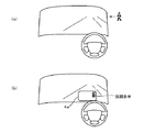
HUD4は、図2に示すように、車両10のフロントウインドウの、運転者の前方位置に画面4aが表示されるように設けられている。
The
As shown in FIG. 2, the HUD 4 is provided so that a screen 4a is displayed at a position in front of the driver in a front window of the
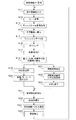
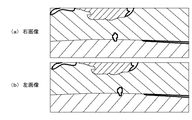
図3は画像処理ユニット2における処理の手順を示すフローチャートであり、先ずカメラ1R、1Lの出力信号をA/D変換して画像メモリに格納する(ステップS11,S12,S13)。画像メモリに格納される画像は、輝度情報を含んだグレースケール画像である。図5(a)(b)は、それぞれはカメラ1R,1Lによって得られるグレースケール画像(カメラ1Rにより右画像が得られ、カメラ1Lにより左画像が得られる)を説明するための図であり、ハッチングを付した領域は、中間階調(グレー)の領域であり、太い実線で囲んだ領域が、輝度レベルが高く(高温で)、画面上に白色として表示される対象物の領域(以下「高輝度領域」という)である。右画像と左画像では、同一の対象物の画面上の水平位置がずれて表示されるので、このずれ(視差)によりその対象物までの距離を算出することができる。
FIG. 3 is a flowchart showing the procedure of processing in the
図3のステップS14では、右画像を基準画像とし、その画像信号の2値化、すなわち、実験的に決定される輝度閾値ITHより明るい領域を「1」(白)とし、暗い領域を「0」(黒)とする処理を行う。図6に図5(a)の画像を2値化した画像を示す。この図は、ハッチングを付した領域が黒であり、太い実線で囲まれた高輝度領域が白であることを示している。 In step S14 in FIG. 3, the right image is used as a reference image, and the image signal is binarized, that is, an area brighter than an experimentally determined luminance threshold ITH is set to “1” (white), and a dark area is set to “0”. (Black). FIG. 6 shows an image obtained by binarizing the image shown in FIG. This figure shows that the hatched area is black, and the high-luminance area surrounded by the thick solid line is white.
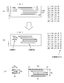
続くステップS15では、2値化した画像データをランレングスデータに変換する処理を行う。図7(a)はこれを説明するための図であり、この図では2値化により白となった領域を画素レベルでラインL1〜L8として示している。ラインL1〜L8は、いずれもy方向には1画素の幅を有しており、実際にはy方向には隙間なく並んでいるが、説明のために離間して示している。またラインL1〜L8は、x方向にはそれぞれ2画素、2画素、3画素、8画素、7画素、8画素、8画素、8画素の長さを有している。ランレングスデータは、ラインL1〜L8を各ラインの開始点(各ラインの左端の点)の座標と、開始点から終了点(各ラインの右端の点)までの長さ(画素数)とで示したものである。例えばラインL3は、(x3,y5)、(x4,y5)及び(x5,y5)の3画素からなるので、ランレングスデータとしては、(x3,y5,3)となる。 In the following step S15, a process of converting the binarized image data into run-length data is performed. FIG. 7A is a diagram for explaining this, and in this diagram, the regions that have become white due to binarization are shown as lines L1 to L8 at the pixel level. Each of the lines L1 to L8 has a width of one pixel in the y direction, and is actually arranged without a gap in the y direction, but is shown apart for the sake of explanation. The lines L1 to L8 have a length of 2 pixels, 2 pixels, 3 pixels, 8 pixels, 7 pixels, 8 pixels, 8 pixels, and 8 pixels in the x direction, respectively. The run-length data indicates the lines L1 to L8 as the coordinates of the start point of each line (the left end point of each line) and the length (the number of pixels) from the start point to the end point (the right end point of each line). It is shown. For example, since the line L3 is composed of three pixels (x3, y5), (x4, y5) and (x5, y5), the run length data is (x3, y5, 3).
ステップS16、S17では、図7(b)に示すように対象物のラベリングをすることにより、対象物を抽出する処理を行う。すなわち、ランレングスデータ化したラインL1〜L8のうち、y方向に重なる部分のあるラインL1〜L3を1つの対象物1とみなし、ラインL4〜L8を1つの対象物2とみなし、ランレングスデータに対象物ラベル1,2を付加する。この処理により、例えば図6に示す高輝度領域が、それぞれ対象物1から4として把握されることになる。
In steps S16 and S17, as shown in FIG. 7B, a process of extracting the target object is performed by labeling the target object. That is, of the lines L1 to L8 converted into run-length data, the lines L1 to L3 having a portion overlapping in the y-direction are regarded as one
ステップS18では図7(c)に示すように、抽出した対象物の重心G、面積S及び破線で示す外接四角形の縦横比ASPECTを算出する。面積Sは、ランレングスデータの長さを同一対象物について積算することにより算出し、重心Gの座標は、面積Sをx方向に2等分する線のx座標及びy方向に2等分する線のy座標として算出し、縦横比APECTは、図7(c)に示すDyとDxとの比Dy/Dxとして算出する。なお、重心Gの位置は、外接四角形の重心位置で代用してもよい。 In step S18, as shown in FIG. 7C, the center of gravity G, the area S, and the aspect ratio ASPECT of the circumscribed rectangle indicated by the broken line are calculated. The area S is calculated by integrating the length of the run-length data for the same object, and the coordinates of the center of gravity G are bisected in the x coordinate and the y direction of the line that bisects the area S in the x direction. The aspect ratio APECT is calculated as the y coordinate of the line, and the aspect ratio APECT is calculated as the ratio Dy / Dx between Dy and Dx shown in FIG. The position of the center of gravity G may be replaced by the position of the center of gravity of a circumscribed rectangle.
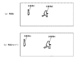
ステップS19では、対象物の時刻間追跡、すなわちサンプリング周期毎に同一対象物の認識を行う。アナログ量としての時刻tをサンプリング周期で離散化した時刻をkとし、図8(a)に示すように時刻kで対象物1,2を抽出した場合において、時刻(k+1)で抽出した対象物3,4と、対象物1,2との同一性判定を行う。具体的には、以下の同一性判定条件1)〜3)を満たすときに、対象物1、2と対象物3、4とは同一であると判定し、対象物3、4をそれぞれ1,2というラベルに変更することにより、時刻間追跡が行われる。
In step S19, the tracking of the object is performed between times, that is, the same object is recognized in each sampling cycle. The time at which the time t as the analog amount is discretized at the sampling period is k, and when the
1)時刻kにおける対象物i(=1,2)の画像上での重心位置座標を、それぞれ(xi(k),yi(k))とし、時刻(k+1)における対象物j(=3,4)の画像上での重心位置座標を、(xj(k+1),yj(k+1))としたとき、
|xj(k+1)−xi(k)|<Δx
|yj(k+1)−yi(k)|<Δy
であること。ただし、Δx、Δyは、それぞれx方向及びy方向の画像上の移動量の許容値である。
1) The coordinates of the position of the center of gravity of the object i (= 1, 2) on the image at the time k are (xi (k), yi (k)), and the object j (= 3, 3) at the time (k + 1). When the coordinates of the position of the center of gravity on the image of 4) are (xj (k + 1), yj (k + 1)),
| Xj (k + 1) -xi (k) | <Δx
| Yj (k + 1) -yi (k) | <Δy
That. Here, Δx and Δy are allowable values of the moving amount on the image in the x direction and the y direction, respectively.
2)時刻kにおける対象物i(=1,2)の画像上での面積をSi(k)とし、時刻(k+1)における対象物j(=3,4)の画像上での面積をSj(k+1)としたとき、
Sj(k+1)/Si(k)<1±ΔS
であること。ただし、ΔSは面積変化の許容値である。
2) The area of the object i (= 1, 2) on the image at time k is Si (k), and the area of the object j (= 3, 4) on the image at time (k + 1) is Sj ( k + 1),
Sj (k + 1) / Si (k) <1 ± ΔS
That. Here, ΔS is an allowable value of the area change.
3)時刻kにおける対象物i(=1,2)の外接四角形の縦横比をASPECTi(k)とし、時刻(k+1)における対象物j(=3,4)の外接四角形の縦横比をASPECTj(k+1)としたとき、
ASPECTj(k+1)/ASPECTi(k)<1±ΔASPECT
であること。ただし、ΔASPECTは縦横比変化の許容値である。
3) The aspect ratio of the circumscribed rectangle of the object i (= 1, 2) at time k is assumed to be ASPECTi (k), and the aspect ratio of the circumscribed rectangle of the object j (= 3, 4) at time (k + 1) is ASPECTj ( k + 1),
ASPECTj (k + 1) / ASPECTi (k) <1 ± ΔASPECT
That. Here, ΔASPECT is an allowable value of the aspect ratio change.
図8(a)と(b)とを対比すると、各対象物は画像上での大きさが大きくなっているが、対象物1と3とが上記同一性判定条件を満たし、対象物2と4とが上記同一性判定条件を満たすので、対象物3、4はそれぞれ対象物1、2と認識される。このようにして認識された各対象物の(重心の)位置座標は、時系列位置データとしてメモリに格納され、後の演算処理に使用される。
なお以上説明したステップS14〜S19の処理は、2値化した基準画像(本実施形態では、右画像)ついて実行する。
8A and 8B, each object has a large size on the image, but the
The processes in steps S14 to S19 described above are executed for the binarized reference image (the right image in the present embodiment).
図3のステップS20では、車速センサ6により検出される車速VCAR及びヨーレートセンサ5より検出されるヨーレートYRを読み込み、ヨーレートYRを時間積分することより、自車両10の回頭角θr(図14参照)を算出する。
In step S20 of FIG. 3, the vehicle speed VCAR detected by the
一方、ステップS31〜S33では、ステップS19,S20の処理と平行して、対象物と自車両10と距離zを算出する処理を行う。この演算はステップS19,S20より長い時間を要するため、ステップS19,S20より長い周期(例えばステップS11〜S20の実行周期の3倍程度の周期)で実行される。
On the other hand, in steps S31 to S33, processing for calculating the distance z between the target object and the
ステップS31では、基準画像(右画像)の2値化画像によって追跡される対象物の中の1つを選択することにより、図9(a)に示すように右画像から探索画像R1(ここでは、外接四角形で囲まれる領域全体を探索画像とする)を抽出する。続くステップS32では、左画像中から探索画像に対応する画像(以下「対応画像」という)を探索する探索領域を設定し、相関演算を実行して対応画像を抽出する。具体的には、探索画像R1の各頂点座標に応じて左画像中に図9(b)に示すように、探索領域R2を設定し、探索領域R2内で探索画像R1との相関の高さを示す輝度差分総和値C(a,b)を下記式(1)により算出し、この総和値C(a,b)が最小となる領域を対応画像として抽出する。なお、この相関演算は、2値画像ではなくグレースケール画像を用いて行う。また同一対象物についての過去の位置データがあるときは、その位置データに基づいて探索領域R2より狭い領域R2a(図9(b)に破線で示す)を探索領域として設定する。
ここで、IR(m,n)は、図10に示す探索画像R1内の座標(m,n)の位置の輝度値であり、IL(a+m−M,b+n−N)は、探索領域内の座標(a,b)を基点とした、探索画像R1と同一形状の局所領域R3内の座標(m,n)の位置の輝度値である。基点の座標(a,b)を変化させて輝度差分総和値C(a,b)が最小となる位置を求めることにより、対応画像の位置が特定される。 Here, IR (m, n) is a luminance value at the position of coordinates (m, n) in the search image R1 shown in FIG. 10, and IL (a + m−M, b + n−N) is a value within the search area. The luminance value at the position of the coordinates (m, n) in the local region R3 having the same shape as the search image R1 with the coordinates (a, b) as the base point. The position of the corresponding image is specified by changing the coordinates (a, b) of the base point and obtaining the position where the luminance difference total value C (a, b) is minimized.
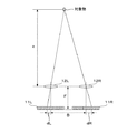
ステップS32の処理により、図11に示すように探索画像R1と、この対象物に対応する対応画像R4とが抽出されるので、ステップS33では、探索画像R1の重心位置と、画像中心線LCTRとの距離dR(画素数)及び対応画像R4の重心位置と画像中心線LCTRとの距離dL(画素数)を求め、下記式(2)に適用して、自車両10と、対象物との距離zを算出する。
ここで、Bは基線長、すなわち図12に示すようにカメラ1Rの撮像素子11Rの中心位置と、カメラ1Lの撮像素子11Lの中心位置との水平方向(x方向)の距離(両カメラの光軸の間隔)、Fはレンズ12R、12Lの焦点距離、pは、撮像素子11R、11L内の画素間隔であり、Δd(=dR+dL)が視差量である。
Here, B is the base line length, that is, the distance in the horizontal direction (x direction) between the center position of the
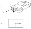
ステップS21では、画像内の座標(x,y)及び式(2)により算出した距離zを下記式(3)に適用し、実空間座標(X,Y,Z)に変換する。ここで、実空間座標(X,Y,Z)は、図13(a)に示すように、カメラ1R、1Lの取り付け位置の中点の位置(自車両10に固定された位置)を原点Oとして、図示のように定め、画像内の座標は同図(b)に示すように、画像の中心を原点として水平方向をx、垂直方向をyと定めている。
ここで、(xc,yc)は、右画像上の座標(x,y)を、カメラ1Rの取り付け位置と、実空間原点Oとの相対位置関係に基づいて、実空間原点Oと画像の中心とを一致させた仮想的な画像内の座標に変換したものである。またfは、焦点距離Fと画素間隔pとの比である。
Here, (xc, yc) represents the coordinates (x, y) on the right image with the center of the real space O and the center of the image based on the relative positional relationship between the mounting position of the
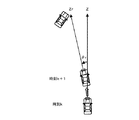
ステップS22では、自車両10が回頭することによる画像上の位置ずれを補正するための回頭角補正を行う。図14に示すように、時刻kから(k+1)までの期間中に自車両が例えば左方向に回頭角θrだけ回頭すると、カメラによって得られる画像上では、図15に示すようにΔxだけx方向にずれるので、これを補正する処理である。具体的には、下記式(4)に実空間座標(X,Y,Z)を適用して、補正座標(Xr,Yr,Zr)を算出する。算出した実空間位置データ(Xr,Yr,Zr)は、対象物毎に対応づけてメモリに格納する。なお、以下の説明では、回頭角補正後の座標を(X,Y,Z)と表示する。
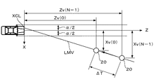
ステップS23では、図16に示すように同一対象物について、ΔTの期間内に得られた、回頭角補正後のN個の実空間位置データ(例えばN=10程度)、すなわち時系列データから、対象物と自車両10との相対移動ベクトルに対応する近似直線LMVを求める。具体的には、近似直線LMVの方向を示す方向ベクトルL=(lx,ly,lz)(|L|=1)とすると、下記式(5)で表される直線を求める。
ここでuは、任意の値をとる媒介変数であり、Xav,Yav及びZavは、それぞれ実空間位置データ列のX座標の平均値、Y座標の平均値及びZ座標の平均値である。なお、式(5)は媒介変数uを消去すれば下記式(5a)のようになる。
(X−Xav)/lx=(Y−Yav)/ly=(Z−Zav)/lz
…(5a)
Here, u is a parameter that takes an arbitrary value, and Xav, Yav, and Zav are the average value of the X coordinate, the average value of the Y coordinate, and the average value of the Z coordinate of the real space position data sequence, respectively. The equation (5) becomes the following equation (5a) if the parameter u is eliminated.
(X-Xav) / lx = (Y-Yav) / ly = (Z-Zav) / lz
… (5a)
図16は、近似直線LMVを説明するための図であり、同図のP(0),P(1),P(2),…,P(N−2),P(N−1)が回頭角補正後の時系列データを示し、近似直線LMVは、この時系列データの平均位置座標Pav(=(Xav,Yav,Zav))を通り、各データ点からの距離の2乗の平均値が最小となるような直線として求められる。ここで各データ点の座標を示すPに付した()内の数値はその値が増加するほど過去のデータであることを示す。例えば、P(0)は最新の位置座標、P(1)は1サンプル周期前の位置座標、P(2)は2サンプル周期前の位置座標を示す。以下の説明におけるD(j)、X(j)、Y(j)、Z(j)等も同様である。 FIG. 16 is a diagram for explaining the approximate straight line LMV, in which P (0), P (1), P (2),..., P (N-2), P (N-1) The time series data after the turning angle correction is shown, and the approximate straight line LMV passes through the average position coordinates Pav (= (Xav, Yav, Zav)) of the time series data, and is the average value of the square of the distance from each data point. Is obtained as a straight line that minimizes. Here, the numerical value in parentheses attached to P indicating the coordinates of each data point indicates that the larger the value is, the more past the data is. For example, P (0) indicates the latest position coordinates, P (1) indicates the position coordinates one sample cycle ago, and P (2) indicates the position coordinates two sample cycles ago. The same applies to D (j), X (j), Y (j), Z (j) and the like in the following description.
より具体的には、平均位置座標Pavから各データ点の座標P(0)〜P(N−1)に向かうベクトルD(j)=(DX(j),DY(j),DZ(j))=(X(j)−Xav,Y(j)−Yav,Z(j)−Zav)と、方向ベクトルLとの内積sを下記式(6)により算出し、この内積sの分散が最大となる方向ベクトルL=(lx,ly,lz)を求める。
s=lx・DX(j)+ly・DY(j)+lz・DZ(j) (6)
More specifically, a vector D (j) = (DX (j), DY (j), DZ (j) from the average position coordinates Pav to the coordinates P (0) to P (N-1) of each data point. ) = (X (j) -Xav, Y (j) -Yav, Z (j) -Zav) and the inner product s of the direction vector L are calculated by the following equation (6), and the variance of the inner product s is the maximum. A direction vector L = (lx, ly, lz) is obtained.
s = lx.DX (j) + ly.DY (j) + lz.DZ (j) (6)
各データ点の座標の分散共分散行列Vは、下記式(7)で表され、この行列の固有値σが内積sの分散に相当するので、この行列から算出される3つの固有値のうち最大の固有値に対応する固有ベクトルが求める方向ベクトルLとなる。なお、式(7)の行列から固有値と固有ベクトルを算出するには、ヤコビ法(例えば「数値計算ハンドブック」(オーム社)に示されている)として知られている手法を用いる。
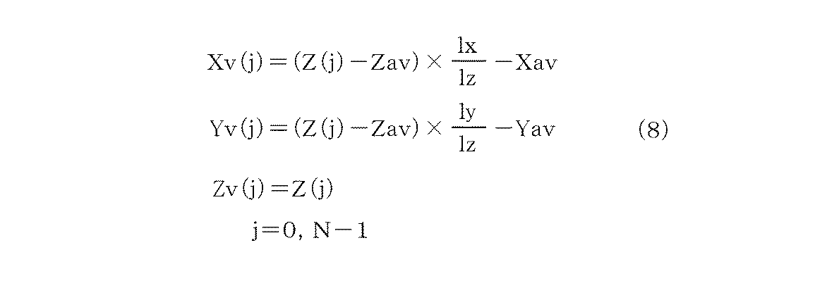
次いで最新の位置座標P(0)=(X(0),Y(0),Z(0))と、(N−1)サンプル前(時間ΔT前)の位置座標P(Nー1)=(X(N−1),Y(N−1),Z(N−1))を近似直線LMV上の位置に補正する。具体的には、前記式(5a)にZ座標Z(0)、Z(N−1)を適用することにより、すなわち下記式(8)により、補正後の位置座標Pv(0)=(Xv(0),Yv(0),Zv(0))及びPv(N−1)=(Xv(N−1),Yv(N−1),Zv(N−1))を求める。
式(8)で算出された位置座標Pv(N−1)からPv(0)に向かうベクトルとして、相対移動ベクトルが得られる。このようにモニタ期間ΔT内の複数(N個)のデータから対象物の自車両10に対する相対移動軌跡を近似する近似直線を算出して相対移動ベクトルを求めることにより、位置検出誤差の影響を軽減して対象物との衝突の可能性をより正確に予測することが可能となる。
相 対 A relative movement vector is obtained as a vector from the position coordinates Pv (N−1) calculated by the equation (8) to Pv (0). In this way, the influence of the position detection error is reduced by calculating the approximate straight line that approximates the relative movement trajectory of the target object with respect to the
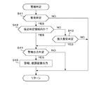
図3に戻り、ステップS24では、検出した対象物との衝突の可能性を判定し、その可能性が高いときに警報を発する警報判定処理(図4)を実行する。
ステップS41では、下記式(9)によりZ方向の相対速度Vsを算出し、下記式(10)及び(11)が成立するとき、衝突の可能性があると判定してステップS42に進み、式(10)及び/または式(11)が不成立のときは、この処理を終了する。
Vs=(Zv(N−1)−Zv(0))/ΔT (9)
Zv(0)/Vs≦T (10)
|Yv(0)|≦H (11)
Returning to FIG. 3, in step S24, the possibility of collision with the detected object is determined, and an alarm determination process (FIG. 4) for issuing an alarm when the possibility is high is executed.
In step S41, the relative velocity Vs in the Z direction is calculated by the following equation (9). When the following equations (10) and (11) are satisfied, it is determined that there is a possibility of a collision, and the process proceeds to step S42. When (10) and / or Expression (11) are not satisfied, this processing ends.
Vs = (Zv (N−1) −Zv (0)) / ΔT (9)
Zv (0) / Vs ≦ T (10)
| Yv (0) | ≦ H (11)
ここで、Zv(0)は最新の距離検出値(vは近似直線LMVによる補正後のデータであることを示すために付しているが、Z座標は補正前と同一の値である)であり、Zv(N−1)は、時間ΔT前の距離検出値である。またTは、余裕時間であり、衝突の可能性を予測衝突時刻より時間Tだけ前に判定することを意図したものであり、例えば2〜5秒程度に設定される。またHは、Y方向、すなわち高さ方向の範囲を規定する所定高さであり、例えば自車両10の車高の2倍程度に設定される。
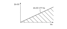
式(10)の関係を図示すると図17に示すようになり、検出した相対速度Vsと距離Zv(0)とに対応する座標が、ハッチングを付した領域にあり、かつ|Yv(0)|≦Hであるとき、ステップS42以下の判定が実行される。
Here, Zv (0) is the latest distance detection value (v is added to indicate that the data has been corrected by the approximate straight line LMV, but the Z coordinate is the same value as before the correction). Yes, Zv (N-1) is the distance detection value before the time ΔT. T is a margin time, which is intended to determine the possibility of collision by the time T before the predicted collision time, and is set to, for example, about 2 to 5 seconds. H is a predetermined height that defines a range in the Y direction, that is, the height direction, and is set to, for example, about twice the height of the
FIG. 17 shows the relationship of Expression (10), where the coordinates corresponding to the detected relative speed Vs and the distance Zv (0) are in the hatched area, and | Yv (0) | When ≦ H, the determination in step S42 and subsequent steps is performed.
図18は、カメラ1R、1Lで監視可能な領域を、太い実線で示す外側の三角形の領域AR0で示し、さらに領域AR0内の、Z1=Vs×Tより自車両10に近い領域AR1,AR2,AR3を、警報判定領域としている。ここで領域AR1は、自車両10の車幅αの両側に余裕β(例えば50〜100cm程度とする)を加えた範囲に対応する領域、換言すれば自車両10の横方向の中心軸の両側に(α/2+β)の幅を有する領域であって、対象物がそのまま存在し続ければ衝突の可能性がきわめて高いので、接近判定領域と呼ぶ。領域AR2,AR3は、接近判定領域よりX座標の絶対値が大きい(接近判定領域の横方向外側の)領域であり、この領域内にある対象物については、後述する侵入衝突判定を行うので、侵入判定領域と呼ぶ。なおこれらの領域は、前記式(11)に示したようにY方向には、所定高さHを有する。
FIG. 18 shows an area that can be monitored by the
前記ステップS41の答が肯定(YES)となるのは、対象物が接近判定領域AR1または侵入判定領域AR2,AR3のいずれかに存在する場合である。
続くステップS42では、対象物が接近判定領域AR1内にあるか否かを判別し、この答が肯定(YES)であるときは、直ちにステップS44に進む一方、否定(NO)であるときは、ステップS43で侵入衝突判定を行う。具体的には、画像上での最新のx座標xc(0)(cは前述したように画像の中心位置を実空間原点Oに一致させる補正を行った座標であることを示すために付している)と、時間ΔT前のx座標xc(N−1)との差が下記式(12)を満たすか否かを判別し、満たす場合に衝突の可能性が高いと判定する。
In a succeeding step S42, it is determined whether or not the object is in the approach determination area AR1. When the answer is affirmative (YES), the process proceeds to step S44 immediately, while when the answer is negative (NO), In step S43, an intrusion collision determination is performed. Specifically, the latest x coordinate xc (0) on the image (c is added to indicate that the coordinate has been corrected so that the center position of the image coincides with the real space origin O as described above. Is determined) and the difference between the x coordinate xc (N−1) before the time ΔT satisfies the following expression (12), and if so, it is determined that the possibility of collision is high.
図19に示すように、自車両10の進行方向に対してほぼ90°の方向から進行してくる動物20がいた場合、Xv(Nー1)/Zv(N−1)=Xv(0)/Zv(0)であるとき、換言すれば動物の速度Vpと相対速度Vsの比Vp/Vs=Xv(Nー1)/Zv(N−1)であるとき、自車両10から動物20と見る方位角θdは一定となり、衝突の可能性が高い。式(12)は、この可能性を自車両10の車幅αを考慮して判定するものである。以下図20を参照して式(12)の導出手法を説明する。
As shown in FIG. 19, when there is an
対象物20の最新の位置座標と時間ΔT前の位置座標と通る直線、すなわち近似直線LMVとXY平面(X軸とY軸とを含む平面、すなわち車両10の先端部に対応する線(X軸)を含み車両10の進行方向に垂直な面)との交点のX座標をXCLとすると、車幅αを考慮した衝突発生の条件は、下記式(13)で与えられる。
A straight line passing through the latest position coordinates of the
−α/2≦XCL≦α/2 (13)
一方近似直線LMVをXZ平面に投影した直線は、下記式(14)で与えられる。
On the other hand, a straight line obtained by projecting the approximate straight line LMV on the XZ plane is given by the following equation (14).
また実空間座標Xと、画像上の座標xcとは、前記式(3)に示した関係があるので、
Xv(0)=xc(0)×Zv(0)/f (16)
Xv(N−1)=xc(N−1)×Zv(N−1)/f (17)
であり、これらを式(15)に適用すると、交点X座標XCLは下記式(18)で与えられる。これを式(13)に代入して整理することにより、式(12)の条件が得られる。
Xv (0) = xc (0) × Zv (0) / f (16)
Xv (N−1) = xc (N−1) × Zv (N−1) / f (17)
When these are applied to the equation (15), the intersection X coordinate XCL is given by the following equation (18). By substituting this into equation (13) and rearranging, the condition of equation (12) is obtained.
図4に戻り、ステップS43で衝突の可能性が高いと判定したときは、ステップS44に進み、低いと判定したときは本処理を終了する。
ステップS44では、以下のようにして警報出力判定、すなわち警報出力を行うか否かの判定を行う。先ずブレーキセンサ7の出力から自車両10の運転者がブレーキ操作を行っているか否かを判別し、ブレーキ操作を行っていなければ直ちにステップS45に進んで、警報出力を行う。ブレーキ操作を行っている場合には、それによって発生する加速度Gs(減速方向を正とする)を算出し、この加速度Gsが所定閾値GTH以下であるときは、ステップS45に進む一方、Gx>GTHであるときは、ブレーキ操作により衝突が回避されると判定して本処理を終了する。これにより、適切なブレーキ操作が行われているときは、警報を発しないようにして、運転者に余計な煩わしさを与えないようにすることができる。
Returning to FIG. 4, when it is determined in step S43 that the possibility of collision is high, the process proceeds to step S44, and when it is determined that the collision is low, the process ends.
In step S44, an alarm output determination, that is, a determination as to whether or not to output an alarm is performed as follows. First, it is determined from the output of the
所定閾値GTHは、下記式(19)のように定める。これは、ブレーキ加速度Gsがそのまま維持された場合に、距離Zv(0)以下の走行距離で自車両10が停止する条件に対応する値である。
以上のように本実施形態では、同一対象物についての時系列の複数の位置データに基づいてその対象物の実空間での位置を算出し、その実空間位置から移動ベクトルを算出し、そのようにして算出された移動ベクトルに基づいて対象物と自車両10との衝突の可能性を判定するようにしたので、従来の装置のような誤判定が発生することがなく、衝突可能性の判定精度を向上させることができる。
また、対象物の相対移動軌跡を近似する近似直線LMVを求め、検出位置がこの近似直線上の位置するように位置座標を補正し、補正後の位置座標から移動ベクトルを求めるようにしたので、検出位置の誤差の影響を軽減してより正確な衝突可能性の判定を行うことができる。
また車幅αを考慮した衝突判定を行うようにしたので、衝突の可能性を正確に判定し、無用の警報を発することを防止することができる。
As described above, in the present embodiment, the position of the target in the real space is calculated based on a plurality of time-series position data of the same target, and the movement vector is calculated from the position of the real space. The possibility of collision between the target object and the
Further, an approximate straight line LMV approximating the relative movement locus of the target object is obtained, the position coordinates are corrected so that the detected position is located on this approximate straight line, and the movement vector is obtained from the corrected position coordinates. The influence of the error in the detection position can be reduced, and the possibility of collision can be determined more accurately.
In addition, since the collision is determined in consideration of the vehicle width α, it is possible to accurately determine the possibility of the collision and prevent the unnecessary warning from being issued.
本実施形態では、画像処理ユニット2が、相対位置検出手段、実空間位置算出手段、判定手段、及び警報手段の一部を構成する。より具体的には、図3のステップS14〜S19が相対位置検出手段に相当し、ステップS20〜S23が実空間位置算出手段に相当し、図4のステップS41〜S44が判定手段に相当し、同図のステップS45並びにスピーカ3及びHUD4が警報手段に相当する。
In the present embodiment, the
なお本発明は上述した実施形態に限るものではなく、種々の変形が可能である。例えば、本実施形態では、撮像手段として赤外線カメラを使用したが、例えば特開平9−226490号公報に示されるように通常の可視光線のみ検出可能なテレビカメラを使用してもよい。ただし、赤外線カメラを用いることにより、動物あるいは走行中の車両などの抽出処理を簡略化することができ、演算装置の演算能力が比較的低いものでも実現できる。
また上述した実施形態では、車両の前方を監視する例を示したが、車両の後方などいずれの方向を監視するようにしてもよい。
The present invention is not limited to the embodiment described above, and various modifications are possible. For example, in the present embodiment, an infrared camera is used as the image pickup means. However, for example, a television camera that can detect only ordinary visible light may be used as shown in Japanese Patent Application Laid-Open No. 9-226490. However, the use of an infrared camera can simplify the process of extracting an animal, a running vehicle, and the like, and can realize even an arithmetic device having a relatively low arithmetic capability.
Further, in the above-described embodiment, an example in which the front of the vehicle is monitored has been described, but any direction such as the rear of the vehicle may be monitored.
1R、1L 赤外線カメラ(撮像手段)
2 画像処理ユニット(相対位置検出手段、実空間位置算出手段、判定手段、警報手段)
3 スピーカ(警報手段)
4 ヘッドアップディスプレイ(警報手段)
5 ヨーレートセンサ
6 車速センサ
7 ブレーキセンサ
1R, 1L infrared camera (imaging means)
2 Image processing unit (relative position detecting means, real space position calculating means, determining means, alarm means)
3 Speaker (alarm means)
4 Head-up display (alarm means)
5
Claims (2)
前記撮像手段により得られる画像から前記対象物の当該車両に対する相対位置を位置データとして検出する相対位置検出手段と、
該相対位置検出手段により検出される、前記対象物についての位置データに基づいてその対象物の実空間での位置を算出する実空間位置算出手段と、
該実空間位置算出手段により算出された前記対象物までの距離と、前記対象物の、前記車両の進行方向に対して90度の水平方向の座標との比が、ほぼ一定である場合に、前記対象物が前記車両に衝突する可能性があると判定する判定手段とを備えることを特徴とする車両の周辺監視装置。 In a vehicle periphery monitoring device that detects an object existing around the vehicle from an image obtained by an imaging unit mounted on the vehicle,
Relative position detection means for detecting the relative position of the object with respect to the vehicle from the image obtained by the imaging means as position data,
A real space position calculating unit that calculates a position of the object in a real space based on position data of the object, detected by the relative position detecting unit;
When the ratio between the distance to the object calculated by the real space position calculating means and the coordinates of the object in the horizontal direction at 90 degrees to the traveling direction of the vehicle is substantially constant, Determining means for determining that there is a possibility that the object collides with the vehicle.
Priority Applications (1)
| Application Number | Priority Date | Filing Date | Title |
|---|---|---|---|
| JP2003309717A JP3949628B2 (en) | 2003-09-02 | 2003-09-02 | Vehicle periphery monitoring device |
Applications Claiming Priority (1)
| Application Number | Priority Date | Filing Date | Title |
|---|---|---|---|
| JP2003309717A JP3949628B2 (en) | 2003-09-02 | 2003-09-02 | Vehicle periphery monitoring device |
Related Parent Applications (1)
| Application Number | Title | Priority Date | Filing Date |
|---|---|---|---|
| JP17672799A Division JP3515926B2 (en) | 1999-06-23 | 1999-06-23 | Vehicle periphery monitoring device |
Publications (2)
| Publication Number | Publication Date |
|---|---|
| JP2004103018A true JP2004103018A (en) | 2004-04-02 |
| JP3949628B2 JP3949628B2 (en) | 2007-07-25 |
Family
ID=32290713
Family Applications (1)
| Application Number | Title | Priority Date | Filing Date |
|---|---|---|---|
| JP2003309717A Expired - Fee Related JP3949628B2 (en) | 2003-09-02 | 2003-09-02 | Vehicle periphery monitoring device |
Country Status (1)
| Country | Link |
|---|---|
| JP (1) | JP3949628B2 (en) |
Cited By (8)
| Publication number | Priority date | Publication date | Assignee | Title |
|---|---|---|---|---|
| US7778770B2 (en) | 2005-03-31 | 2010-08-17 | Honda Motor Co., Ltd. | Communication system between vehicles |
| JP2012002584A (en) * | 2010-06-15 | 2012-01-05 | Yokosuka Telecom Research Park:Kk | Positioning device and method |
| CN103287337A (en) * | 2013-06-26 | 2013-09-11 | 宁夏新航信息科技有限公司 | GPS life detection system |
| DE102014217233A1 (en) | 2013-08-29 | 2015-03-05 | Denso Corporation | Collision Probability Determination Device and Program |
| CN105403187A (en) * | 2015-12-14 | 2016-03-16 | 长春轨道客车股份有限公司 | High-speed motor train unit body three-dimensional dimension detection method |
| US9418428B2 (en) | 2012-07-02 | 2016-08-16 | Nec Corporation | Position management device, position management system, position management method, and position management program |
| JP2017151726A (en) * | 2016-02-24 | 2017-08-31 | 株式会社デンソー | Collision predicting device |
| WO2020062032A1 (en) * | 2018-09-28 | 2020-04-02 | Baidu.Com Times Technology (Beijing) Co., Ltd. | A pedestrian probability prediction system for autonomous vehicles |
Citations (7)
| Publication number | Priority date | Publication date | Assignee | Title |
|---|---|---|---|---|
| JPH07105497A (en) * | 1993-10-05 | 1995-04-21 | Mitsubishi Electric Corp | Inter-vehicle distance detector |
| JPH07209418A (en) * | 1993-12-14 | 1995-08-11 | Thomson Csf | Collision prevention device for motor vehicle |
| JPH0845000A (en) * | 1994-07-28 | 1996-02-16 | Fuji Heavy Ind Ltd | Vehicle-to-vehicle distance controller |
| JPH09226490A (en) * | 1996-02-22 | 1997-09-02 | Nippon Soken Inc | Detector for crossing object |
| JPH09326032A (en) * | 1996-06-06 | 1997-12-16 | Fuji Heavy Ind Ltd | Vehicle surrounding three-dimensional object recognition device |
| JPH10143245A (en) * | 1996-11-07 | 1998-05-29 | Komatsu Ltd | Obstacle collision prevention device for moving objects |
| JPH10285582A (en) * | 1997-04-04 | 1998-10-23 | Fuji Heavy Ind Ltd | Vehicle outside monitoring device |
-
2003
- 2003-09-02 JP JP2003309717A patent/JP3949628B2/en not_active Expired - Fee Related
Patent Citations (7)
| Publication number | Priority date | Publication date | Assignee | Title |
|---|---|---|---|---|
| JPH07105497A (en) * | 1993-10-05 | 1995-04-21 | Mitsubishi Electric Corp | Inter-vehicle distance detector |
| JPH07209418A (en) * | 1993-12-14 | 1995-08-11 | Thomson Csf | Collision prevention device for motor vehicle |
| JPH0845000A (en) * | 1994-07-28 | 1996-02-16 | Fuji Heavy Ind Ltd | Vehicle-to-vehicle distance controller |
| JPH09226490A (en) * | 1996-02-22 | 1997-09-02 | Nippon Soken Inc | Detector for crossing object |
| JPH09326032A (en) * | 1996-06-06 | 1997-12-16 | Fuji Heavy Ind Ltd | Vehicle surrounding three-dimensional object recognition device |
| JPH10143245A (en) * | 1996-11-07 | 1998-05-29 | Komatsu Ltd | Obstacle collision prevention device for moving objects |
| JPH10285582A (en) * | 1997-04-04 | 1998-10-23 | Fuji Heavy Ind Ltd | Vehicle outside monitoring device |
Cited By (12)
| Publication number | Priority date | Publication date | Assignee | Title |
|---|---|---|---|---|
| US7778770B2 (en) | 2005-03-31 | 2010-08-17 | Honda Motor Co., Ltd. | Communication system between vehicles |
| JP2012002584A (en) * | 2010-06-15 | 2012-01-05 | Yokosuka Telecom Research Park:Kk | Positioning device and method |
| US9418428B2 (en) | 2012-07-02 | 2016-08-16 | Nec Corporation | Position management device, position management system, position management method, and position management program |
| CN103287337A (en) * | 2013-06-26 | 2013-09-11 | 宁夏新航信息科技有限公司 | GPS life detection system |
| DE102014217233A1 (en) | 2013-08-29 | 2015-03-05 | Denso Corporation | Collision Probability Determination Device and Program |
| US9711049B2 (en) | 2013-08-29 | 2017-07-18 | Denso Corporation | Collision probability determination apparatus and program |
| CN105403187A (en) * | 2015-12-14 | 2016-03-16 | 长春轨道客车股份有限公司 | High-speed motor train unit body three-dimensional dimension detection method |
| JP2017151726A (en) * | 2016-02-24 | 2017-08-31 | 株式会社デンソー | Collision predicting device |
| WO2020062032A1 (en) * | 2018-09-28 | 2020-04-02 | Baidu.Com Times Technology (Beijing) Co., Ltd. | A pedestrian probability prediction system for autonomous vehicles |
| CN111328411A (en) * | 2018-09-28 | 2020-06-23 | 百度时代网络技术(北京)有限公司 | Pedestrian probability prediction system for autonomous vehicle |
| JP2021501712A (en) * | 2018-09-28 | 2021-01-21 | バイドゥ ドットコム タイムス テクノロジー (ベイジン) カンパニー リミテッド | Pedestrian probability prediction system for self-driving vehicles |
| US11230297B2 (en) | 2018-09-28 | 2022-01-25 | Baidu Usa Llc | Pedestrian probability prediction system for autonomous vehicles |
Also Published As
| Publication number | Publication date |
|---|---|
| JP3949628B2 (en) | 2007-07-25 |
Similar Documents
| Publication | Publication Date | Title |
|---|---|---|
| JP3515926B2 (en) | Vehicle periphery monitoring device | |
| JP4615139B2 (en) | Vehicle periphery monitoring device | |
| JP3739693B2 (en) | Image recognition device | |
| JP3764086B2 (en) | Vehicle information providing device | |
| JP5503728B2 (en) | Vehicle periphery monitoring device | |
| US8144195B2 (en) | Vehicle zone monitoring apparatus | |
| JP4410292B1 (en) | Vehicle periphery monitoring device | |
| WO2011108198A1 (en) | Surrounding area monitoring device for vehicle | |
| JP2001169310A (en) | Distance detection device | |
| JP3919975B2 (en) | Vehicle periphery monitoring device | |
| JP3916930B2 (en) | Approach warning device | |
| JP3949628B2 (en) | Vehicle periphery monitoring device | |
| JP2009075124A (en) | Distance detector | |
| JP3910345B2 (en) | Position detection device | |
| JP2010089661A (en) | Vehicle periphery monitoring device | |
| JP4943403B2 (en) | Vehicle periphery monitoring device | |
| JP4176558B2 (en) | Vehicle periphery display device | |
| JP4567072B2 (en) | Vehicle periphery monitoring device | |
| JP3961269B2 (en) | Obstacle alarm device | |
| JP2002005656A (en) | Position detection device | |
| JP3859429B2 (en) | Moving object detection device | |
| JP4040657B2 (en) | Moving object detection device | |
| JP2003309843A (en) | Obstacle warning device |
Legal Events
| Date | Code | Title | Description |
|---|---|---|---|
| A621 | Written request for application examination |
Free format text: JAPANESE INTERMEDIATE CODE: A621 Effective date: 20040729 |
|
| A977 | Report on retrieval |
Free format text: JAPANESE INTERMEDIATE CODE: A971007 Effective date: 20051102 |
|
| A131 | Notification of reasons for refusal |
Free format text: JAPANESE INTERMEDIATE CODE: A131 Effective date: 20051227 |
|
| A521 | Request for written amendment filed |
Free format text: JAPANESE INTERMEDIATE CODE: A523 Effective date: 20060220 |
|
| A131 | Notification of reasons for refusal |
Free format text: JAPANESE INTERMEDIATE CODE: A131 Effective date: 20070109 |
|
| A521 | Request for written amendment filed |
Free format text: JAPANESE INTERMEDIATE CODE: A523 Effective date: 20070302 |
|
| TRDD | Decision of grant or rejection written | ||
| A01 | Written decision to grant a patent or to grant a registration (utility model) |
Free format text: JAPANESE INTERMEDIATE CODE: A01 Effective date: 20070403 |
|
| A61 | First payment of annual fees (during grant procedure) |
Free format text: JAPANESE INTERMEDIATE CODE: A61 Effective date: 20070418 |
|
| R150 | Certificate of patent or registration of utility model |
Free format text: JAPANESE INTERMEDIATE CODE: R150 |
|
| FPAY | Renewal fee payment (event date is renewal date of database) |
Free format text: PAYMENT UNTIL: 20110427 Year of fee payment: 4 |
|
| FPAY | Renewal fee payment (event date is renewal date of database) |
Free format text: PAYMENT UNTIL: 20110427 Year of fee payment: 4 |
|
| FPAY | Renewal fee payment (event date is renewal date of database) |
Free format text: PAYMENT UNTIL: 20130427 Year of fee payment: 6 |
|
| FPAY | Renewal fee payment (event date is renewal date of database) |
Free format text: PAYMENT UNTIL: 20130427 Year of fee payment: 6 |
|
| FPAY | Renewal fee payment (event date is renewal date of database) |
Free format text: PAYMENT UNTIL: 20140427 Year of fee payment: 7 |
|
| LAPS | Cancellation because of no payment of annual fees |