JP2004106979A - Belt sling - Google Patents
Belt sling Download PDFInfo
- Publication number
- JP2004106979A JP2004106979A JP2002269898A JP2002269898A JP2004106979A JP 2004106979 A JP2004106979 A JP 2004106979A JP 2002269898 A JP2002269898 A JP 2002269898A JP 2002269898 A JP2002269898 A JP 2002269898A JP 2004106979 A JP2004106979 A JP 2004106979A
- Authority
- JP
- Japan
- Prior art keywords
- link
- belt sling
- branch
- links
- tubular member
- Prior art date
- Legal status (The legal status is an assumption and is not a legal conclusion. Google has not performed a legal analysis and makes no representation as to the accuracy of the status listed.)
- Granted
Links
- 239000000835 fiber Substances 0.000 claims abstract description 14
- 239000000725 suspension Substances 0.000 description 8
- 230000008878 coupling Effects 0.000 description 3
- 238000010168 coupling process Methods 0.000 description 3
- 238000005859 coupling reaction Methods 0.000 description 3
- 239000004952 Polyamide Substances 0.000 description 2
- 229920001778 nylon Polymers 0.000 description 2
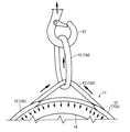
- 229920002647 polyamide Polymers 0.000 description 2
- 229920000728 polyester Polymers 0.000 description 2
- 230000015572 biosynthetic process Effects 0.000 description 1
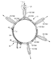
- 230000000694 effects Effects 0.000 description 1
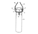
- 230000002349 favourable effect Effects 0.000 description 1
Images


Landscapes
- Load-Engaging Elements For Cranes (AREA)
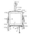
Abstract
Description
【0001】
【発明の属する技術分野】
本発明は、ベルトスリング、詳しくは、繊維製のベルトスリングに関する。
【0002】
【従来の技術】
従来より、荷役作業においては、繊維製のベルトスリングが広く使用されている。ベルトスリングは、たとえば、特開平11−43280号公報に記載されるように、その両端にリング状のアイ部が設けられており、荷役作業においては、たとえば、ベルトスリングを荷物に掛け回すとともに、両端のアイ部にフックなどを引っ掛ける、いわゆるバスケット吊りなどによって荷物を吊り上げるようにしている。
【0003】
また、バスケット吊りでは、ベルトスリングを荷物に十分に掛け回すことができないため、たとえば、図12に示すように、ベルトスリング1を荷物2に掛け回すとともに、一方のアイ部3に他方のアイ部3を通して、その他方のアイ部3にフック5などを引っ掛ける、いわゆるチョーク吊りによって吊り上げることもよく実施されている。また、このようなベルトスリングとして、繊維からなる複数のリンクを連鎖状に連結して、ベルトスリングをチェーン状に形成してなるものが知られている。
【0004】
【特許文献1】
特開平11−43280号公報
【発明が解決しようとする課題】
しかし、上記したチョーク吊りによって、荷物を吊り上げると、一方のアイ部3に他方のアイ部3が挿通された部分と荷物2との間に、略三角形の隙間が生じて、安定した吊り上げ作業を確保できないという不具合がある。
【0005】
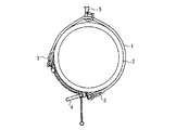
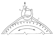
また、たとえば、図13に示すように、ベルトスリング1を荷物2に掛け回すとともに、両端のアイ部3をチェーンレバーホイスト4などにより緊張することによって荷締め、これを吊り上げるようにしても、図14に示すように、フック5により引っ掛けられるベルトスリング1が、フック5の吊り上げ方向に引っ張られ、荷物2とベルトスリング1との間に略三角形の隙間が生じて、安定した吊り上げ作業を確保できないという不具合がある。
【0006】
とりわけ、荷物2が水平方向に支持される状態(横吊り)で吊り上げる場合には、上記の隙間が生じても安定した吊り上げを確保できる場合があるが、荷物2が鉛直方向に支持される状態(縦吊り)で吊り上げる場合には、そのような隙間があると、荷物2がベルトスリング1から滑って抜け落ちるおそれを生じる。
【0007】
本発明は、このような不具合を解決するためになされたものであり、その目的とするところは、安定した吊り上げ作業を確保することのできる、ベルトスリングを提供することにある。
【0008】
【課題を解決するための手段】
上記の目的を達成するため、請求項1に記載の発明は、繊維製のベルトスリングであって、連鎖状に連結されている複数の連結リンクと、前記連結リンクの少なくとも1つに連結されている分岐リンクとを備えていることを特徴としている。
【0009】
このような構成によると、たとえば、ベルトスリングを荷物に掛け回して、荷締めた後、吊り具によって吊り上げる場合には、吊り具を分岐リンクに引っ掛けて吊り上げれば、分岐リンクが吊り具の吊り上げ方向に引っ張られ、つまり、連結リンクを直接吊り具で吊り上げないため、荷物とベルトスリングとの間に略三角形の隙間が生じることを防止することができる。そのため、安定した吊り上げ作業を確保することができる。
【0010】
また、請求項2に記載の発明は、請求項1に記載の発明において、前記ベルトスリングが荷物に掛け回された状態で前記分岐リンクを引っ張ると、前記分岐リンクが連結されている連結リンクの両側の連結リンクが互いに近接する方向に移動して、前記荷物が巻締められるように、前記分岐リンクが前記連結リンクに連結されていることを特徴としている。
【0011】
このような構成によると、たとえば、ベルトスリングを荷物に掛け回して、荷締めた後、吊り具を分岐リンクに引っ掛けて吊り上げれば、分岐リンクが吊り具の吊り上げ方向に引っ張られ、それによって、分岐リンクが連結されている連結リンクの両側の連結リンクが互いに近接する方向に移動して、荷物が巻締められる。そのため、このベルトスリングでは、吊り具によって分岐リンクを吊り上げれば、荷物が巻締められながら吊り上げられるので、より安定した吊り上げ作業を確保することができる。
【0012】
また、請求項3に記載の発明は、請求項1または2に記載の発明において、前記連結リンクのそれぞれに、前記分岐リンクが連結されていることを特徴としている。
【0013】
このような構成によると、連結リンクのそれぞれに分岐リンクが連結されているので、作業環境に応じた任意の角度から任意の分岐リンクを吊り上げることができる。そのため、吊り上げ作業の容易化、効率化を図ることができる。
【0014】
【発明の実施の形態】
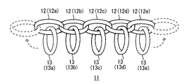
図1は、本発明のベルトスリングの一実施形態を示す側面図、図2および図3は、ベルトスリングの使用態様を説明する側面図である。
【0015】
図1において、このベルトスリング11は、繊維製からなり、連鎖状に連結されている複数の連結リンク12と、連結リンク12のそれぞれに連結されている複数の分岐リンク13とを備えている。
【0016】
各連結リンク12は、ポリエステル繊維、ナイロン繊維、ポリアミド繊維など、好ましくは、ポリエステル繊維からなる厚みのある可撓性の帯状繊維が、長円環をなすリング状に形成されている。
【0017】
各連結リンク12は、一方の連結リンク12の内側に他方の連結リンク12の内側が入り込むように、連鎖状に複数(本実施形態では5つ、以下、互いに区別する場合には、図1における左側より、第1連結リンク12a、第2連結リンク12b、第3連結リンク12c、第4連結リンク12d、第5連結リンク12eとする。)連結されている。
【0018】
各分岐リンク13は、連結リンク12と同様に、ナイロン繊維やポリアミド繊維などからなる厚みのある可撓性の帯状繊維が、長円環をなすリング状に形成されている。各分岐リンク13は、各連結リンク12の内側に、それに対応する分岐リンク13の内側が入り込むように、各連結リンク12に対応してそれぞれ(本実施形態では5つ、以下、互いに区別する場合には、図1における左側より、第1分岐リンク13a、第2分岐リンク13b、第3分岐リンク13c、第4分岐リンク13d、第5分岐リンク13eとする。)連結されている。
【0019】
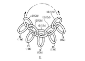
そして、このようなベルトスリング11では、図2に示すように、たとえば、両端の第1連結リンク12aと第5連結リンク12eとを把持すれば、第1連結リンク12aないし第5連結リンク12eが直線状に伸びるとともに、第1分岐リンク13aないし第5分岐リンク13eがフリー状態となる。これによって、5つの連結リンク12が連結される長さにおいて、5つの分岐リンク13が使用可能な状態となる。
【0020】
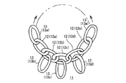
また、図3に示すように、たとえば、両端の第1分岐リンク13aと第5分岐リンク13eとを把持すれば、両端の第1分岐リンク13aおよび第5分岐リンク13eと、その間に挟まれる第1連結リンク12aないし第5連結リンク12eとが直線状に伸びるとともに、第2分岐リンク13bないし第4分岐リンク13dがフリー状態となる。これによって、2つの分岐リンク13および5つの連結リンク12(合計7つ)が連結される長さにおいて、3つの分岐リンク13が使用可能な状態となる。
【0021】
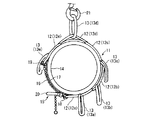
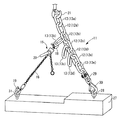
そして、このようなベルトスリング11を用いて、たとえば、図4および図5に示すように、パイプなどの円管状の管状部材14を吊り上げる場合には、まず、管状部材14の外周にベルトスリング11を掛け回し、次いで、両端の連結リンク12(第1連結リンク12aおよび第5連結リンク12e)を、緊張装置として、たとえば、チェーンレバーホイスト15などを用いて緊張することにより、ベルトスリング11によって管状部材14を荷締める。
【0022】
管状部材14の荷締は、ベルトスリング11が掛け回された状態における管状部材14の外周の両端の連結リンク12(第1連結リンク12aおよび第5連結リンク12e)の間に、まず、チェーンレバーホイスト15のチェーン16の管状部材14への当接による損傷を防止すべく、ゴムマット17を被覆する。次いで、一方の連結リンク12(第1連結リンク12a)にチェーンレバーホイスト15の上フック18を引っ掛けるとともに、他方の連結リンク12(第5連結リンク12e)にチェーンレバーホイスト15の下フック19を引っ掛ける。そして、チェーンレバーホイスト15のレバー20を緊張方向に回動させれば、両端の連結リンク12(第1連結リンク12aおよび第5連結リンク12e)が、互いに近接する方向に引き寄せられるので、その結果、ベルトスリング11によって管状部材14が荷締められる。
【0023】
そして、このようにして荷締められた管状部材14を吊り上げるには、任意の分岐リンク13(第4分岐リンク13d)に、吊り具として、たとえば、クレーン(図示せず。)のフック21を引っ掛けて吊り上げればよい。
【0024】
このようにして吊り上げれば、図5に示すように、分岐リンク13(第4分岐リンク13d)がフック21の吊り上げ方向に引っ張られ、つまり、連結リンク12(第4連結リンク12d)を直接フック21で吊り上げないため、管状部材14とベルトスリング11との間に略三角形の隙間が生じることを防止することができる。そのため、安定した吊り上げ作業を確保することができる。
【0025】
また、分岐リンク13(第4分岐リンク13d)がフック21により引っ張られるので、図5に示すように、その分岐リンク13(第4分岐リンク13d)が連結されている連結リンク12(第4連結リンク12d)の両側の連結リンク12(第3連結リンク12cおよび第5連結リンク12e)が、互いに近接する方向に移動して、管状部材14がベルトスリング11に巻締められるようになる。そのため、このベルトスリング11では、フック21によって分岐リンク13(第4分岐リンク13d)を吊り上げれば、管状部材14が巻締められながら吊り上げられるので、より安定した吊り上げ作業を確保することができる。
【0026】
そして、実際に管状部材14を吊り上げるには、たとえば、図6に示すように、まず、管状部材14の長手方向における互いに所定間隔を隔てた位置において、2つのベルトスリンク11を、上記したように掛け回して、チェーンレバーホイスト15によって荷締め、次いで、2つのベルトスリング11の分岐リンク13に、一方にカップリング23が設けられているチェーン24の他方に設けられているフック21を、それぞれ引っ掛けて、そのチェーン24の一方に設けられているカップリング23を、マスターリンク22を介してクレーン(図示せず。)のフック25に引っ掛けるようにして、管状部材14が水平方向に支持される状態(横吊り)で吊り上げればよい。
【0027】
また、このベルトスリング11では、連結リンク12のそれぞれに分岐リンク13が連結されているので、図7に示すように、管状部材14の周方向における任意の角度から、作業環境に応じて、任意の分岐リンク13を吊り上げることができる。そのため、吊り上げ作業の容易化、効率化を図ることができる。
【0028】
とりわけ、このベルトスリング11を用いれば、たとえば、図8や図9に示すように、管状部材14の長手方向一端部に1つのベルトスリング11を、上記したように掛け回して、チェーンレバーホイスト15によって荷締め、次いで、ベルトスリング11の分岐リンク13にフック21を引っ掛けて、管状部材14が鉛直方向に支持される状態(縦吊り)で吊り上げても、ベルトスリング11によって管状部材14が巻締められながら吊り上げられるので、管状部材14がベルトスリング11から滑って抜け落ちることを防止することができ、安定した吊り上げ作業を確保することができる。
【0029】
なお、図8には、ベルトスリング11の1つの分岐リンク13に1つのフック21を引っ掛ける1本吊りの態様が示されており、図9には、ベルトスリング11の2つの分岐リンク13に互いに180°変位した対向位置において、2つのフック21を対向状に引っ掛ける2本吊りの態様が示されている。また、このような縦吊りは、上記の実施形態に限らず、ベルトスリング11の3つの分岐リンク13に3つのフック21をそれぞれ引っ掛ける3本吊りや、ベルトスリング11の4つの分岐リンク13に4つのフック21をそれぞれ引っ掛ける4本吊りなど、その目的および用途によって、適宜の本数で吊り上げることができ、本数を多くする程、分岐リンク13およびフック21の1本あたりの負荷を低減することができる。
【0030】
また、上記の説明では、このベルトスリング11の使用態様の一例として、管状部材14の吊り上げについて説明したが、このベルトスリング11は、何ら制限されることなく、公知のベルトスリング(繊維スリングとも呼ばれる。)と同様の使用態様(荷物の吊り上げの他、荷物の横引き、荷締、固縛など)で用いることができる。
【0031】
たとえば、図10に示すように、円管状の管状部材14ではなく、断面矩形状の角コラム26などを吊り上げることもできる。すなわち、図10においては、角コラム26を吊り上げるには、上記と同様に、たとえば、まず、角コラム26の外周にベルトスリング11を掛け回すとともに、ゴムマット17を配置して、次いで、両端の連結リンク12(第1連結リンク12aおよび第5連結リンク12e)を、チェーンレバーホイスト15を用いて緊張して、角コラム26を荷締め、次いで、任意の分岐リンク13(第3分岐リンク13c)に、フック21を引っ掛けて吊り上げればよい。
【0032】
また、分岐リンク13は、吊り点用途、サポート用途、横取り用途などの種々の使用態様が可能であり、たとえば、図11に示すように、たとえば、分岐リンク13にチェーンレバーホイスト15を取り付けて、異形部材27を吊り上げる異形吊り用途としても使用可能である。
【0033】
すなわち、この異形部材27は、その上面に段差があり、左側の上面が、右側の上面より低く形成されている。
【0034】
このような異形部材27を吊り上げるには、まず、ある程度の長さを確保すべく、第1分岐リンク13aを、クレーン(図示せず。)のフック21に引っ掛けるとともに、第5分岐リンク13eを、右側の上面のアイボルト28に、カップリング29およびフック30を介して引っ掛ける。次いで、フリー状態となっている分岐リンク13(第2分岐リンク13b)に、チェーンレバーホイスト15の上フック18を引っ掛けるとともに、左側の上面のアイボルト31に、チェーンレバーホイスト15の下フック19を引っ掛ける。そして、チェーンレバーホイスト15のレバー20を緊張方向に回動させて、異形部材27のバランス状態を調整した後に、フック21によって、吊り上げればよい。
【0035】
このようにして吊り上げれば、バランスのとりにくい異形部材27であっても、良好な吊り上げ作業を確保することができる。
【0036】
なお、以上の説明では、ベルトスリング11を、5つの連結リンク12と5つの分岐リンク13とによって構成したが、本発明のベルトスリングは、その目的および用途によって、連結リンクおよび分岐リンクの数を適宜決定することができる。実用的には、連結リンクは、3つ〜20つの範囲で、分岐リンクは、1つ〜20つの範囲で設定することが好適である。
【0037】
また、分岐リンクは、必ずしも、連結リンクにそれぞれ連結されている必要はなく(すなわち、分岐リンクと連結リンクとは同数である必要がなく)、その目的および用途に応じて、適宜決定すればよい。
【0038】
また、連結リンクおよび分岐リンクの形状は、長円環に限らず、たとえば、円環など適宜の形状を採用することができる。
【0039】
【発明の効果】
以上述べたように、請求項1に記載の発明によれば、安定した吊り上げ作業を確保することができる。
【0040】
請求項2に記載の発明によれば、吊り具によって分岐リンクを吊り上げれば、荷物が巻締められながら吊り上げられるので、より安定した吊り上げ作業を確保することができる。
【0041】
請求項3に記載の発明によれば、吊り上げ作業の容易化、効率化を図ることができる。
【図面の簡単な説明】
【図1】本発明のベルトスリングの一実施形態を示す側面図である。
【図2】図1に示すベルトスリングの使用態様(両端の連結リンクを把持する態様)を説明する側面図である。
【図3】図1に示すベルトスリングの使用態様(両端の分岐リンクを把持する態様)を説明する側面図である。
【図4】図1に示すベルトスリングの使用態様(管状部材を吊り上げる態様)を説明する側面図である。
【図5】図4に示すベルトスリングの使用態様の要部拡大側面図である。
【図6】図1に示すベルトスリングの使用態様(管状部材を吊り上げる(横吊り)態様)を説明する斜視図である。
【図7】図1に示すベルトスリングの使用態様(管状部材を任意の方向に吊り上げる態様)を説明する側面図である。
【図8】図1に示すベルトスリングの使用態様(管状部材を吊り上げる(縦(1本)吊り)態様)を説明する斜視図である。
【図9】図1に示すベルトスリングの使用態様(管状部材を吊り上げる(縦(2本)吊り)態様)を説明する斜視図である。
【図10】図1に示すベルトスリングの使用態様(角コラムを吊り上げる態様)を説明する側面図である。
【図11】図1に示すベルトスリングの使用態様(異形部材を吊り上げる態様)を説明する正面図である。
【図12】従来のベルトスリングの使用態様(荷物をチョーク吊りする態様)を説明する側面図である。
【図13】従来のベルトスリングの使用態様(荷物をチェーンレバーホイストを用いて荷締める態様)を説明する側面図である。
【図14】図13の要部拡大側面図である。
【符号の説明】
1 スリング
11 ベルトスリング
12 連結リンク
13 分岐リンク
14 管状部材
26 角コラム
27 異形部材[0001]
TECHNICAL FIELD OF THE INVENTION
The present invention relates to a belt sling, and more particularly to a belt sling made of fiber.
[0002]
[Prior art]
BACKGROUND ART Conventionally, fiber belt slings have been widely used in cargo handling operations. For example, as described in Japanese Patent Application Laid-Open No. H11-43280, the belt sling is provided with ring-shaped eye portions at both ends thereof. Luggage is lifted by hooking hooks on the eye parts at both ends, so-called basket hanging.
[0003]
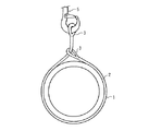
Further, since the belt sling cannot be sufficiently wrapped around the load in the basket hanging, for example, as shown in FIG. 12, the belt sling 1 is wrapped around the
[0004]
[Patent Document 1]
JP, 11-43280, A [Problems to be solved by the invention]
However, when the luggage is lifted by the above-described chalk suspension, a substantially triangular gap is generated between the part where one eye 3 is inserted into the other eye 3 and the
[0005]
Also, for example, as shown in FIG. 13, the belt sling 1 may be wrapped around the
[0006]
In particular, when the
[0007]
The present invention has been made to solve such a problem, and an object of the present invention is to provide a belt sling capable of securing a stable lifting operation.
[0008]
[Means for Solving the Problems]
In order to achieve the above object, the invention according to claim 1 is a fiber belt sling, wherein the plurality of connection links are connected in a chain and at least one of the connection links is connected. And a branch link.
[0009]
According to such a configuration, for example, when a belt sling is wrapped around a load, tightened, and then lifted by a hanging tool, if the hanging tool is hooked on the branch link and lifted, the branch link is lifted by the lifting tool. Since the connecting link is not directly lifted by the lifting device, a substantially triangular gap can be prevented from being generated between the load and the belt sling. Therefore, a stable lifting operation can be ensured.
[0010]
According to a second aspect of the present invention, in the first aspect of the present invention, when the branch link is pulled in a state where the belt sling is hung around a load, the connection link to which the branch link is connected is connected. The branch link is connected to the connection link such that the connection links on both sides move in a direction approaching each other and the load is fastened.
[0011]
According to such a configuration, for example, the belt sling is wrapped around the luggage, and after tightening, if the lifting device is hooked on the branch link and lifted, the branch link is pulled in the lifting direction of the lifting device, whereby The connecting links on both sides of the connecting link to which the branch link is connected move in the direction approaching each other, and the load is tightened. Therefore, in the belt sling, if the branch link is lifted by the lifting device, the load is lifted while being wound up, so that a more stable lifting operation can be secured.
[0012]
According to a third aspect of the present invention, in the first or second aspect, the branch link is connected to each of the connection links.
[0013]
According to such a configuration, since the branch links are connected to each of the connection links, any branch link can be lifted from any angle according to the work environment. Therefore, the lifting operation can be facilitated and the efficiency can be improved.
[0014]
BEST MODE FOR CARRYING OUT THE INVENTION
FIG. 1 is a side view showing an embodiment of the belt sling of the present invention, and FIGS. 2 and 3 are side views for explaining a use mode of the belt sling.
[0015]
In FIG. 1, the
[0016]
Each connecting
[0017]
Each of the connecting
[0018]
Like the
[0019]
Then, in such a
[0020]
Also, as shown in FIG. 3, for example, if the
[0021]
When a tubular
[0022]
The loading of the
[0023]
In order to lift the
[0024]
When the lifting is performed in this manner, as shown in FIG. 5, the branch link 13 (the
[0025]
Further, since the branch link 13 (the
[0026]
Then, in order to actually lift the
[0027]
Further, in the
[0028]
In particular, when this
[0029]
Note that FIG. 8 shows a single hanging mode in which one
[0030]
In the above description, the lifting of the
[0031]
For example, as shown in FIG. 10, instead of the
[0032]
In addition, the
[0033]
That is, the irregularly shaped
[0034]
In order to lift such a
[0035]
By lifting in this manner, a favorable lifting operation can be ensured even for the irregularly shaped
[0036]
In the above description, the
[0037]
In addition, the branch links do not necessarily need to be connected to the connection links (that is, the number of the branch links and the connection links need not be the same), and may be appropriately determined according to the purpose and use. .
[0038]
In addition, the shape of the connecting link and the branch link is not limited to an oval ring, and may be an appropriate shape such as a ring.
[0039]
【The invention's effect】
As described above, according to the first aspect of the invention, a stable lifting operation can be ensured.
[0040]
According to the second aspect of the present invention, if the branch link is lifted by the lifting device, the load can be lifted while being tightened, so that a more stable lifting operation can be secured.
[0041]
According to the third aspect of the invention, the lifting operation can be facilitated and the efficiency can be improved.
[Brief description of the drawings]
FIG. 1 is a side view showing an embodiment of a belt sling of the present invention.
FIG. 2 is a side view for explaining a use mode (a mode of gripping connecting links at both ends) of the belt sling shown in FIG. 1;
FIG. 3 is a side view for explaining a use mode of the belt sling shown in FIG. 1 (a mode of gripping branch links at both ends).
FIG. 4 is a side view illustrating a use mode (a mode of lifting a tubular member) of the belt sling illustrated in FIG.
FIG. 5 is an enlarged side view of a main part of a usage mode of the belt sling shown in FIG.
FIG. 6 is a perspective view illustrating a use mode (a mode in which the tubular member is lifted (laterally suspended)) of the belt sling illustrated in FIG.
FIG. 7 is a side view illustrating a use mode (a mode in which the tubular member is lifted in an arbitrary direction) of the belt sling illustrated in FIG.
8 is a perspective view illustrating a use mode (a mode in which a tubular member is lifted (vertically (single)) in use of the belt sling illustrated in FIG.
FIG. 9 is a perspective view illustrating a use mode (a mode in which a tubular member is lifted (vertical (two) is suspended)) of the belt sling illustrated in FIG.
FIG. 10 is a side view illustrating a use mode (a mode in which a square column is lifted) of the belt sling illustrated in FIG. 1;
FIG. 11 is a front view illustrating a use mode (a mode in which a deformed member is lifted) of the belt sling illustrated in FIG. 1;
FIG. 12 is a side view illustrating a usage mode of a conventional belt sling (a mode in which a load is choked).
FIG. 13 is a side view illustrating a usage state of a conventional belt sling (an aspect in which a load is fastened using a chain lever hoist).
FIG. 14 is an enlarged side view of a main part of FIG.
[Explanation of symbols]
DESCRIPTION OF SYMBOLS 1
Claims (3)
連鎖状に連結されている複数の連結リンクと、
前記連結リンクの少なくとも1つに連結されている分岐リンクとを備えていることを特徴とする、ベルトスリング。A belt sling made of fiber,
A plurality of connection links connected in a chain,
And a branch link connected to at least one of the connection links.
Priority Applications (1)
| Application Number | Priority Date | Filing Date | Title |
|---|---|---|---|
| JP2002269898A JP3782988B2 (en) | 2002-09-17 | 2002-09-17 | Belt sling |
Applications Claiming Priority (1)
| Application Number | Priority Date | Filing Date | Title |
|---|---|---|---|
| JP2002269898A JP3782988B2 (en) | 2002-09-17 | 2002-09-17 | Belt sling |
Publications (2)
| Publication Number | Publication Date |
|---|---|
| JP2004106979A true JP2004106979A (en) | 2004-04-08 |
| JP3782988B2 JP3782988B2 (en) | 2006-06-07 |
Family
ID=32267686
Family Applications (1)
| Application Number | Title | Priority Date | Filing Date |
|---|---|---|---|
| JP2002269898A Expired - Fee Related JP3782988B2 (en) | 2002-09-17 | 2002-09-17 | Belt sling |
Country Status (1)
| Country | Link |
|---|---|
| JP (1) | JP3782988B2 (en) |
Cited By (2)
| Publication number | Priority date | Publication date | Assignee | Title |
|---|---|---|---|---|
| JP2009001360A (en) * | 2007-06-20 | 2009-01-08 | Chugoku Electric Power Co Inc:The | Sling rope |
| JP2019189400A (en) * | 2018-04-25 | 2019-10-31 | 株式会社Ihi | Lifting tool system |
-
2002
- 2002-09-17 JP JP2002269898A patent/JP3782988B2/en not_active Expired - Fee Related
Cited By (3)
| Publication number | Priority date | Publication date | Assignee | Title |
|---|---|---|---|---|
| JP2009001360A (en) * | 2007-06-20 | 2009-01-08 | Chugoku Electric Power Co Inc:The | Sling rope |
| JP2019189400A (en) * | 2018-04-25 | 2019-10-31 | 株式会社Ihi | Lifting tool system |
| JP7214977B2 (en) | 2018-04-25 | 2023-01-31 | 株式会社Ihi | sling system |
Also Published As
| Publication number | Publication date |
|---|---|
| JP3782988B2 (en) | 2006-06-07 |
Similar Documents
| Publication | Publication Date | Title |
|---|---|---|
| CA2783260C (en) | Adjustable spreader bar system | |
| US6019403A (en) | Wire rope spreader | |
| JPH11246164A (en) | Suspension accessory for tube bundle | |
| US11002026B1 (en) | Adjustable suspension assembly | |
| JPS6050711B2 (en) | Self-locking sling method and sling | |
| JP3782988B2 (en) | Belt sling | |
| JP2003306291A (en) | Heavy lifting equipment such as steel plate | |
| CN201074158Y (en) | Sling assembly for lifting vertical steel coils | |
| WO2000017085A1 (en) | Lifting sling system having multiple strap components | |
| JP2008230641A (en) | Belt | |
| CN213475153U (en) | A fuel tank handling auxiliary mechanism | |
| CN116002498A (en) | Sling suitable for large-scale distortion component | |
| JP2514314Y2 (en) | Suspension equipment for mountain retaining materials | |
| CN210340060U (en) | Equidistant lifting hook carrying pole for traveling crane | |
| JP3125406U (en) | Transportation hanger | |
| US20250282581A1 (en) | Pipe sling | |
| CN213445765U (en) | Gripping device for pipeline transportation | |
| JP2001080887A (en) | Low head type electric hoist | |
| JP2006160490A (en) | Hanging device using belt sling | |
| JP5690084B2 (en) | Attachment for forklift and load handling method using the same | |
| CN219009676U (en) | Sling suitable for large-scale distortion component | |
| JP3241837U (en) | cargo handling slings | |
| CN222204532U (en) | Clamping structure and lifting device of foil reel | |
| JP7466859B2 (en) | Fittings and slings | |
| JP2003341974A (en) | Hoisting device, hoisting member and hoisting metal fitting |
Legal Events
| Date | Code | Title | Description |
|---|---|---|---|
| A621 | Written request for application examination |
Free format text: JAPANESE INTERMEDIATE CODE: A621 Effective date: 20040623 |
|
| A131 | Notification of reasons for refusal |
Free format text: JAPANESE INTERMEDIATE CODE: A131 Effective date: 20051004 |
|
| A521 | Written amendment |
Free format text: JAPANESE INTERMEDIATE CODE: A523 Effective date: 20051130 |
|
| TRDD | Decision of grant or rejection written | ||
| A01 | Written decision to grant a patent or to grant a registration (utility model) |
Free format text: JAPANESE INTERMEDIATE CODE: A01 Effective date: 20060221 |
|
| A61 | First payment of annual fees (during grant procedure) |
Free format text: JAPANESE INTERMEDIATE CODE: A61 Effective date: 20060313 |
|
| R150 | Certificate of patent (=grant) or registration of utility model |
Free format text: JAPANESE INTERMEDIATE CODE: R150 |
|
| LAPS | Cancellation because of no payment of annual fees |