JP2004129985A - Snap fastener with tape - Google Patents
Snap fastener with tape Download PDFInfo
- Publication number
- JP2004129985A JP2004129985A JP2002300076A JP2002300076A JP2004129985A JP 2004129985 A JP2004129985 A JP 2004129985A JP 2002300076 A JP2002300076 A JP 2002300076A JP 2002300076 A JP2002300076 A JP 2002300076A JP 2004129985 A JP2004129985 A JP 2004129985A
- Authority
- JP
- Japan
- Prior art keywords
- engagement
- tape
- base
- engaging
- projection
- Prior art date
- Legal status (The legal status is an assumption and is not a legal conclusion. Google has not performed a legal analysis and makes no representation as to the accuracy of the status listed.)
- Pending
Links
Images



Landscapes
- Slide Fasteners, Snap Fasteners, And Hook Fasteners (AREA)
Abstract
【目的】雌雄部材が同体のテープ付きスナップファスナを提供する。
【構成】雌雄同体の合成樹脂製係合部材(2)の複数個を所定間隔で生地テープに成形固定したテープ(3)からなる。前記係合部材(2)の係合側表面は、ベース(4)と、係合突起(6)と、係合突起受容部(7)を有する。前記係合突起(6)と前記係合突起受容部(7)のそれぞれが小突起(6g,4b)とくぼみ(6h,4c)を有する。前記係合部材(2)同士が係合したとき、前記小突起(6g,4b)とくぼみ(6h,4c)がはまり合う。
【選択図】 図2[Object] To provide a snap fastener with a tape in which male and female members are the same.
The present invention comprises a tape (3) in which a plurality of hermaphroditic synthetic resin engaging members (2) are formed and fixed on a cloth tape at predetermined intervals. The engagement side surface of the engagement member (2) has a base (4), an engagement protrusion (6), and an engagement protrusion receiving portion (7). Each of the engagement protrusion (6) and the engagement protrusion receiving portion (7) has a small protrusion (6g, 4b) and a recess (6h, 4c). When the engaging members (2) are engaged with each other, the small projections (6g, 4b) and the depressions (6h, 4c) are fitted.
[Selection] Fig. 2
Description
【0001】
【発明の属する技術分野】
本発明はテープ付きスナップファスナに関する。
【0002】
【従来の技術】
本出願人は、以下のようなテープ付きスナップファスナを開発し、出願してきた。
(1)特開平10−33210号
(2)特開平10−33211号
(3)特開2000−270906
(4)特開2001−8711
(5)特開2001−78807
(6)特開2001−64515
(7)特開2001−149117
(8)特開2002−318
(9)特開2002−125719
(10)特開2002−125720
(11)特開2002−238620
【0003】
上記従来技術(1)−(10)のスナップファスナは、雄部材を有する雄側テープと雌部材を有する雌側テープを組み合わせている。必ず両部材を必要とするので、雌雄部材それぞれに金型を製作して、それに基づき二種類のテープを製造し、それらを間違えないように分類、保管、箱詰め、配送、使用しなければならなかった。
【0004】
この問題を解決するために、上記(11)の先願において、雌雄2種類のテープを必要とせず、雌部材のみで用が足りるようなスナップファスナを本出願人は提案した。
【0005】
【発明が解決しようとする課題】
上記特開2002−238620は確かに係合部材が1種類のテープではあるが、別に両者をつなぎ止めるためのつなぎ部材を必要としている。このつなぎ部材は簡単な部品であるが、それでも金型製作、分類、保管、箱詰め、配送、使用等の面で特別な配慮が必要である。
【0006】
本発明は、雌雄係合部材が同体のテープであるため1種類のテープであり、しかも連結するためにつなぎ部材も必要としないテープ付きスナップファスナを提供することを目的とする。
【0007】
【課題を解決するための手段】
本発明のテープ付きファスナは、雌雄同体の合成樹脂製係合部材を所定間隔で生地テープに成形固定したテープからなり、前記係合部材の係合側表面は、ベースと、少なくとも1個の係合突起と、少なくとも1個の係合突起受容部を有し、さらに前記係合突起と前記係合突起受容部のそれぞれが小突起とくぼみを有し、前記係合部材同士が係合したとき、前記小突起とくぼみがはまり合うことを特徴とする。
【0008】
【発明の実施の態様】
前記係合突起と前記係合突起受容部はベースに囲まれた中央部に設けるのが設計上好ましい。前記係合突起受容部底面において生地テープ露出部を設けるのが成形上強度を保つために好ましい。
【0009】
前記係合突起の小突起とくぼみは、例えば外方側の突起側壁に形成されたものとすることができる。
【0010】
前記係合突起受容部の小突起とくぼみは、例えば内方側のベース側壁に形成されたものとすることができる。
【0011】
前記ベースの小突起に隣接して傾斜部を設けるのが好ましい。
【0012】
【実施例】
以下、添付の図面に基づき、本発明の実施例を説明する。
【0013】
<第1実施例>
図1は、本発明第1実施例に係る、雌雄部材が同体のテープ付きスナップファスナ1の平面図である。所定間隔をあけて雌雄同体の複数の係合部材2を設けたテープ3同士を係合させる。使用時には、テープ3は2本一対で用いるが、本発明では雌雄同体であるため、図1では1本しか描いていない。
【0014】
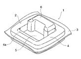
図2は雌雄同体の係合部材2の拡大斜視図である。図3は同部材の平面図(a)、側面図(b)、断面図(c)である。
【0015】
この係合部材の係合面となる表面側は、四角い枠からなるベース4と、枠内の中央部5からなり、中央部5はさらに、係合突起部6と係合突起受容部7からなる。係合突起受容部7では、金型の形状に応じて生地テープ3が他の部分の生地よりも低く押しつけられている(図3(c)参照)と共に、生地テープが露出している。ただし、係合突起受容部7において生地テープ3が他の部分の生地よりも低く設定されているのは、本発明にとって必須ではない。
【0016】
ベース4のうち、係合突起受容部7側の側壁には、図3(c)に示すように、傾斜部4aと、小突起部4bと、くぼみ部4cがそれぞれ形成されている。
【0017】
係合突起部6は、図3(a)に示すように、中央部の約半分を占めている。係合突起部6は、縦方向の主要部分6cと、その上下にあって横方向に伸びる延長部分6a,6bからなり、上から見ると「コ」の字型の頂部6dを有する。図3(c)に示すように、係合突起部6のうち、係合突起受容部7側の側壁には、傾斜部6eと垂直部6fが隣り合わせに設けられている。係合突起部6のうち、主要部分6cに隣接したベース4側の突起側壁には、小突起部6gと、くぼみ部6hが設けられている。係合突起部6のうち、上下延長部分6a,6bに隣接したベース4側の突起側壁には、傾斜部6jと垂直部6kが設けられている(図3(b)参照)。
【0018】
この係合部材の非係合面である裏側は、四角い枠からなる裏側ベース8と、枠内の中央部9からなり、中央部9は生地テープが露出している。
【0019】
この係合部材2を成形するには、ファスナ成形用空間を形成した上下金型(図示せず)間に、溶融樹脂が成形圧力によって通過浸透する粗さの生地テープ3を配設し、中央部5,9の生地テープ3を前記上下金型で挟み込み固定し、その後、合成樹脂を前記成形空間内に射出する。図3(c)の符号の小さなくぼみ10が金型の射出口に相当する。この射出口設定のために裏側ベース8の枠幅が表側ベース4の枠幅よりもやや幅広となる。
【0020】
このようにして、生地テープ両面に形成される係合部材2の表面側と裏面側とが生地テープ3を透過する合成樹脂によって一体化される。
【0021】
テープ生地3としては、溶融されることなく溶融樹脂が透過する生地であることが必要で、織物でも編物でもよく、例えば木綿生地、混紡生地等を採用することができる。合成樹脂としては、熱可塑性樹脂、例えばポリアセタール溶融樹脂を使用することができる。
【0022】
この雌雄同体係合部同士を組み合わせた状態を図4に示す。図4における上側係合部の係合突起6の突起部6gと下側係合部のベース4のくぼみ部4cが係合していること、上側係合部のベース4のくぼみ部4cと下側係合部の係合突起6の小突起部6gが係合していることが分かる。これにより、2つの係合部同士は確実に係合することができる。
【0023】
この係合を解除するには、指で各部材にひねりを加えたり、生地をつかんで強く引き剥がしたりすればよい。
【0024】
<第2実施例>
第2実施例でも第1実施例と同様に、所定間隔をあけて雌雄同体の複数の係合部材20を設けたテープ21同士を係合させる。図5は第2実施例に係る雌雄同体の係合部材20の拡大斜視図である。図6(a)は同部材の平面図、(b)はb−b断面図、(c)はc−c断面図、(d)は背面図である。第7図は雌雄同体の係合部材の係合状態を示す断面図である。
【0025】
この係合部材20の係合面となる表面側は、図6(a)に示すように、リング状のベース23,24とベース内の中央部22からなる。ベースは2個の高ベース23と2個の低ベース24からなり、中央部22は2個の係合突起25と2個の係合突起受容部26からなる。
【0026】
図6(a)に示すように、高ベース23と低ベース24は、リング状の枠を4等分して、交互に2個ずつ設定されている。生地上の高さは、高ベース23は低ベース24の約2倍である。図6(c)に示すように、高ベース23のうち、係合突起受容部26側のベース側壁には、傾斜部23aと、小突起部23bと、くぼみ部23cがそれぞれ形成されている。
【0027】
中央部22では、金型の形状に応じて生地テープ21が他の部分の生地よりも低く押しつけられている(図6(b)(c)参照)と共に、生地テープ21が露出している。ただし、中央部22において生地テープ21が他の部分の生地よりも低く設定されているのは、本発明にとって必須ではない。
【0028】
2個の係合突起25は平面から見ると扇形であり、2個の低ベース24の内側にそれぞれ位置している。係合突起25の高さは、図7に示すように、高ベース23と低ベース24の高さを合わせた高さである。
【0029】
2個の係合突起受容部26は、前記2個の係合突起25に円周方向に隣接したスペースである。係合突起受容部26及び中央部22の中心では完全に生地テープ21が露出している。
【0030】
この係合部材の非係合面である裏側は、リング状の枠からなるベース27と、枠内の中央部28からなり、中央部は生地テープが露出している。
【0031】
第2実施例の雌雄同体係合部の製造方法は第1実施例に準ずる。図6(d)の符号の小さなくぼみ29が金型の射出口に相当する。
【0032】
この雌雄同体係合部同士を組み合わせた状態を図7に示す。図7における上側係合部の係合突起25の突起部25aと下側係合部の高ベース23のくぼみ23cが係合していること、上側係合部の高ベース23のくぼみ部23cと下側係合部の係合突起25の小突起部25aが係合していることが分かる。これにより、2つの係合部同士は確実に係合することができる。
【0033】
この係合を解除するには、指で各部材にひねりを加えたり、生地をつかんで強く引き剥がしたりすればよい。
【0034】
第2実施例では、高ベース23と低ベース24をそれぞれ2個設けているが、1個ずつでもよい。その場合は、それぞれがベースの半周を担当することになる。
【0035】
【発明の効果】
本発明によれば、雌雄係合部材が同体であるためテープは1種類でよい。また、両者をつなぎ止めるためのつなぎ部材も必要としない。完全に1種類の部材で用が足りるので、製造、分類、保管、箱詰め、配送、使用などで省力化やコスト削減を図ることができる。
【図面の簡単な説明】
【図1】本発明第1実施例に係る、雌雄部材が同体のテープの平面図である。
【図2】同部材の斜視図である。
【図3】(a)は同部材の平面図、(b)は側面図、(c)は断面図である。
【図4】同部材の係合状態を示す断面図である。
【図5】本発明第2実施例に係る雌雄同体の係合部材の拡大斜視図である。
【図6】(a)は同部材の平面図、(b)はA−A断面図、(c)はB−B断面図、(d)は背面図である。
【図7】同部材の係合状態を示す断面図である。
【符号の説明】
<第1実施例>
1 スナップファスナ
2 係合部材
3 生地テープ
4 ベース
4a 傾斜部
4b 小突起部
4c くぼみ部
5 中央部
6 係合突起
6g 小突起部
6h くぼみ部
7 係合突起受容部
<第2実施例>
20 係合部材
21 生地テープ
22 中央部
23 高ベース
23b 小突起部
23c くぼみ部
24 低ベース
25 係合突起
25a 小突起部
25b くぼみ部
26 係合突起受容部
27 裏側ベース[0001]
TECHNICAL FIELD OF THE INVENTION
The present invention relates to a snap fastener with a tape.
[0002]
[Prior art]
The applicant has developed and applied for the following snap fastener with tape.
(1) JP-A-10-33210 (2) JP-A-10-33211 (3) JP-A-2000-270906
(4) JP-A-2001-8711
(5) JP-A-2001-78807
(6) JP-A-2001-64515
(7) JP-A-2001-149117
(8) JP-A-2002-318
(9) JP-A-2002-125719
(10) JP-A-2002-125720
(11) JP-A-2002-238620
[0003]
The snap fasteners of the prior arts (1) to (10) combine a male tape having a male member and a female tape having a female member. Since both parts are always required, molds must be manufactured for each male and female member, and two types of tapes must be manufactured based on them, and they must be sorted, stored, boxed, delivered, and used without mistake. Was.
[0004]
In order to solve this problem, the applicant of the present application has proposed a snap fastener which does not require two types of male and female tapes and requires only a female member.
[0005]
[Problems to be solved by the invention]
Although the above-mentioned Japanese Patent Application Laid-Open No. 2002-238620 certainly uses one type of tape, it requires a separate connecting member for connecting the two. Although this connecting member is a simple part, it still requires special considerations in terms of mold making, classification, storage, packing, delivery, use, and the like.
[0006]
SUMMARY OF THE INVENTION It is an object of the present invention to provide a snap fastener with a tape which is a kind of tape because the male and female engaging members are the same tape, and does not require a connecting member for connection.
[0007]
[Means for Solving the Problems]
A fastener with a tape according to the present invention comprises a tape in which hermaphroditic synthetic resin engaging members are formed and fixed on a cloth tape at predetermined intervals, and the engaging side surface of the engaging member is in contact with a base and at least one engaging member. A projection, having at least one engagement projection receiving portion, each of the engagement projection and the engagement projection receiving portion having a small projection and a recess, when the engagement members are engaged with each other, The small projections and the depressions are fitted.
[0008]
DESCRIPTION OF THE PREFERRED EMBODIMENTS
It is preferable in terms of design that the engaging protrusion and the engaging protrusion receiving portion are provided at a central portion surrounded by a base. It is preferable to provide a material tape exposed portion on the bottom surface of the engagement protrusion receiving portion in order to maintain strength in molding.
[0009]
The small projections and depressions of the engagement projections may be formed on, for example, the outer side wall of the projection.
[0010]
The small projections and depressions of the engagement projection receiving portion may be formed, for example, on the inner side wall of the base.
[0011]
Preferably, an inclined portion is provided adjacent to the small projection of the base.
[0012]
【Example】
Hereinafter, embodiments of the present invention will be described with reference to the accompanying drawings.
[0013]
<First embodiment>
FIG. 1 is a plan view of a snap fastener 1 with a tape in which male and female members are the same according to a first embodiment of the present invention. At predetermined intervals, the
[0014]
FIG. 2 is an enlarged perspective view of the
[0015]
The front side, which is the engaging surface of the engaging member, includes a
[0016]
As shown in FIG. 3 (c), on the side wall of the
[0017]
As shown in FIG. 3A, the
[0018]
The back side, which is the non-engagement surface of the engaging member, comprises a
[0019]
In order to form the engaging
[0020]
In this way, the front side and the back side of the engaging
[0021]
The
[0022]
FIG. 4 shows a state in which the hermaphroditic engagement portions are combined. The engagement between the
[0023]
To release the engagement, a twist may be applied to each member with a finger, or the cloth may be grasped and strongly peeled off.
[0024]
<Second embodiment>
In the second embodiment, as in the first embodiment, the
[0025]
As shown in FIG. 6 (a), the front side of the
[0026]
As shown in FIG. 6A, the
[0027]
In the
[0028]
The two
[0029]
The two engagement
[0030]
The back side, which is the non-engagement surface of this engagement member, comprises a base 27 formed of a ring-shaped frame and a
[0031]
The method of manufacturing the hermaphroditic engagement portion of the second embodiment is similar to that of the first embodiment. The
[0032]
FIG. 7 shows a state in which the hermaphroditic engagement portions are combined. 7 that the
[0033]
To release the engagement, a twist may be applied to each member with a finger, or the cloth may be grasped and strongly peeled off.
[0034]
In the second embodiment, two
[0035]
【The invention's effect】
According to the present invention, since the male and female engaging members are the same, only one type of tape is required. Also, a connecting member for connecting the two is not required. Since only one kind of member is sufficient, labor saving and cost reduction can be achieved in manufacturing, sorting, storage, packing, delivery, use, and the like.
[Brief description of the drawings]
FIG. 1 is a plan view of a tape in which male and female members are the same according to a first embodiment of the present invention.
FIG. 2 is a perspective view of the same member.
3A is a plan view of the same member, FIG. 3B is a side view, and FIG. 3C is a cross-sectional view.
FIG. 4 is a sectional view showing an engaged state of the member.
FIG. 5 is an enlarged perspective view of a hermaphroditic engagement member according to a second embodiment of the present invention.
6A is a plan view of the same member, FIG. 6B is a cross-sectional view taken along line AA, FIG. 6C is a cross-sectional view taken along line BB, and FIG.
FIG. 7 is a sectional view showing an engaged state of the same member.
[Explanation of symbols]
<First embodiment>
DESCRIPTION OF SYMBOLS 1
Claims (6)
前記係合部材(2;20)の係合側表面は、ベース(4;23,24)と、少なくとも1個の係合突起(6;25)と、少なくとも1個の係合突起受容部(7;26)を有し、
さらに前記係合突起(6;25)と前記係合突起受容部(7;26)のそれぞれが小突起(6g,4b;25a,23a)とくぼみ部(6h,4c;25b,23b)を有し、前記係合部材(2,20)同士が係合したとき、前記小突起(6g,4b;25a,23a)とくぼみ(6h,4c;25b,23b)がはまり合うことを特徴とするテープ付きファスナ。A tape (3; 21) in which hermaphroditic synthetic resin engaging members (2; 20) are formed and fixed to a cloth tape at predetermined intervals;
The engaging surface of the engaging member (2; 20) includes a base (4; 23, 24), at least one engaging protrusion (6; 25), and at least one engaging protrusion receiving portion ( 7; 26),
Further, each of the engaging projection (6; 25) and the engaging projection receiving section (7; 26) has a small projection (6g, 4b; 25a, 23a) and a concave section (6h, 4c; 25b, 23b). When the engaging members (2, 20) are engaged with each other, the small projections (6g, 4b; 25a, 23a) and the recesses (6h, 4c; 25b, 23b) fit together. With fasteners.
Priority Applications (1)
| Application Number | Priority Date | Filing Date | Title |
|---|---|---|---|
| JP2002300076A JP2004129985A (en) | 2002-10-15 | 2002-10-15 | Snap fastener with tape |
Applications Claiming Priority (1)
| Application Number | Priority Date | Filing Date | Title |
|---|---|---|---|
| JP2002300076A JP2004129985A (en) | 2002-10-15 | 2002-10-15 | Snap fastener with tape |
Publications (1)
| Publication Number | Publication Date |
|---|---|
| JP2004129985A true JP2004129985A (en) | 2004-04-30 |
Family
ID=32289030
Family Applications (1)
| Application Number | Title | Priority Date | Filing Date |
|---|---|---|---|
| JP2002300076A Pending JP2004129985A (en) | 2002-10-15 | 2002-10-15 | Snap fastener with tape |
Country Status (1)
| Country | Link |
|---|---|
| JP (1) | JP2004129985A (en) |
Cited By (1)
| Publication number | Priority date | Publication date | Assignee | Title |
|---|---|---|---|---|
| WO2010095266A1 (en) * | 2009-02-23 | 2010-08-26 | Ykk株式会社 | Snap button |
-
2002
- 2002-10-15 JP JP2002300076A patent/JP2004129985A/en active Pending
Cited By (2)
| Publication number | Priority date | Publication date | Assignee | Title |
|---|---|---|---|---|
| WO2010095266A1 (en) * | 2009-02-23 | 2010-08-26 | Ykk株式会社 | Snap button |
| US8484813B2 (en) | 2009-02-23 | 2013-07-16 | Ykk Corporation | Snap button |
Similar Documents
| Publication | Publication Date | Title |
|---|---|---|
| US6401308B1 (en) | Tape-mounted snap fastener having engagement and disengagement directionality | |
| JP2536899Y2 (en) | buckle | |
| CN1985695B (en) | waterproof zipper | |
| KR950001606Y1 (en) | Molded Surface Fasteners | |
| EP1048234A1 (en) | A snap fastener having a detachment directionality | |
| US6976291B2 (en) | Tape-mounted fastener and methods for manufacturing and using the same | |
| US7340806B2 (en) | Opener for slide fastener | |
| US6851161B2 (en) | Sealing closures | |
| CN101023823A (en) | waterproof zipper | |
| US20120279022A1 (en) | Cord Fastener | |
| JP2004129985A (en) | Snap fastener with tape | |
| EP1272398B1 (en) | Sealing closures | |
| JP3952433B2 (en) | Clothes hook | |
| KR850001442Y1 (en) | Slide Fastener Stringer | |
| EP0292892B1 (en) | Pair of snappingly engageable members | |
| KR20020001524A (en) | A fasteners | |
| CN1615766A (en) | Buckle with mesh cover | |
| CN210203589U (en) | Fastener element, fastener tape, and slide fastener | |
| CN218390039U (en) | Backpack zipper and upper stop device thereof | |
| JP3663138B2 (en) | Snap fastener with tape | |
| JPH09289914A (en) | Zipper bag and manufacturing method thereof | |
| JP4052949B2 (en) | Snap fastener with peel direction | |
| CN102878160B (en) | Mechanical surface bonding fastener | |
| JP2003289909A (en) | Molded surface fastener with tape | |
| JP2521811Y2 (en) | Container and cap mounting structure |
Legal Events
| Date | Code | Title | Description |
|---|---|---|---|
| A621 | Written request for application examination |
Effective date: 20050225 Free format text: JAPANESE INTERMEDIATE CODE: A621 |
|
| A977 | Report on retrieval |
Free format text: JAPANESE INTERMEDIATE CODE: A971007 Effective date: 20060804 |
|
| A131 | Notification of reasons for refusal |
Effective date: 20060815 Free format text: JAPANESE INTERMEDIATE CODE: A131 |
|
| A02 | Decision of refusal |
Effective date: 20070116 Free format text: JAPANESE INTERMEDIATE CODE: A02 |