【0001】
【発明の属する技術分野】
この発明は、照明器具等の包装に使用する固定パッド付き包装箱に関する。
【0002】
【従来の技術】
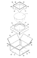
例えば、円形の照明器具を包装する際には、図6に示すように、対向する2組の側板51,52の上下縁から内フラップ53及び外フラップ54をそれぞれ延出した段ボール製の包装箱50が使用される。
【0003】
この包装箱50には、底面を閉止した状態で、下パッド55が挿入される。下パッド55は、円形の切抜穴57を有する支持板56の各辺から脚板58を延出して下方へ折り曲げたものであり、その切抜穴57に照明器具Lを嵌め込むようにセットすると、下パッド55で照明器具Lの移動が阻止される。
【0004】
そして、照明器具Lの上には、上パッド59が載置される。この上パッド59は、枡形に連設した載置板60の下部に弧状縁61を形成したものであり、図7に示すように、照明器具Lの上面に弧状縁61を沿わせ、包装箱50の天面側の内フラップ53及び外フラップ54を折り重ねて封緘すると、上パッド59で天面側に緩衝空間が確保される。
【0005】
【発明が解決しようとする課題】
しかしながら、上記のように、包装箱50の他に、別途パッド55,59を挿入して収納物を固定する包装形態では、多量の材料を必要とするほか、パッド55,59の組立や挿入等に手間がかかるという問題もある。
【0006】
そこで、この発明は、収納物を少量の材料で簡単に固定して包装できる包装箱を提供しようとするものである。
【0007】
【課題を解決するための手段】
上記課題を解決するため、この発明は、対向する2組の側板からそれぞれ内フラップ及び外フラップを延出した包装箱において、底面側の内フラップを先端中央部から基端両側方へ切り込んで形成した巻込片を巻き込み、その先端部を巻込片の外側に形成した差込穴に差し込んで、巻込片の巻込状態を保持し、4個の巻込片を収納物の外周に沿わせて、収納物の移動を阻止するようにしたのである。
【0008】
【発明の実施の形態】
この実施形態に係る包装箱の段ボール製ブランクでは、図1に示すように、側板1,2が2枚ずつ交互に連設され、その下縁に内フラップ3及び外フラップ4が、上縁に内フラップ5及び外フラップ6がそれぞれ連設されている。また、一方の側板2の外側縁には継代片7が連設されている。
【0009】
下方の内フラップ3には、先端中央部から基端両側方へ切り込んで、基端及び中間部に幅方向の折目を有する斜向きの巻込片8が形成され、巻込片8の基端折目より外側にコ字状の差込穴9が形成されている。巻込片8の先端部では、段ボールが押し潰されている。
【0010】
また、上方の内フラップ5には、多数の縦切目及び横折目を入れて、交互にずれた頂部10が形成され、その先端側に巻込部11が形成されている。
【0011】
上記のようなブランクを組み立てて円形の照明器具を包装する際には、図2に示すように、各一対の側板1,2を継代片7を介して接合し、下方の内フラップ3及び外フラップ4を重ね合わせて固着し、底面を閉止する。
【0012】
そして、各巻込片8を折目沿いに上方外側へ巻き込むように折り曲げ、その先端部を差込穴9に差し込んで、巻込片8を巻き込んだ状態に保持する。
【0013】
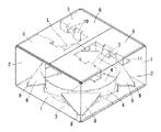
この状態で、円形の照明器具Lを4個の巻込片8の内側に挿入すると、図2及び図5に示すように、巻込片8が照明器具Lの外周に沿うので、箱内での照明器具Lの移動が阻止される。
【0014】
次に、上方の内フラップ5を巻き込んで、頂部10を交互に傾斜させ、図3及び図4に示すように、巻込部11が照明器具Lの上面に沿うようにし、外フラップ6を重ねて封緘すると、照明器具Lの上側に緩衝空間が確保される。
【0015】
このような包装箱では、別途パッドを使用することなく、円形の照明器具Lを固定できるので、材料の使用量が抑制され、また、従来の包装箱と同一輪郭のブランクから組み立てるので、従来の製造ラインをそのまま使用できる。
【0016】
また、底組み時には、巻込片8を巻き込んで、その先端部を差込穴9に差し込むだけであり、封緘時には、上方の内フラップ5を巻き込むだけなので、作業性がよく、照明器具Lの包装作業を迅速に行うことができる。
【0017】
【発明の効果】
以上のように、この発明に係る包装箱では、側板から延出した内フラップを巻き込んで、収納物を固定することとしたので、別部材のパッドが不要となり、材料の使用量が抑制されるほか、包装時にパッドの組立や挿入を行う必要がなく、包装作業性も向上する。
【図面の簡単な説明】
【図1】この発明に係る包装箱のブランクを示す図
【図2】同上の包装過程を示す斜視図
【図3】同上の包装状態を示す斜視図
【図4】同上の縦断正面図
【図5】同上の横断平面図
【図6】従来の包装形態を示す分解斜視図
【図7】同上の包装状態を示す斜視図
【符号の説明】
1,2 側板
3,5 内フラップ
4,5 外フラップ
8 巻込片
9 差込穴[0001]
TECHNICAL FIELD OF THE INVENTION
The present invention relates to a packaging box with fixed pads used for packaging lighting equipment and the like.
[0002]
[Prior art]
For example, when packaging a circular lighting fixture, as shown in FIG. 6, a cardboard packaging box in which an inner flap 53 and an outer flap 54 are respectively extended from upper and lower edges of two sets of opposed side plates 51 and 52. 50 are used.
[0003]
The lower pad 55 is inserted into the packaging box 50 with the bottom face closed. The lower pad 55 is formed by extending a leg plate 58 from each side of the support plate 56 having a circular cutout hole 57 and bending the leg plate 58 downward. When the lighting device L is set so as to fit into the cutout hole 57, the lower pad 55 The movement of the lighting fixture L is prevented by the pad 55.
[0004]
Then, the upper pad 59 is placed on the lighting fixture L. The upper pad 59 is formed by forming an arc-shaped edge 61 at a lower portion of a mounting plate 60 continuously connected in a square shape, and as shown in FIG. When the inner flap 53 and the outer flap 54 on the top side of 50 are folded and sealed, the upper pad 59 secures a buffer space on the top side.
[0005]
[Problems to be solved by the invention]
However, as described above, in the packaging form in which the pads 55 and 59 are separately inserted to fix the stored items in addition to the packaging box 50, a large amount of material is required, and the pads 55 and 59 are assembled and inserted. There is also a problem that it takes time.
[0006]
In view of the above, an object of the present invention is to provide a packaging box capable of easily fixing and packing a stored item with a small amount of material.
[0007]
[Means for Solving the Problems]
In order to solve the above problems, the present invention is directed to a packaging box in which an inner flap and an outer flap are respectively extended from two sets of opposing side plates, and formed by cutting the inner flap on the bottom side from the center of the tip to both sides of the base. The rolled-in piece is wound, and the leading end is inserted into an insertion hole formed on the outside of the roll-up piece to keep the rolled-up state of the rolled-up piece. In addition, the movement of the stored items is prevented.
[0008]
BEST MODE FOR CARRYING OUT THE INVENTION
In the cardboard blank of the packaging box according to this embodiment, as shown in FIG. 1, two side plates 1 and 2 are alternately connected alternately, and an inner flap 3 and an outer flap 4 are provided on a lower edge thereof and on an upper edge thereof. The inner flap 5 and the outer flap 6 are respectively provided continuously. Further, on the outer edge of one of the side plates 2, a joint piece 7 is continuously provided.
[0009]
The lower inner flap 3 is cut from the center of the distal end to both sides of the base end to form a slanted winding piece 8 having a widthwise fold at the base end and the middle part. A U-shaped insertion hole 9 is formed outside the end fold. At the leading end of the winding piece 8, the cardboard is crushed.
[0010]
The upper inner flap 5 is formed with a number of vertical cuts and horizontal folds, and alternately shifted tops 10 are formed, and a winding portion 11 is formed at the tip side.
[0011]
When assembling the blank as described above and packaging a circular lighting device, as shown in FIG. 2, each pair of side plates 1 and 2 are joined via a passage piece 7, and the lower inner flap 3 and The outer flap 4 is overlapped and fixed, and the bottom surface is closed.
[0012]
Then, each of the winding pieces 8 is bent so as to be wound upward and outward along the fold, and the leading end thereof is inserted into the insertion hole 9 to hold the winding piece 8 in the wound state.
[0013]
In this state, when the circular lighting fixture L is inserted inside the four winding pieces 8, the winding piece 8 follows the outer periphery of the lighting fixture L as shown in FIGS. Of the lighting fixture L is stopped.
[0014]
Next, the upper inner flap 5 is rolled up, and the top 10 is alternately inclined, so that the winding portion 11 is along the upper surface of the lighting fixture L, and the outer flap 6 is overlapped, as shown in FIGS. When sealed, a buffer space is secured above the lighting fixture L.
[0015]
In such a packaging box, the circular lighting fixture L can be fixed without using a separate pad, so that the amount of material used is reduced, and the packaging box is assembled from a blank having the same contour as the conventional packaging box. The production line can be used as it is.
[0016]
In addition, at the time of bottom assembly, it is only necessary to wind the winding piece 8 and insert the tip portion into the insertion hole 9, and at the time of sealing, simply wind the upper inner flap 5. Packaging work can be performed quickly.
[0017]
【The invention's effect】
As described above, in the packaging box according to the present invention, the inner flap extending from the side plate is wrapped around and the stored items are fixed, so that a pad of another member becomes unnecessary, and the amount of material used is suppressed. In addition, there is no need to assemble or insert the pad at the time of packaging, and the packaging workability is improved.
[Brief description of the drawings]
FIG. 1 is a view showing a blank of a packaging box according to the present invention; FIG. 2 is a perspective view showing a packaging process of the above; FIG. 3 is a perspective view showing a packaging state of the same; FIG. FIG. 6 is an exploded perspective view showing a conventional packaging form. FIG. 7 is a perspective view showing a packaging state of the above.
1, 2 side plate 3, 5 inner flap 4, 5 outer flap 8 winding piece 9 insertion hole