【0001】
【発明の属する技術分野】
本発明は、メタン等の炭化水素系ガスを燃料として発電する固体酸化物形燃料電池と、比較的低温で作動する第2の燃料電池とを備えた燃料電池システムに関する。
【0002】
【従来の技術】
固体酸化物型燃料電池は、酸化物イオンを伝導する固体電解質の両側に燃料ガスおよび空気中の酸素をそれぞれ酸化、還元する機能を有する電極を取り付けたものである。電解質の材料としては一般的にはイットリアをドープしたジルコニアが用いられており、700℃から1000℃の高温で、燃料ガス中の水素、一酸化炭素、炭化水素と酸化剤ガス中の酸素を電気化学反応させて発電が行われる。
固体酸化物形燃料電池の用途としては、ビルや工場に設置する分散電源やコージェネレーションに加えて、10MW〜数百MWの大型発電プラント分野がある。後者ではガスタービンとスチームタービンとの組み合わせで、低位発熱量基準での送電端発電効率55%のプラントが商用運用されている。ガスタービンとスチームタービンとの組み合わせに比べ、製作コストが高くなるとされる固体酸化物形燃料電池を用いたシステムでは送電端発電効率70%程度の発電システムが大型発電プラント分野での商用利用のために必要となっている。このための方策として文献1では固体酸化物形燃料電池を加圧し、ガスタービンと複合させて、低位発熱量基準での送電端発電効率70%を越える設計結果が示されている。
文献1 W.L.Lundberg and S.E.Veyo in Solid Oxide Fuel Cells VII’, H.Yokokawa and S.C.Singhal(Eds.),p78 The Electrochemical Society Proceedings Series, PV01−16, Pennington, NJ,2001.
しかしながら、文献1の Figure1に示された同システムは、2つの加圧した固体酸化物形燃料電池と2つのガスタービンの空気流路と排気流路を連結した構成であり、極めて制御に係る難度が高く、実用可能なシステムの作動安定性を得ることが困難、もしくは非常に費用がかかると推定される。
また、特願59−146310号公報には、溶融炭酸塩形燃料電池とリン酸形燃料電池と二酸化炭素分離装置とを組み合わせた燃料電池システムが開示されている。この燃料電池システムでは溶融炭酸塩形燃料電池とリン酸形燃料電池の反応量の比率として1:1程度が例示されている。この反応量の比率から一段目の溶融炭酸塩の燃料利用率は約40〜50%であることがわかる。溶融炭酸塩形燃料電池においては、燃料電池内の温度は最高でも650℃程度であり、固体酸化物形燃料電池に比して200℃低く、また溶融炭酸塩形燃料電池におけるその燃料利用率が50%程度の場合には、一段目の下流においてもメタンが相当量残存することになる。このことは特開昭62−274560号公報の表3にも示されている。メタンは溶融炭酸塩形燃料電池の出口以降の下流では温度が低いために分解されない。メタンが1mol残存する場合、メタンが残存しない(残存が0molである)場合に比して、約3molに相当する水素が少なくなる。リン酸形燃料電池では、水素のみが発電反応に利用される成分であるために、一段目の溶融炭酸塩形燃料電池の下流にメタンが相当量残存する条件では、残存するメタンが二段目のリン酸形燃料電池で利用されずに残り、溶融炭酸塩形燃料電池とリン酸形燃料電池とを組み合わせた燃料電池システム全体の発電効率を充分に高くすることができない。
【非特許文献1】W.L.Lundberg and S.E.Veyo in Solid Oxide Fuel Cells VII’, H.Yokokawa and S.C.Singhal(Eds.),p78 The Electrochemical Society Proceedings Series, PV01−16, Pennington, NJ,2001.
【特許文献1】特願59−146310号公報
【特許文献2】特開昭62−274560号公報
【発明が解決しようとする課題】
固体酸化物形燃料電池の燃料極側反応ガスを下流でさらに利用することで発電効率を高くするシステムとして、例えば特願2001−336121号記載の燃料電池システムのように、固体酸化物形燃料電池の燃料極側反応ガスを、一酸化炭素変成器を通した後、低温で作動する燃料電池でさらに発電する燃料電池システムが開示されている。 数十kW級の規模からは高い発電効率が得られるため、ビルや工場に設置する高発電効率のコージェネレーションとして発生する電気と熱の両方が需要側で利用される。しかしながら、大型発電プラント分野でこの燃料電池システムを用いる場合には、発電時に発生する熱を利用する需要がないため、さらに高発電効率にすることが必要である。
【0003】
本発明の目的は燃料電池の加圧化およびガスタービンとの複合化に関わる技術的困難さ、信頼性の確保の難しさを回避しつつ、大型発電プラントにも用いることができるように燃料電池システムの発電効率を最大限に高くする構成と条件を提供することである。
【0004】
【課題を解決するための手段】
本発明の課題を解決するための手段は、前述した特許請求の範囲の各請求項に記載した通りであり、具体的には以下に記載した通りである。
本発明は炭化水素を含む原燃料ガスを改質させるための改質反応器と、燃料電池発電反応を行う固体酸化物形燃料電池と、一酸化炭素変成器及び一酸化炭素酸化反応器と、二酸化炭素分離装置と250℃以下で燃料電池発電反応を行う第二の燃料電池とを備え、
原燃料ガスを、前記固体酸化物形燃料電池で燃料電池発電反応を行った後の反応燃料ガスの一部をリサイクルしたガスと混合し、前記改質反応器を通した後、前記固体酸化物形燃料電池に送給し、前記改質反応器及び前記固体酸化物形燃料電池の両方において前記固体酸化物形燃料電池での燃料電池発電反応に伴う熱を用いて炭化水素の改質反応を行いつつ、前期固体酸化物形燃料電池で燃料電池発電反応を行うと共に、前記リサイクルに用いた残りの反応燃料ガスを前記固体酸化物形燃料電池から前記一酸化炭素変成器および一酸化炭素酸化反応器とに送給し、反応燃料ガス中の一酸化炭素濃度を低下させた後、前記二酸化炭素分離装置で二酸化炭素を除去したガスを前記第二の燃料電池の燃料側に送給して燃料電池反応を行い、前記固体酸化物形燃料電池における原燃料ガスの利用率を65〜80%に設定し、かつ前記二酸化炭素分離装置が熱による二酸化炭素放出の再生工程を含むものであり、二酸化炭素吸収後の二酸化炭素吸収物から二酸化炭素を放出させるための加熱源に前記固体酸化物形燃料電池の排気、又は固体酸化物形燃料電池の排気との熱交換で得られた加熱媒体を用いることを特徴とする燃料電池システムである。
本発明により、固体酸化物燃料電池で発電を行い、さらに二酸化炭素が分離された後の水素ガスを250℃以下の第2の燃料電池で発電する。従来のシステムに比較して、以下に示す利点が生じる。
第1に固体酸化物形燃料電池の燃料利用率を従来方式の80〜85%から低下させることにより、出口付近の水素濃度が上昇するため、発電特性が向上する。即ち、同一電流密度での発電電圧が向上する。
第二に、固体酸化物形燃料電池から取り出される燃料側ガス、即ち反応燃料ガスは電池反応による発熱を吸熱して改質される。即ち、従来システムでは固体酸化物形燃料電池の排気に伴う熱となっていた一部が、固体酸化物形燃料電池での発電分に対して過剰な量の炭化水素の改質を行うことに利用され、比較的低温で作動する燃料電池で電気に変換されることになる。また、固体酸化物形燃料電池内における最高温度が850℃以上あると、炭化水素のうち最も分解しにくいメタンもほぼ完全に分解し改質され、このことによっても、燃料電池システムの発電効率を高める上では有利となる。
第3に、高温作動での固体酸化物形燃料電池の出口燃料ガスを一酸化変成反応させることで、水素と二酸化炭素濃度は上昇し、水蒸気と一酸化炭素濃度は低下する。固体酸化物形燃料電池の出口で一酸化炭素が持っていた化学エネルギーの大部分は水素として燃料ガスが保有する。そして、さらに本発明では二酸化炭素は二酸化炭素分離装置で分離され、比較的低温で作動する第2の燃料電池の燃料側入口組成は水素と水蒸気となる。一酸化炭素酸化反応器で空気を加えた場合は、窒素が少し加わる。この燃料組成の場合、第2の燃料電池で利用できる水素の割合を高く85〜99%(水素利用率85〜99%)に設定することが可能であり、このことによっても、燃料電池システムの発電効率を高めるためにも有利である。
第4に、前記二酸化炭素分離装置が熱による二酸化炭素放出の再生工程を含むものであり、二酸化炭素吸収後の二酸化炭素吸収物から二酸化炭素を放出させるための加熱源に前記固体酸化物形燃料電池の排気、又は固体酸化物形燃料電池の排気との熱交換で得られた加熱媒体を用いることができるので、二酸化炭素分離装置を作動させるにも関わらず、燃料電池システムの発電効率の損失が殆どない。また、本発明では、前記第2の燃料電池が、リン酸形燃料電池又は固体高分子形燃料電池又はアルカリ形燃料電池であることを特徴とする。このような燃料電池システムでは、固体酸化物形燃料電池の反応燃料ガスを利用する第二の燃料電池として、リン酸形燃料電池又は固体高分子形燃料電池又はアルカリ形燃料電池が好ましく、固体酸化物形燃料電池にこのような燃料電池を組み合わせることにより、燃料電池システム全体における発電効率を高めることができる。なお、アルカリ形燃料電池の場合に限り、第2の燃料電池に供給する空気中の二酸化炭素を予め、除去する前処理が必要である。
また、このような燃料電池システムでは、固体酸化物形燃料電池の燃料側における燃料ガスの最高温度を850℃以上にするのが好ましく、このように最高温度を850℃以上にすると、炭化水素のうち、最も分解温度が高いメタンを改質反応器及び固体酸化物形燃料電池上において、工学的に充分な速度でほぼ完全に改質反応により分解することが可能となる。メタンは一酸化炭素変成器では分解することができず、固体酸化物形燃料電池の温度が低いと、第2の燃料電池で発電反応に用いることができる水素濃度が低下し、燃料電池システム全体としての発電効率が低下する。
【0005】
また、本発明では、前記二酸化炭素分離装置における二酸化炭素吸収後の二酸化炭素吸収物からの二酸化炭素を放出させるための加熱源に前記固体酸化物形燃料電池の排気および第2の燃料電池を冷却するために用いた排冷却水もしくは蒸気を用いることを特徴としている。二酸化炭素分離装置を作動させるための加熱源として固体酸化物形燃料電池の排気に加えて、第2の燃料電池の排冷却水もしくは蒸気を用いることで、燃料電池システムの放熱損失が比較的大きい場合においても、二酸化炭素分離装置の作動のために必要な熱量の供給が充足するようになる。
【0006】
【発明の実施の形態】
以下、本発明の実施の形態について図面を参照して説明する。
【0007】
図1を参照して、第1の実施形態の燃料電池システムの実施形態について説明する。
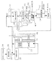
図1において、図示の燃料電池システムは固体酸化物形燃料電池22、比較的低温で作動する第2の燃料電池62、脱硫装置26、燃料エゼクタ28、改質反応器30、一酸化炭素変成器32、33、一酸化炭素酸化反応器66及び二酸化炭素分離装置67を備えている。この燃料電池システムでは、原燃料ガスとして炭化水素を含む燃料、例えば天然ガスが用いられ、例えば、液化天然ガスタンクから天然ガスが供給される。
炭化水素を含む燃料としての原燃料ガス(天然ガス)は、天然ガス供給源34から脱硫装置26に送給され、この脱硫装置26によって、原燃料ガスに含まれている硫黄成分が除去され、硫黄分が除去された原燃料ガスは燃料エゼクタ28を通して改質反応器30に供給される。燃料エゼクタ28を通して原燃料ガスが流れる際に、燃料エゼクタ28の吸引作用により固体酸化物形燃料電池22において燃料電池発電反応が行われた反応燃料ガスの一部が引き込まれ、原燃料ガスに反応燃料ガスの一部が混合される。この燃料エゼクタ28における混合は混合状態での酸素と炭素の元素比が2.0〜2.2の範囲になるように能力調整され、その能力調整は原燃料ガスの圧力調整で行われる。混合された混合燃料ガスは改質反応器30で一部改質された後、固体酸化物形燃料電池22のセルに導入され、発電反応と改質反応が同時に行われる。
固体酸化物形燃料電池22は酸化物イオンを伝導する固体電解質36を備え、この固体電解質36の片側の空気極側に後述するようにして空気が供給され、その他側の燃料極側に一部改質された混合燃料ガスが供給され、燃料電池反応により発電が行われる。この固体酸化物形燃料電池22の燃料側から排出された反応燃料ガスは、その一部が上述したように燃料エゼクタ28に送給され、その残部が一酸化炭素変成器32に導入される。一酸化炭素変成器32、33は導入された反応燃料ガスを変成し、反応燃料ガスに含まれた一酸化炭素が低減される。この際の一酸化炭素変成器33の出口部の温度は160〜200℃程度とする。その後、変成された反応燃料ガスに含まれる一酸化炭素酸化反応器66で一酸化炭素を一酸化炭素酸化反応器に空気又は酸素を供給し選択的に酸化し二酸化炭素にする。
さらにこの反応燃料ガスは二酸化炭素分離装置67で反応燃料ガス中の二酸化炭素が取り除かれる。二酸化炭素以外が除かれた後の反応燃料ガスが、第二の燃料電池24に供給され、同時に第二の燃料電池に空気が供給され、燃料電池反応による発電が行われる。また、二酸化炭素分離装置67の二酸化炭素吸収物から二酸化炭素を放出させるための加熱源として、固体酸化物形燃料電池22の排気を熱交換器46で固体酸化物形燃料電池に供給する空気を加熱した後、供給する。この際、熱交換器46を出た後の固体酸化物形燃料電池の排気を直接、二酸化炭素吸収物から二酸化炭素を放出させるための加熱源とする方法の以外に、水蒸気で代表される加熱媒体を熱交換器46を出た後の固体酸化物形燃料電池の排気で加熱して二酸化炭素吸収物から二酸化炭素を放出させるための加熱源として用いることができる。また、二酸化炭素分離装置を作動させるための加熱源として固体酸化物形燃料電池の排気に加えて、第二の燃料電池24の冷却のために用いた排冷却水もしくは蒸気を用いることで、燃料電池システムの放熱損失が比較的大きい場合においても、二酸化炭素分離装置の作動のために必要な熱量の供給が充足するようになる。なお、二酸化炭素を吸収する吸収物としてはアミン水溶液やアルカリ水溶液を利用することができる。
(他の実施形態)また、なお、固体高分子形燃料電池の代わりにリン酸形燃料電池、もしくはアルカリ形燃料電池を設置してもよい。
【0008】
【実施例および比較例】
実施例として、図1に示した燃料電池システム(固体酸化物形燃料電池と固体高分子形燃料電池を備えた燃料電池システム)を用いた。比較例では、固体酸化物形燃料電池の燃料極側出口の反応燃料ガスのうち、改質反応器に供給する反応燃料ガスを除いた残りの燃料ガスを空気極側出口の排気ガスと混合して燃焼させた。
原燃料としては、以下の組成(容量%)のガスを用いた。
【0009】
【表1】
【0010】
原燃料ガスの供給圧力は0.8MPaであり、このガスを減圧して実施例および比較例の燃料電池システムに供給した。
固体酸化物形燃料電池の燃料側出口ガス温度は約910℃で、固体酸化物形燃料電池内の最高温度は約1000℃であった。なお、作動圧力は大気圧であった。実施例および比較例の燃料電池システムにおいて用いた固体酸化物形燃料電池の出力密度を0.15W/cm2で一定とした際の固体酸化物形燃料電池の燃料利用率とセルあたりの電圧との関係は、表2に示すとおりであった。セル電圧性能の高い平板タイプの固体酸化物形燃料電池を用いている。
【0011】
【表2】
【0012】
実施例として図1の燃料電池システムで発電を行った。作動条件と、発電出力および送電端出力は、表3に示す通りである。
【0013】
【表3】
【0014】
表3に示すように直流発電端効率として71.8%が得られた。表3に示した直流出力から直交変換効率、空気ブロア、ポンプ、制御に用いる内部消費電力を引いた交流送電端効率を表4に示した。400kWが実施例のシステムである。これを5000kWに規模を大きくすると、直交変換効率の向上、空気ブロアとポンプ効率の向上、発電出力に占める制御電力が低下するため、交流送電端効率(低位発熱量基準)を67.7%まで向上させることができる。
【0015】
【表4】
【0016】
また、固体酸化物形燃料電池の燃料利用率を変えた際の直流発電効率を第2 図に示す。また、固体酸化物形燃料電池の燃料利用率と固体酸化物形燃料電池の出力(kW)と固体高分子形燃料電池との出力(kW)比を第 表に示す。図2より、本発明の燃料発電効率を高めるには、固体酸化物形燃料電池の燃料利用率が65〜80%の範囲が高いことがわかる。さらに、表5より、固体酸化物形燃料電池の燃料利用率と固体酸化物形燃料電池の出力(kW)と固体高分子形燃料電池との出力(kW)比が2.25〜4.3間となる条件で高い発電効率が得られることがわかる。
【0017】
【表5】
【0018】
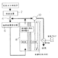
次に比較例として図3の燃料電池システムで発電を行った。作動条件と、発電出力および送電端出力は、表6に示す通りである。
【0019】
【表6】
【0020】
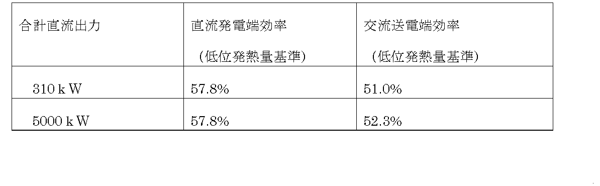
表6に示すように直流発電端効率として57.8%が得られた。表6に示した直流出力から直交変換効率、空気ブロア、制御に用いる内部消費電力を引いた交流送電端効率を表7に示した。310kWが実施例のシステムである。これを5000kWに規模を大きくすると、直交変換効率の向上、空気ブロア効率の向上、発電出力に占める制御電力が低下するため、交流送電端効率(低位発熱量基準)を52.3%まで向上させることができる。
【0021】
【表7】
【0022】
この表4〜表6から理解されるように、実施例では比較例に比して高い発電効率が得られることが確認された。
【0023】
【発明の効果】
本発明の請求項1によれば、固体酸化物形燃料電池で発電および原燃料ガスの改質を行い、第2の燃料電池に反応燃料ガスを送給し、第2の燃料電池でさらに発電を行う構成のシステムで、固体酸化物形燃料電池の排熱を利用する二酸化炭素分離装置を設置することで、第2の燃料電池でより高水素利用率での発電を可能にさせ、燃料電池システム全体の発電効率が高まる。
また、本発明の請求項2によれば、第2の燃料電池リン酸形燃料電池、もしくは固体高分子形電池、もしくはアルカリ形燃料電池を用いることで、燃料電池システムの発電効率が高まる。
また、本発明の請求項3によれば、燃料極側における燃料ガスの最高温度が850℃以上であるので、原燃料の炭化水素中に含まれ、最も分解しにくいメタンが改質反応でほぼすべて分解するため、第2の燃料電池で水素として発電反応に使うことができるため、請求項1、2記載の燃料電池システムの発電効率を高めることができる。
【図面の簡単な説明】
【図1】図1は、本発明に従う固体酸化物形燃料電池システムの実施形態を簡略的に示すシステムブロック図である。
【図2】図2は、実施例に示す固体酸化物形燃料電池の燃料利用率と発電効率との関係を示す図である。
【図3】図3は、比較例に従う固体酸化物形燃料電池システムの実施形態を簡略的に示すシステムブロック図である。
【符号の説明】
22 固体酸化物形燃料電池
62 固体高分子形燃料電池
67 二酸化炭素分離装置[0001]
TECHNICAL FIELD OF THE INVENTION
The present invention relates to a fuel cell system including a solid oxide fuel cell that generates power using a hydrocarbon-based gas such as methane as a fuel, and a second fuel cell that operates at a relatively low temperature.
[0002]
[Prior art]
The solid oxide fuel cell has a structure in which electrodes having a function of oxidizing and reducing fuel gas and oxygen in air are attached to both sides of a solid electrolyte that conducts oxide ions. As a material for the electrolyte, zirconia doped with yttria is generally used. At a high temperature of 700 ° C. to 1000 ° C., hydrogen, carbon monoxide, hydrocarbon in fuel gas and oxygen in oxidant gas are electrically discharged. Electric power is generated by a chemical reaction.
Applications of solid oxide fuel cells include the field of large power plants of 10 MW to several hundred MW in addition to distributed power sources and cogeneration installed in buildings and factories. In the latter case, a plant with a power transmission end power generation efficiency of 55% on a low calorific value basis is commercially operated by a combination of a gas turbine and a steam turbine. The production cost of the system using solid oxide fuel cells, which is said to be higher in production cost than the combination of a gas turbine and a steam turbine, is about 70% at the power transmission end because of its commercial use in large power plants. Is needed. As a measure for this purpose, Reference 1 discloses a design result in which a solid oxide fuel cell is pressurized and combined with a gas turbine to exceed a power transmission end power generation efficiency of 70% based on a lower heating value.
Reference 1 W. L. Lundberg and S.M. E. FIG. Veyo in Solid Oxide Fuel Cells VII ', H. et al. Yokokawa and S.K. C. Singhal (Eds.), P78 The Electrochemical Society Proceedings Series, PV01-16, Pennington, NJ, 2001.
However, the system shown in FIG. 1 in Document 1 has a configuration in which two pressurized solid oxide fuel cells and two gas turbines are connected to an air flow path and an exhaust flow path. It is estimated that it is difficult or very expensive to obtain a working stability of a practical system.
Japanese Patent Application No. 59-146310 discloses a fuel cell system in which a molten carbonate fuel cell, a phosphoric acid fuel cell, and a carbon dioxide separator are combined. In this fuel cell system, the ratio of the reaction amount between the molten carbonate fuel cell and the phosphoric acid fuel cell is about 1: 1. From the ratio of the reaction amounts, it can be seen that the fuel utilization of the first molten carbonate is about 40 to 50%. In a molten carbonate fuel cell, the temperature inside the fuel cell is at most about 650 ° C., 200 ° C. lower than that in a solid oxide fuel cell, and the fuel utilization rate in the molten carbonate fuel cell is low. In the case of about 50%, a considerable amount of methane remains even downstream of the first stage. This is also shown in Table 3 of JP-A-62-274560. Methane is not decomposed downstream of the molten carbonate fuel cell because of its low temperature. When 1 mol of methane remains, the amount of hydrogen corresponding to about 3 mol is reduced as compared with the case where methane does not remain (the remaining amount is 0 mol). In a phosphoric acid fuel cell, since only hydrogen is a component used in the power generation reaction, the remaining methane is generated in the second stage under the condition that a considerable amount of methane remains downstream of the first molten carbonate fuel cell. The fuel cell system is not used in the phosphoric acid fuel cell, and the power generation efficiency of the entire fuel cell system combining the molten carbonate fuel cell and the phosphoric acid fuel cell cannot be sufficiently increased.
[Non-Patent Document 1] L. Lundberg and S.M. E. FIG. Veyo in Solid Oxide Fuel Cells VII ', H. et al. Yokokawa and S.K. C. Singhal (Eds.), P78 The Electrochemical Society Proceedings Series, PV01-16, Pennington, NJ, 2001.
[Patent Document 1] Japanese Patent Application No. 59-146310 [Patent Document 2] Japanese Patent Application Laid-Open No. 62-274560 [Problems to be Solved by the Invention]
As a system for increasing power generation efficiency by further utilizing a fuel electrode side reaction gas of a solid oxide fuel cell at a downstream side, for example, as in a fuel cell system described in Japanese Patent Application No. 2001-336121, a solid oxide fuel cell A fuel cell system is disclosed, in which the fuel electrode side reaction gas is passed through a carbon monoxide converter and then further generated by a fuel cell operating at a low temperature. Since high power generation efficiency can be obtained from a scale of several tens of kW, both electricity and heat generated as cogeneration with high power generation efficiency installed in buildings and factories are used on the demand side. However, when this fuel cell system is used in the field of large power plants, there is no demand to use the heat generated during power generation, so it is necessary to further increase the power generation efficiency.
[0003]
An object of the present invention is to provide a fuel cell that can be used in a large power plant while avoiding the technical difficulties involved in pressurizing the fuel cell and combining it with a gas turbine and the difficulty in ensuring reliability. It is to provide a configuration and conditions that maximize the power generation efficiency of the system.
[0004]
[Means for Solving the Problems]
Means for solving the problems of the present invention are as described in each claim of the claims described above, and specifically, as described below.
The present invention is a reforming reactor for reforming a raw fuel gas containing hydrocarbons, a solid oxide fuel cell for performing a fuel cell power generation reaction, a carbon monoxide converter and a carbon monoxide oxidation reactor, With a carbon dioxide separation device and a second fuel cell that performs a fuel cell power generation reaction at 250 ° C. or less,
The raw fuel gas is mixed with a recycled gas of a part of the reaction fuel gas after performing the fuel cell power generation reaction in the solid oxide fuel cell, and after passing through the reforming reactor, the solid oxide To the solid oxide fuel cell, and in both the reforming reactor and the solid oxide fuel cell, the reforming reaction of hydrocarbons is performed by using heat accompanying the fuel cell power generation reaction in the solid oxide fuel cell. While performing the fuel cell power generation reaction with the solid oxide fuel cell, the remaining reaction fuel gas used for the recycling is transferred from the solid oxide fuel cell to the carbon monoxide converter and the carbon monoxide oxidation reaction. After reducing the concentration of carbon monoxide in the reaction fuel gas, the gas from which carbon dioxide has been removed by the carbon dioxide separator is fed to the fuel side of the second fuel cell, Perform a battery reaction, the solid The utilization rate of the raw fuel gas in the compound fuel cell is set at 65 to 80%, and the carbon dioxide separation device includes a regeneration step of carbon dioxide emission by heat, and the carbon dioxide absorption material after carbon dioxide absorption Fuel cell system, characterized in that exhaust gas of the solid oxide fuel cell or a heating medium obtained by heat exchange with exhaust gas of the solid oxide fuel cell is used as a heating source for releasing carbon dioxide from the fuel cell system. It is.
According to the present invention, power is generated by the solid oxide fuel cell, and hydrogen gas from which carbon dioxide is separated is further generated by the second fuel cell at 250 ° C. or lower. The following advantages are obtained as compared with the conventional system.
First, by lowering the fuel utilization of the solid oxide fuel cell from 80 to 85% in the conventional method, the hydrogen concentration near the outlet increases, and the power generation characteristics are improved. That is, the generated voltage at the same current density is improved.
Second, the fuel-side gas taken out of the solid oxide fuel cell, that is, the reaction fuel gas, is reformed by absorbing the heat generated by the cell reaction. That is, in the conventional system, part of the heat generated by the exhaust of the solid oxide fuel cell is converted into an excessive amount of hydrocarbons with respect to the power generated by the solid oxide fuel cell. It is used and converted to electricity in a fuel cell that operates at a relatively low temperature. Further, when the maximum temperature in the solid oxide fuel cell is 850 ° C. or higher, methane, which is most difficult to decompose among hydrocarbons, is almost completely decomposed and reformed, which also reduces the power generation efficiency of the fuel cell system. It is advantageous in increasing.
Third, the concentration of hydrogen and carbon dioxide is increased and the concentrations of water vapor and carbon monoxide are reduced by performing a monoxide shift reaction on the outlet fuel gas of the solid oxide fuel cell at high temperature operation. Most of the chemical energy that carbon monoxide had at the outlet of the solid oxide fuel cell is held by the fuel gas as hydrogen. Further, in the present invention, carbon dioxide is separated by the carbon dioxide separation device, and the composition of the fuel-side inlet of the second fuel cell operating at a relatively low temperature is hydrogen and water vapor. When air is added in the carbon monoxide oxidation reactor, a little nitrogen is added. In the case of this fuel composition, the proportion of hydrogen that can be used in the second fuel cell can be set at a high value of 85 to 99% (hydrogen utilization rate of 85 to 99%). This is also advantageous for increasing power generation efficiency.
Fourth, the carbon dioxide separation device includes a step of regenerating carbon dioxide emission by heat, and the solid oxide fuel is used as a heating source for releasing carbon dioxide from a carbon dioxide absorbent after absorbing carbon dioxide. Since the heating medium obtained by heat exchange with the exhaust gas of the cell or the exhaust gas of the solid oxide fuel cell can be used, the power generation efficiency of the fuel cell system is lost despite the operation of the carbon dioxide separator. There is almost no. In the present invention, the second fuel cell is a phosphoric acid fuel cell, a polymer electrolyte fuel cell, or an alkaline fuel cell. In such a fuel cell system, a phosphoric acid fuel cell, a polymer electrolyte fuel cell, or an alkaline fuel cell is preferable as the second fuel cell utilizing the reaction fuel gas of the solid oxide fuel cell. By combining such a fuel cell with a physical fuel cell, the power generation efficiency of the entire fuel cell system can be increased. Note that only in the case of an alkaline fuel cell, a pretreatment for previously removing carbon dioxide in the air supplied to the second fuel cell is required.
In such a fuel cell system, it is preferable that the maximum temperature of the fuel gas on the fuel side of the solid oxide fuel cell be 850 ° C. or higher. Of these, methane having the highest decomposition temperature can be almost completely decomposed by the reforming reaction at a sufficient engineering rate in the reforming reactor and the solid oxide fuel cell. Methane cannot be decomposed in the carbon monoxide converter, and if the temperature of the solid oxide fuel cell is low, the concentration of hydrogen that can be used for the power generation reaction in the second fuel cell decreases, and the entire fuel cell system Power generation efficiency is reduced.
[0005]
Further, in the present invention, the exhaust of the solid oxide fuel cell and the cooling of the second fuel cell are performed by a heating source for releasing carbon dioxide from the carbon dioxide absorbent after absorbing the carbon dioxide in the carbon dioxide separation device. It is characterized by using waste cooling water or steam used for the cooling. By using exhaust cooling water or steam of the second fuel cell in addition to exhaust gas of the solid oxide fuel cell as a heating source for operating the carbon dioxide separation device, heat radiation loss of the fuel cell system is relatively large. Even in such a case, the supply of heat required for the operation of the carbon dioxide separation device is satisfied.
[0006]
BEST MODE FOR CARRYING OUT THE INVENTION
Hereinafter, embodiments of the present invention will be described with reference to the drawings.
[0007]
An embodiment of the fuel cell system according to the first embodiment will be described with reference to FIG.
In FIG. 1, the fuel cell system shown is a solid oxide fuel cell 22, a second fuel cell 62 operating at a relatively low temperature, a desulfurizer 26, a fuel ejector 28, a reforming reactor 30, a carbon monoxide converter. 32, 33, a carbon monoxide oxidation reactor 66 and a carbon dioxide separator 67 are provided. In this fuel cell system, a fuel containing hydrocarbons, for example, natural gas is used as a raw fuel gas, and for example, natural gas is supplied from a liquefied natural gas tank.
Raw fuel gas (natural gas) as a fuel containing hydrocarbons is sent from a natural gas supply source 34 to a desulfurization device 26, which removes a sulfur component contained in the raw fuel gas, The raw fuel gas from which the sulfur content has been removed is supplied to the reforming reactor 30 through the fuel ejector 28. When the raw fuel gas flows through the fuel ejector 28, a part of the reaction fuel gas that has undergone the fuel cell power generation reaction in the solid oxide fuel cell 22 is drawn in by the suction action of the fuel ejector 28 and reacts with the raw fuel gas. Part of the fuel gas is mixed. The mixing in the fuel ejector 28 is adjusted so that the element ratio of oxygen and carbon in the mixed state is in the range of 2.0 to 2.2, and the adjustment of the capacity is performed by adjusting the pressure of the raw fuel gas. After the mixed fuel gas is partially reformed in the reforming reactor 30, it is introduced into the cells of the solid oxide fuel cell 22, and the power generation reaction and the reforming reaction are performed simultaneously.
The solid oxide fuel cell 22 includes a solid electrolyte 36 that conducts oxide ions. Air is supplied to one air electrode side of the solid electrolyte 36 as described later, and a portion is supplied to the other fuel electrode side. The reformed mixed fuel gas is supplied, and power generation is performed by a fuel cell reaction. A part of the reaction fuel gas discharged from the fuel side of the solid oxide fuel cell 22 is sent to the fuel ejector 28 as described above, and the remainder is introduced into the carbon monoxide converter 32. The carbon monoxide converters 32 and 33 convert the introduced reaction fuel gas, and the carbon monoxide contained in the reaction fuel gas is reduced. At this time, the temperature at the outlet of the carbon monoxide converter 33 is set to about 160 to 200 ° C. Thereafter, air or oxygen is supplied to the carbon monoxide oxidation reactor in the carbon monoxide oxidation reactor 66 contained in the converted reaction fuel gas to selectively oxidize the carbon monoxide to carbon dioxide.
Further, from the reaction fuel gas, carbon dioxide in the reaction fuel gas is removed by the carbon dioxide separation device 67. The reaction fuel gas from which the components other than carbon dioxide have been removed is supplied to the second fuel cell 24, and at the same time, air is supplied to the second fuel cell, whereby power is generated by the fuel cell reaction. Further, as a heating source for releasing carbon dioxide from the carbon dioxide absorbent of the carbon dioxide separator 67, air supplied from the solid oxide fuel cell 22 to the solid oxide fuel cell by the heat exchanger 46 is used as a heating source. After heating, supply. At this time, in addition to a method in which the exhaust gas of the solid oxide fuel cell after leaving the heat exchanger 46 is directly used as a heating source for releasing carbon dioxide from the carbon dioxide absorbent, a heating method represented by steam is used. The medium can be used as a heating source for heating the exhaust gas of the solid oxide fuel cell after leaving the heat exchanger 46 to release carbon dioxide from the carbon dioxide absorbent. Further, in addition to the exhaust gas of the solid oxide fuel cell as a heating source for operating the carbon dioxide separation device, by using waste cooling water or steam used for cooling the second fuel cell 24, Even in the case where the heat loss of the battery system is relatively large, the supply of the amount of heat necessary for operating the carbon dioxide separation device is satisfied. In addition, an amine aqueous solution or an alkaline aqueous solution can be used as the absorbent that absorbs carbon dioxide.
(Other Embodiments) A phosphoric acid fuel cell or an alkaline fuel cell may be provided instead of the polymer electrolyte fuel cell.
[0008]
[Examples and Comparative Examples]
As an example, the fuel cell system shown in FIG. 1 (a fuel cell system including a solid oxide fuel cell and a polymer electrolyte fuel cell) was used. In the comparative example, of the reaction fuel gas at the fuel electrode side outlet of the solid oxide fuel cell, the remaining fuel gas excluding the reaction fuel gas supplied to the reforming reactor was mixed with the exhaust gas at the air electrode side outlet. And burned.
As a raw fuel, a gas having the following composition (volume%) was used.
[0009]
[Table 1]
[0010]
The supply pressure of the raw fuel gas was 0.8 MPa, and this gas was reduced in pressure and supplied to the fuel cell systems of Examples and Comparative Examples.
The fuel-side outlet gas temperature of the solid oxide fuel cell was about 910 ° C., and the maximum temperature in the solid oxide fuel cell was about 1000 ° C. The working pressure was atmospheric pressure. When the output density of the solid oxide fuel cells used in the fuel cell systems of Examples and Comparative Examples was kept constant at 0.15 W / cm2, the fuel utilization rate of the solid oxide fuel cells and the voltage per cell were measured. The relationship was as shown in Table 2. A flat plate type solid oxide fuel cell having high cell voltage performance is used.
[0011]
[Table 2]
[0012]
As an example, power was generated by the fuel cell system of FIG. The operating conditions, the power generation output and the power transmission end output are as shown in Table 3.
[0013]
[Table 3]
[0014]
As shown in Table 3, a DC power generation end efficiency of 71.8% was obtained. Table 4 shows the AC transmission end efficiency obtained by subtracting the orthogonal conversion efficiency, the air blower, the pump, and the internal power consumption used for control from the DC output shown in Table 3. 400 kW is the system of the embodiment. If the scale is increased to 5000 kW, the orthogonal conversion efficiency is improved, the air blower and pump efficiency are improved, and the control power in the power generation output is reduced. Can be improved.
[0015]
[Table 4]
[0016]
FIG. 2 shows the DC power generation efficiency when the fuel utilization of the solid oxide fuel cell was changed. Table 1 shows the fuel utilization of the solid oxide fuel cell and the ratio of the output (kW) of the solid oxide fuel cell to the output (kW) of the polymer electrolyte fuel cell. From FIG. 2, it can be seen that the fuel utilization of the solid oxide fuel cell is high in the range of 65 to 80% in order to increase the fuel power generation efficiency of the present invention. Furthermore, from Table 5, the fuel utilization of the solid oxide fuel cell, the output (kW) of the solid oxide fuel cell, and the output (kW) ratio of the solid polymer fuel cell to the power (kW) are 2.25 to 4.3. It can be seen that high power generation efficiency can be obtained under the conditions between the two.
[0017]
[Table 5]
[0018]
Next, as a comparative example, power was generated by the fuel cell system of FIG. The operating conditions, the power generation output and the power transmission end output are as shown in Table 6.
[0019]
[Table 6]
[0020]
As shown in Table 6, a DC power generation end efficiency of 57.8% was obtained. Table 7 shows the AC transmission end efficiency obtained by subtracting the orthogonal conversion efficiency, the air blower, and the internal power consumption used for control from the DC output shown in Table 6. 310 kW is the system of the embodiment. If the scale is increased to 5000 kW, the orthogonal conversion efficiency is improved, the air blower efficiency is improved, and the control power occupying the power generation output is reduced. Therefore, the AC transmission end efficiency (lower heating value standard) is improved to 52.3%. be able to.
[0021]
[Table 7]
[0022]
As understood from Tables 4 to 6, it was confirmed that higher power generation efficiency was obtained in Examples than in Comparative Examples.
[0023]
【The invention's effect】
According to the first aspect of the present invention, the power generation and the reforming of the raw fuel gas are performed by the solid oxide fuel cell, the reaction fuel gas is supplied to the second fuel cell, and the power generation is further performed by the second fuel cell. By installing a carbon dioxide separation device using the exhaust heat of the solid oxide fuel cell, the second fuel cell enables power generation at a higher hydrogen utilization rate, and the fuel cell The power generation efficiency of the entire system increases.
According to the second aspect of the present invention, the power generation efficiency of the fuel cell system is increased by using the second phosphoric acid fuel cell, the solid polymer electrolyte battery, or the alkaline fuel cell.
Further, according to the third aspect of the present invention, since the maximum temperature of the fuel gas on the fuel electrode side is 850 ° C. or more, methane contained in the hydrocarbon of the raw fuel and hardly decomposed is substantially removed by the reforming reaction. Since all of them are decomposed, they can be used in the power generation reaction as hydrogen in the second fuel cell, so that the power generation efficiency of the fuel cell system according to claims 1 and 2 can be improved.
[Brief description of the drawings]
FIG. 1 is a system block diagram schematically showing an embodiment of a solid oxide fuel cell system according to the present invention.
FIG. 2 is a diagram illustrating a relationship between a fuel utilization rate and a power generation efficiency of the solid oxide fuel cell according to the embodiment.
FIG. 3 is a system block diagram schematically showing an embodiment of a solid oxide fuel cell system according to a comparative example.
[Explanation of symbols]
22 solid oxide fuel cell 62 polymer electrolyte fuel cell 67 carbon dioxide separation device