JP2004172007A - Rotary electronic parts - Google Patents
Rotary electronic parts Download PDFInfo
- Publication number
- JP2004172007A JP2004172007A JP2002338281A JP2002338281A JP2004172007A JP 2004172007 A JP2004172007 A JP 2004172007A JP 2002338281 A JP2002338281 A JP 2002338281A JP 2002338281 A JP2002338281 A JP 2002338281A JP 2004172007 A JP2004172007 A JP 2004172007A
- Authority
- JP
- Japan
- Prior art keywords
- fixed
- click
- flange
- grease
- slider piece
- Prior art date
- Legal status (The legal status is an assumption and is not a legal conclusion. Google has not performed a legal analysis and makes no representation as to the accuracy of the status listed.)
- Withdrawn
Links
Images
Landscapes
- Rotary Switch, Piano Key Switch, And Lever Switch (AREA)
- Adjustable Resistors (AREA)
Abstract
Description
【0001】
【発明の属する技術分野】
本発明は種々の電子機器に使用される回転型電子部品に関する。
【0002】
【従来の技術】
従来より、エアコンディショナー等種々の電子機器をコントロールするための電子部品として回転型エンコーダ等の回転型電子部品が用いられている。
【0003】
このような従来の回転型電子部品について説明すると、前記回転型電子部品は、中心部分に貫通孔が形成された基部と、前記基部における貫通孔の外縁を基端として軸方向に延設された固定側筒部とを有する固定体を備えており、この基部の表面には、導電パターンが形成されている。
【0004】
また、この回転型電子部品は、前記固定体の筒部に対して回転可能に装着された回転側筒部と、この回転側筒部の一端縁から外方向に延設された鍔部とを有する回転体を備えている。この回転体の鍔部の底面には、摺動子片が固着されており、この摺動子片は、前記回転体が回転するとき前記導電パターンに摺接されながら前記回転体とともに回転するようになっている。さらに、前記鍔部の表面には、複数のクリック用溝が形成されている。
【0005】
また、前記回転型電子部品は、前記各クリック用溝に対向するように配設されたクリック用部材としての環状のクリック用板ばねを備えており、前記固定体、前記回転体および前記クリック用板ばねは、枠体によって一体に保持されている。そして、前記回転型電子部品は、前記枠体によって種々の電子機器に取り付けられていた(例えば、特許文献1)。
【0006】
このような回転型電子部品においては、回転トルクを重くして作動力を得るため、前記固定体の筒部と前記回転体の筒部との摺動部および前記クリック用板ばねと前記各クリック用溝との摺接部に粘性の高いグリスを充填していた。一方、前記摺動子片と前記導電パターンとの摺接部には低い粘性のグリスを充填し、ブラシ等によってこのグリスをかきわけることにより、前記摺動子片と前記導電パターンとの接触不良を防止していた。
【0007】
【特許文献1】
特開2002−110001号公報
【0008】
【発明が解決しようとする課題】
しかし、前記回転型電子部品においては、前記回転体を前記固定体に装着する際、前記固定側筒部の表面に塗布した粘性の高いグリスが前記固定体の基部表面に流れ込み、前記摺動子片と前記導電パターンとの摺接部に到達してしまうおそれがあった。そして、このような粘性の高いグリスはブラシ等によってかきわけることができないので、前記摺動子片と前記導電パターンとの接触不良が発生してしまい、この結果回転型電子部品の信頼性を損なう場合があるという問題が生じていた。
【0009】
一方、上記問題を解決するために、前記固定側筒部と前記回転体側筒部との摺動部に粘性の低いグリスを充填することが考えられるが、この場合には、前記回転型電子部品において、回転トルクを重くして作動力を得るという目的を達成することができなくなってしまう。
【0010】
本発明はこれらの点に鑑みてなされたものであり、各部に最適なグリスを使用することにより、信頼性を損なうことなく、かつ最適な作動力を得ることができる回転型電子部品を提供することを目的とする。
【0011】
【課題を解決するための手段】
前記目的を達成するため、本発明に係る回転型電子部品は、基部およびこの基部の内周部分から軸方向に延設された固定側軸部を有する固定体と、前記固定側軸部に対して回転可能に外側に装着された回転側軸部およびこの回転側軸部の一端縁から外周方向に延設され前記基部に対向するように形成された鍔部を有する回転体と、前記固定体および前記回転体を一体に保持する枠体と、前記基部の表面または前記鍔部の裏面に装着されたクリック用部材と、前記基部の表面または前記鍔部の裏面のいずれか他方に前記クリック用部材に摺動するように形成されたクリック用溝と、前記鍔部の表面またはこの鍔部の表面に対向する位置に装着された摺動子片と、前記鍔部の表面またはこの鍔部の表面に対向する位置のいずれか他方に前記摺動子片に摺動するように配置された導体パターンとを有することを特徴とする。
【0012】
この本発明に係る回転型電子部品によれば、回転体における鍔部よりも上方に摺動子片と導電パターンとの摺動部が位置するので、固定側軸部と回転側軸部との摺動面に充填された高い粘性のグリスが、前記摺動子片と前記導電パターンとの摺動部に流れ込むということを防止することができる。また、固定側軸部と回転側軸部との摺動面に用いられる高い粘性のグリスの塗布量が多い場合であっても、このグリスはクリック用部材と各クリック用溝との摺動部に流れてこの摺動部のグリスとして有効に用いることができる。そして、前記摺動子片と前記導電パターンとの摺動部には、低い粘性のグリスを用いることができるので、この結果、各部に最適なグリスを使用することができる。
【0013】
また、本発明に係る他の回転型電子部品は、前記鍔部の表面に対向するように装着された絶縁基板を有し、前記鍔部の表面に、前記摺動子片を装着し、前記絶縁基板の裏面に、前記導体パターンを形成したことを特徴とする。
【0014】
この本発明に係る他の回転型電子部品によれば、回転体における鍔部の表面に対向するように絶縁基板が装着されているので、摺動子片と導電パターンとの摺動部への防塵を図ることができる。また、摺動子片と導電パターンとの摺動面は導電パターンを形成した面となるが、この本発明に係る他の回転型電子部品によれば、前記導電パターンを絶縁基板に設けているので、導電パターンを鍔部の表面に設けるのと比較して、固定側軸と回転側軸との摺動面に充填された高い粘性のグリスが前記摺動面に付着してしまうのをより確実に防止することができる。
【0015】
【発明の実施の形態】
以下、本発明に係る回転型電子部品の実施形態を図1から図3を参照して説明する。ここで、本実施形態においては、回転型エンコーダを例にして説明する。
【0016】
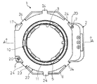
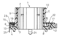
図1は、本実施形態に係る回転型エンコーダの一実施形態を示す平面図であり、図2は、図1に示す回転型エンコーダを示すA−Aにおける断面側面図である。
【0017】
図1および図2に示すように、回転型エンコーダ1は、絶縁材である合成樹脂等の材料によって構成された固定体2を有している。この固定体2は、横断面が略八角形状であって内側に円形状の貫通孔3を有する基部4と、この基部4における前記貫通孔3の外縁を基端として軸方向上方に延設された固定側軸部としての固定側筒部5と、前記基部4の外縁を基端として軸方向上方に前記固定側筒部5よりも短い高さ寸法によって延設された側壁部6とを備えている。また、前記固定体2における基部4の表面には、位置決め用の2つの小突起(図示せず)が突設されており、さらに前記固定体における側壁部の表面縁には、位置決め用の2つの小突起7が突設されている。
【0018】
また、前記固定体2における基部4の表面には、クリック用部材としての環状のクリック用板ばね8が配設されており、このクリック用板ばね8の外周縁における前記各小突起の形成位置に対応する位置には、突部(図示せず)が外方向に突設されている。これら各突部には、位置決め用孔(図示せず)が前記各小突起に対応するように形成されており、そして、前記クリック用板ばね8は、前記固定体2の基部4に形成された各小突起と前記各位置決め用孔とを嵌合させることにより、前記固定体2の基部4の表面に固定されるようになっている。
【0019】
さらに、前記回転型エンコーダ1は、絶縁材である合成樹脂等の材料によって構成された回転体10を有する。この回転体10は、前記固定側筒部5の外側に回転可能に装着された回転側軸部としての回転側筒部11と、この回転側筒部11の一端縁から前記回転側筒部11の軸を中心として外方向に前記固定側筒部11に対して直交する角度によって延設された鍔部12とを備えている。この鍔部12は、前記固定体2の表面であって前記側壁部6の内側に嵌る程度の大きさに形成されており、また、この鍔部12の表面には、4つの小突起(図示せず)が突設され、さらにこの鍔部12の裏面には、複数のクリック用溝13が形成されている。
【0020】
さらにまた、前記回転体10における鍔部12の表面には、半環状の摺動子片15が配設されており、この摺動子片15における前記鍔部12の各小突起に対応する位置には、それぞれ位置決め用孔(図示せず)が形成されている。そして、前記摺動子片15は、前記回転体10の各小突起と前記各位置決め用孔とを嵌合させることにより、前記回転体10の鍔部12の表面に固定されるようになっている。
【0021】
また、前記回転型エンコーダ1は、前記固定体2の基部4と同じ大きさの略八角形状の絶縁基板17を有し、前記絶縁基板17の中心部には、前記回転体10における回転側筒部11の外面に嵌る大きさの貫通孔18が形成されている。さらに、前記絶縁基板17の裏面には、導電パターン19が形成されており、また前記絶縁基板17における前記固定体2の側壁部6に突設された各小突起7に対応する位置には、それぞれ位置決め用孔20が形成されている。そして、この絶縁基板17は、前記固定体2の側壁部6に形成された各小突起7と前記各位置決め用孔20とを嵌合させることにより、前記固定体2の側壁部6の表面に固定されるようになっており、この状態において前記回転体10をさせたとき、前記導電パターン19が前記摺動子片15に摺接されるようになっている。
【0022】
さらに、前記回転型エンコーダ1は、金属板により構成された枠体22を有しており、この枠体22は、前記回転体10の回転側筒部11の外面に嵌る大きさの略環状の枠本体23と、前記枠本体23の外周縁から下方に延設される複数の取付部24と、前記枠本体23の外周縁から下方に延設される複数の端子25とを備えている。そして、前記枠体22は、前記枠本体23が前記回転側筒部11の外側に嵌めるように装着されて前記各取付部24により前記固定体2と、前記回転体10と、前記絶縁基板17とを一体に保持するようになっており、この回転型エンコーダ1は、これら各取付部24により種々の電子機器に取り付けられるようになっていた。
【0023】
次に、本実施形態に係る回転型エンコーダ1の組み立て工程について説明する。
【0024】
まず、クリック用板ばね8を、その各位置決め用孔が固定体2における基部4の表面の各小突起に嵌合するように前記基部4の表面に装着して固定する。
【0025】
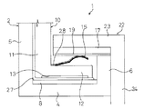
次に、前記固定体2の固定側筒部5の外面および前記クリック用板ばね8の表面に、図3に示すように、粘性の高いグリス27を塗布し、続いて、回転体10を回転側筒部11の内面を前記固定側筒部5の外面に摺接させながら、鍔部12の各クリック用溝13が前記クリック用板ばね8に当接するように、回転体10を前記固定体2における基部4の表面に装着する。このとき、前記固定側筒部5の外面に塗布されていた粘性の高いグリス27は、前記回転側筒部11の内面に摺接されることにより、前記固定側筒部5と前記回転側筒部11の摺動面全体に均一に広がるとともに、余ったグリス27は、前記クリック用板ばね8の表面に流される。
【0026】
さらに、摺動子片15を、その各位置決め用孔が回転体10における鍔部12の各小突起に嵌合するように前記鍔部12の表面に装着して固定した後、この摺動子片15の表面に、低い粘性のグリス28を塗布する。続いて、絶縁基板17を、その各位置決め用孔20が前記固定体2における側壁部6の各小突起7に嵌合し、前記摺動子片15の表面が前記絶縁基板17の導電パターン19に当接するように前記鍔部12の表面に装着する。
【0027】
そして、枠体22を、枠本体23裏面が前記絶縁基板2の表面に当接し、各取付部24の裏面が前記固定体2における側壁部6の表面に当接するように装着して、回転型エンコーダ1を組み立てる。
【0028】
このような回転型エンコーダ1は、前記回転体10を回転させると、前記各クリック溝13が固定体2に固定されたクリック用板ばね8に摺動されるとともに、前記回転体10に固定された摺動子片15が絶縁基板17の導電パターン19に摺動され、これによりパルス信号を発生する。
【0029】
本実施形態によれば、前記回転体10における鍔部12よりもに前記摺動子片15と前記導電パターン19との摺動部が位置するので、前記固定側筒部と前記回転側筒部との摺動面に充填された高い粘性のグリスが、従来のように前記摺動子片と前記導電パターンとの摺動部に流れ込むということを防止することができる。また、前記固定側筒部5と前記回転側筒部11との摺動面に用いられる高い粘性のグリス27の塗布量が多い場合であっても、このグリス27は前記クリック用板ばね8と前記各クリック用溝13との摺動部に流れてこの摺動部のグリスとして用いることができる。そして、前記摺動子片15と前記導電パターン19との摺動部には、低い粘性のグリス28を用いることができるので、この結果、各部に最適なグリス27,28を使用することができる。
【0030】
したがって、本回転型エンコーダ1は、前記固定側筒部5と前記回転側筒部11との摺動面、および前記クリック用板ばね8と前記各クリック用溝13との摺動部に、高い粘性のグリス27を用いることにより、回転トルクが重く最適な作動力を得ることができる。また、前記固定側筒部5と前記回転側筒部11との摺動面に用いられるグリス27の塗布量が多い場合であっても、このグリス27を前記クリック用板ばね8と前記各クリック用溝13との摺動部のグリス27として用いることができるので、前記グリス27の塗布量の管理が容易となる。さらに、前記摺動子片15と前記導電パターン19との摺動部に低い粘性のグリス28を利用することができるので、前記摺動子片15と前記導電パターン19との接触不良を防止することができ、これにより、この回転型エンコーダ1の信頼性を高めることができる。
【0031】
また、前記回転体10における鍔部12の表面に対向するように絶縁基板17が装着されているので、前記摺動子片15と前記導電パターン19との摺動部への防塵を図ることができる。このため、前記摺動子片15と前記導電パターン19との接触不良を一層防止することができる。
【0032】
なお、本発明は前記実施形態に限定されるものではなく、必要に応じて種々変更することが可能である。
【0033】
例えば、本実施形態においては、前記固定体2における基部4の表面にクリック用板ばね8が装着され、前記回転体10における鍔部12の裏面に各クリック用溝13が形成されているが、これに限定されず、前記基部の表面に複数のクリック用溝を形成し、前機器部の裏面にクリック用部材を装着するものであってもよい。
【0034】
また、前記回転体10における鍔部12の表面に摺動子片15が装着され、その摺動子片15の表面に当接するように前記導電パターン19が形成された絶縁基板17が装着されているが、これに限定されず、前記鍔部の表面に導電パターンを形成し、前記絶縁基板の裏面に摺動子片を装着するものであってもよい。
【0035】
さらに、本実施形態における回転型エンコーダ1は、中空型のものであるが、これに限定されるものではない。
【0036】
また、本実施形態においては回転型電子部品として回転型エンコーダ1用いて説明したが、これに限定されず、例えば可変抵抗器に適用してもよい。その場合には、抵抗対パターンによって導電パターンを形成すればよい。
【0037】
【発明の効果】
以上述べたように、本発明に係る回転型電子部品によれば、回転型電子部品は、固定側軸と回転側軸との摺動面、およびクリック用部材と各クリック用溝との摺動部に、高い粘性のグリスを用いることにより、回転トルクが重く最適な作動力を得ることができる。また、固定側軸と回転側軸との摺動面に用いられるグリスの塗布量が多い場合であっても、このグリスを前記クリック用部材と前記各クリック用溝との摺動部のグリスとして用いることができるので、前記グリスの塗布量の管理が容易となる。さらに、摺動子片と導電パターンとの摺動部に低い粘性のグリスを利用することができるので、摺動子片と導電パターンとの接触不良を防止することができ、これにより、この回転型電子部品の信頼性を高めることができる。
【0038】
また、本発明に係る他の回転型電子部品によれば、摺動子片と導電パターンとの摺動部への防塵を図ることができるので、摺動子片と導電パターンとの接触不良を一層防止することができる。また、導電パターンに高い粘性のグリスが付着してしまうのを確実に防止することができるので、より摺動子片と導電パターンとの接触不良を防止することができる。これにより、前記回転型電子部品の信頼性をより高めることができる。
【図面の簡単な説明】
【図1】本発明に係る回転型電子部品の一実施形態を示す平面図
【図2】図1に示す回転型電子部品のA−Aにおける断面側面図
【図3】図1に示す回転型電子部品の固定側筒部と回転側筒部との間にグリスが充填されている場合を示す断面概略図
【符号の説明】
1 回転型エンコーダ
2 固定体
4 基部
5 固定側筒部
6 側壁部
8 クリック用板ばね
10 回転体
11 回転側筒部
12 鍔部
13 クリック用溝
15 摺動子片
17 絶縁基板
19 導電パターン
22 枠体
23 枠本体
27 粘性の高いグリス
28 粘性の低いグリス[0001]
TECHNICAL FIELD OF THE INVENTION
The present invention relates to a rotary electronic component used for various electronic devices.
[0002]
[Prior art]
2. Description of the Related Art Conventionally, rotary electronic components such as a rotary encoder have been used as electronic components for controlling various electronic devices such as an air conditioner.
[0003]
To describe such a conventional rotary electronic component, the rotary electronic component is extended in the axial direction with a base having a through-hole formed in a central portion and an outer edge of the through-hole in the base as a base end. A fixed body having a fixed side tubular portion is provided, and a conductive pattern is formed on a surface of the base.
[0004]
In addition, the rotary electronic component includes a rotation-side cylinder portion rotatably mounted on the cylinder portion of the fixed body, and a flange portion extending outward from one edge of the rotation-side cylinder portion. Having a rotating body. A slider piece is fixed to the bottom surface of the flange of the rotor, and the slider piece rotates with the rotor while slidingly contacting the conductive pattern when the rotor rotates. It has become. Further, a plurality of click grooves are formed on the surface of the flange.
[0005]
Further, the rotary electronic component includes an annular click leaf spring as a click member disposed so as to face each of the click grooves, and the fixed body, the rotating body and the click body. The leaf spring is integrally held by the frame. And the said rotary electronic component was attached to various electronic devices by the said frame (for example, patent document 1).
[0006]
In such a rotary electronic component, a sliding portion between the tubular portion of the fixed body and the tubular portion of the rotating body, the leaf spring for click, and The viscous grease was filled in the sliding contact with the groove. On the other hand, the sliding contact portion between the slider piece and the conductive pattern is filled with low-viscosity grease, and this grease is separated by a brush or the like, thereby causing poor contact between the slider piece and the conductive pattern. Had been prevented.
[0007]
[Patent Document 1]
JP-A-2002-110001
[Problems to be solved by the invention]
However, in the rotating electronic component, when the rotating body is mounted on the fixed body, highly viscous grease applied to the surface of the fixed side cylindrical portion flows into the base surface of the fixed body, and the slider There is a possibility that the sliding contact portion between the piece and the conductive pattern may be reached. And since such highly viscous grease cannot be separated by a brush or the like, poor contact between the slider piece and the conductive pattern occurs, and as a result, the reliability of the rotary electronic component is impaired. There was a problem that sometimes.
[0009]
On the other hand, in order to solve the above-described problem, it is conceivable to fill a sliding portion between the fixed-side tubular portion and the rotating body-side tubular portion with low-viscosity grease. In this case, it becomes impossible to achieve the purpose of obtaining the operating force by increasing the rotational torque.
[0010]
The present invention has been made in view of these points, and provides a rotary electronic component that can obtain an optimal operating force without impairing reliability by using an optimal grease for each part. The purpose is to:
[0011]
[Means for Solving the Problems]
In order to achieve the above object, a rotary electronic component according to the present invention includes a fixed body having a base portion and a fixed side shaft portion extending in an axial direction from an inner peripheral portion of the base portion, A rotating body having a rotating side shaft portion rotatably mounted on the outside and a flange portion extending in an outer peripheral direction from one end edge of the rotating side shaft portion and formed so as to face the base portion; and the fixed body. And a frame body that integrally holds the rotating body, a click member mounted on the front surface of the base or the back surface of the flange, and the click member on one of the front surface of the base and the back surface of the flange. A click groove formed so as to slide on the member, a slider piece mounted on the surface of the flange portion or a position facing the surface of the flange portion, and a surface of the flange portion or the flange portion. The slider is located at one of the other positions facing the surface. And having a arranged conductive patterns to slide.
[0012]
According to the rotary electronic component of the present invention, since the sliding portion between the slider piece and the conductive pattern is positioned above the flange portion of the rotating body, the fixed-side shaft portion and the rotating-side shaft portion It is possible to prevent high-viscosity grease filled in the sliding surface from flowing into the sliding portion between the slider piece and the conductive pattern. Even when the amount of high-viscosity grease used on the sliding surface between the fixed-side shaft portion and the rotation-side shaft portion is large, the grease is applied to the sliding portion between the click member and each of the click grooves. And can be effectively used as grease for the sliding portion. In addition, since low-viscosity grease can be used for a sliding portion between the slider piece and the conductive pattern, optimal grease can be used for each part.
[0013]
Further, another rotary electronic component according to the present invention includes an insulating substrate mounted so as to face the surface of the flange portion, and mounting the slider piece on the surface of the flange portion, The conductive pattern is formed on the back surface of the insulating substrate.
[0014]
According to the other rotary electronic component according to the present invention, since the insulating substrate is mounted so as to face the surface of the flange portion of the rotating body, the sliding portion between the slider piece and the conductive pattern can be used. Dust protection can be achieved. In addition, the sliding surface between the slider piece and the conductive pattern is a surface on which the conductive pattern is formed. According to another rotary electronic component according to the present invention, the conductive pattern is provided on the insulating substrate. Therefore, compared to the case where the conductive pattern is provided on the surface of the flange portion, it is more likely that the highly viscous grease filled in the sliding surface between the fixed shaft and the rotating shaft will adhere to the sliding surface. It can be reliably prevented.
[0015]
BEST MODE FOR CARRYING OUT THE INVENTION
An embodiment of a rotary electronic component according to the present invention will be described below with reference to FIGS. Here, in the present embodiment, a rotary encoder will be described as an example.
[0016]
FIG. 1 is a plan view showing an embodiment of a rotary encoder according to the present embodiment, and FIG. 2 is a cross-sectional side view taken along AA of the rotary encoder shown in FIG.
[0017]
As shown in FIGS. 1 and 2, the
[0018]
An annular
[0019]
Further, the
[0020]
Furthermore, a
[0021]
In addition, the
[0022]
Further, the
[0023]
Next, an assembly process of the
[0024]
First, the
[0025]
Next, as shown in FIG. 3, a highly
[0026]
Further, the
[0027]
Then, the
[0028]
In such a
[0029]
According to the present embodiment, since the sliding portion between the
[0030]
Therefore, the
[0031]
Further, since the insulating
[0032]
Note that the present invention is not limited to the above embodiment, and can be variously modified as needed.
[0033]
For example, in the present embodiment, the
[0034]
Further, a
[0035]
Furthermore, the
[0036]
Further, in the present embodiment, the description has been given using the
[0037]
【The invention's effect】
As described above, according to the rotary electronic component according to the present invention, the rotary electronic component has a sliding surface between the fixed shaft and the rotary shaft, and a sliding surface between the click member and each of the click grooves. By using high viscosity grease for the part, the rotational torque is heavy and an optimal operating force can be obtained. Further, even when the amount of grease used on the sliding surface between the fixed side shaft and the rotating side shaft is large, the grease is used as the grease of the sliding portion between the click member and each of the click grooves. Since the grease can be used, the amount of the grease applied can be easily managed. Further, since low-viscosity grease can be used in the sliding portion between the slider piece and the conductive pattern, it is possible to prevent poor contact between the slider piece and the conductive pattern, and thereby, The reliability of the mold electronic component can be improved.
[0038]
Further, according to another rotary electronic component according to the present invention, it is possible to prevent dust on a sliding portion between the slider piece and the conductive pattern. It can be further prevented. In addition, since highly viscous grease can be reliably prevented from adhering to the conductive pattern, poor contact between the slider piece and the conductive pattern can be further prevented. Thereby, the reliability of the rotary electronic component can be further improved.
[Brief description of the drawings]
FIG. 1 is a plan view showing an embodiment of a rotary electronic component according to the present invention; FIG. 2 is a cross-sectional side view taken along AA of the rotary electronic component shown in FIG. 1; FIG. Cross-sectional schematic diagram showing a case where grease is filled between a fixed-side tubular portion and a rotating-side tubular portion of an electronic component.
DESCRIPTION OF
Claims (2)
前記固定側軸部に対して回転可能に外側に装着された回転側軸部およびこの回転側軸部の一端縁から外周方向に延設され前記基部に対向するように形成された鍔部を有する回転体と、
前記固定体および前記回転体を一体に保持する枠体と、
前記基部の表面または前記鍔部の裏面に装着されたクリック用部材と、
前記基部の表面または前記鍔部の裏面のいずれか他方に前記クリック用板部材に摺動するように形成されたクリック用溝と、
前記鍔部の表面またはこの鍔部の表面に対向する位置に装着された摺動子片と、
前記鍔部の表面またはこの鍔部の表面に対向する位置のいずれか他方に前記摺動子片に摺動するように配置された導体パターンとを有することを特徴とする回転型電子部品。A fixed body having a base portion and a fixed side shaft portion extending in the axial direction from an inner peripheral portion of the base portion;
A rotation-side shaft portion rotatably mounted on the outside with respect to the fixed-side shaft portion; and a flange portion extending from one end edge of the rotation-side shaft portion in an outer peripheral direction and formed to face the base portion. A rotating body,
A frame body that integrally holds the fixed body and the rotating body,
A click member mounted on the front surface of the base portion or the back surface of the flange portion,
A click groove formed to slide on the click plate member on one of the front surface of the base portion and the back surface of the flange portion,
A slider piece mounted on the surface of the flange or at a position facing the surface of the flange,
A rotating electronic component, comprising: a conductor pattern disposed so as to slide on the slider piece on the other of the surface of the flange portion and a position facing the surface of the flange portion.
前記鍔部の表面に前記摺動子片を装着し、前記絶縁基板の裏面に前記導体パターンを形成したことを特徴とする請求項1に記載の回転型電子部品。Having an insulating substrate mounted so as to face the surface of the flange portion,
The rotary electronic component according to claim 1, wherein the slider piece is mounted on a surface of the flange portion, and the conductor pattern is formed on a back surface of the insulating substrate.
Priority Applications (1)
| Application Number | Priority Date | Filing Date | Title |
|---|---|---|---|
| JP2002338281A JP2004172007A (en) | 2002-11-21 | 2002-11-21 | Rotary electronic parts |
Applications Claiming Priority (1)
| Application Number | Priority Date | Filing Date | Title |
|---|---|---|---|
| JP2002338281A JP2004172007A (en) | 2002-11-21 | 2002-11-21 | Rotary electronic parts |
Publications (1)
| Publication Number | Publication Date |
|---|---|
| JP2004172007A true JP2004172007A (en) | 2004-06-17 |
Family
ID=32701555
Family Applications (1)
| Application Number | Title | Priority Date | Filing Date |
|---|---|---|---|
| JP2002338281A Withdrawn JP2004172007A (en) | 2002-11-21 | 2002-11-21 | Rotary electronic parts |
Country Status (1)
| Country | Link |
|---|---|
| JP (1) | JP2004172007A (en) |
Cited By (2)
| Publication number | Priority date | Publication date | Assignee | Title |
|---|---|---|---|---|
| JP2007123459A (en) * | 2005-10-27 | 2007-05-17 | Alps Electric Co Ltd | Rotating electrical component |
| JP2017045640A (en) * | 2015-08-27 | 2017-03-02 | アルプス電気株式会社 | Input device |
-
2002
- 2002-11-21 JP JP2002338281A patent/JP2004172007A/en not_active Withdrawn
Cited By (2)
| Publication number | Priority date | Publication date | Assignee | Title |
|---|---|---|---|---|
| JP2007123459A (en) * | 2005-10-27 | 2007-05-17 | Alps Electric Co Ltd | Rotating electrical component |
| JP2017045640A (en) * | 2015-08-27 | 2017-03-02 | アルプス電気株式会社 | Input device |
Similar Documents
| Publication | Publication Date | Title |
|---|---|---|
| KR100356195B1 (en) | Electronic parts of press turn-operating type | |
| JP3631990B2 (en) | Slip ring and slip ring integrated motor | |
| CN204088146U (en) | The rotating mechanism of rotary switch and rotary switch | |
| CN100587860C (en) | Rotary Electrical Parts | |
| JP7209476B2 (en) | electronic components | |
| JPS5818246Y2 (en) | Rotating electrical parts | |
| JP3677362B2 (en) | Rotating electrical parts | |
| JP4037741B2 (en) | Rotating electronic components | |
| JP2004103288A (en) | Rotary operation type electric component | |
| JP2004172042A (en) | Rotary switch | |
| JP4297764B2 (en) | Switch device | |
| JPH09232110A (en) | Electronic component with click mechanism | |
| CN216971947U (en) | Cap screwing mechanism and electrical equipment comprising same | |
| JP2001257106A (en) | Potary electric part | |
| JP2000348567A (en) | Rotary electrical part | |
| JP3870040B2 (en) | Rotating electrical parts | |
| JPH11233311A (en) | Knob fitting structure | |
| JP4570560B2 (en) | Electronic components | |
| JPH0636012U (en) | Turning device | |
| JP3701554B2 (en) | Rotary encoder | |
| JPH0534084Y2 (en) | ||
| JP3710359B2 (en) | Hollow shaft variable resistor | |
| JP6647801B2 (en) | Rotary electronic components | |
| JP2003124008A (en) | Variable resistor | |
| JPH0429525Y2 (en) |
Legal Events
| Date | Code | Title | Description |
|---|---|---|---|
| A621 | Written request for application examination |
Free format text: JAPANESE INTERMEDIATE CODE: A621 Effective date: 20050517 |
|
| A977 | Report on retrieval |
Free format text: JAPANESE INTERMEDIATE CODE: A971007 Effective date: 20080104 |
|
| A131 | Notification of reasons for refusal |
Free format text: JAPANESE INTERMEDIATE CODE: A131 Effective date: 20080122 |
|
| A761 | Written withdrawal of application |
Free format text: JAPANESE INTERMEDIATE CODE: A761 Effective date: 20080221 |