JP2004176404A - Cylindrical component capable of changing tip diameter - Google Patents
Cylindrical component capable of changing tip diameter Download PDFInfo
- Publication number
- JP2004176404A JP2004176404A JP2002343698A JP2002343698A JP2004176404A JP 2004176404 A JP2004176404 A JP 2004176404A JP 2002343698 A JP2002343698 A JP 2002343698A JP 2002343698 A JP2002343698 A JP 2002343698A JP 2004176404 A JP2004176404 A JP 2004176404A
- Authority
- JP
- Japan
- Prior art keywords
- peripheral wall
- diameter
- fin
- fins
- cylindrical
- Prior art date
- Legal status (The legal status is an assumption and is not a legal conclusion. Google has not performed a legal analysis and makes no representation as to the accuracy of the status listed.)
- Granted
Links
- 230000002093 peripheral effect Effects 0.000 claims abstract description 85
- 238000000034 method Methods 0.000 claims description 15
- 230000001105 regulatory effect Effects 0.000 claims description 5
- 238000007599 discharging Methods 0.000 claims description 3
- 238000012840 feeding operation Methods 0.000 claims description 2
- 239000000463 material Substances 0.000 description 20
- 239000011440 grout Substances 0.000 description 19
- 210000002435 tendon Anatomy 0.000 description 16
- 239000003673 groundwater Substances 0.000 description 8
- 230000000694 effects Effects 0.000 description 6
- 239000004570 mortar (masonry) Substances 0.000 description 5
- 238000007790 scraping Methods 0.000 description 5
- 230000003247 decreasing effect Effects 0.000 description 3
- 238000010586 diagram Methods 0.000 description 3
- 239000011347 resin Substances 0.000 description 3
- 229920005989 resin Polymers 0.000 description 3
- 238000010276 construction Methods 0.000 description 2
- 230000001276 controlling effect Effects 0.000 description 2
- 238000005304 joining Methods 0.000 description 2
- 238000012856 packing Methods 0.000 description 2
- 239000004568 cement Substances 0.000 description 1
- 230000006835 compression Effects 0.000 description 1
- 238000007906 compression Methods 0.000 description 1
- 230000008602 contraction Effects 0.000 description 1
- 238000005553 drilling Methods 0.000 description 1
- 238000003306 harvesting Methods 0.000 description 1
- 238000003780 insertion Methods 0.000 description 1
- 230000037431 insertion Effects 0.000 description 1
- 238000004519 manufacturing process Methods 0.000 description 1
- 239000008267 milk Substances 0.000 description 1
- 210000004080 milk Anatomy 0.000 description 1
- 235000013336 milk Nutrition 0.000 description 1
- 238000000465 moulding Methods 0.000 description 1
- 238000003825 pressing Methods 0.000 description 1
- 230000002265 prevention Effects 0.000 description 1
- 239000010802 sludge Substances 0.000 description 1
- XLYOFNOQVPJJNP-UHFFFAOYSA-N water Substances O XLYOFNOQVPJJNP-UHFFFAOYSA-N 0.000 description 1
Images






Landscapes
- Piles And Underground Anchors (AREA)
Abstract
Description
【0001】
【発明の属する技術分野】
この発明は、先端径の変更が可能な筒状部材に関する。
【0002】
【従来の技術】
【非特許文献1】社団法人 日本アンカー協会 ホームページ
上記ウェブサイト(http://www.japan−anchor.or.jp/)に、従来地盤中に設置したアンカー体と構造物に取り付けたアンカー頭部をテンドンと呼ばれる引張材で連結し、アンカー体の引き抜き抵抗によって地滑り土塊の滑動を引き止め、構造物の安定を図るグラウンドアンカー工法が記載されている。
【0003】
そして上記グラウンドアンカー工法は、テンドンにプレストレスをかけることによって、テンドンの伸びの少ない段階、すなわち地すべり等による変形量が少ない段階での滑動抑止効果を向上させることができるという特徴を持ち、斜面安定,構造物の転倒・浮き上り防止,仮設山留め・土留め等土木建築分野において広く利用されている。
【0004】
上記グラウンドアンカー工法を、上記ウェブサイトのグラウンドアンカー施工手順に従って簡単に説明すると、
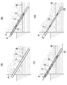
1.図13(a)に示されるように、不安定地盤表面に形成された構造物(擁壁)Aから定着対象地盤(基盤)Bまで削孔機等によって掘削した削孔Cに、ケーシングパイプDを挿入する
2.図13(b)に示されるように、ケーシングパイプD内にセメントミルク又はモルタル等からなるグラウト材Gを充填し、さらにテンドンFを挿通する
3.図13(c)に示されるように、ケーシングパイプDを一部引き抜き、グラウト材Gを加圧注入し、基盤Bにアンカー体G’を形成せしめ、ケーシングを引き抜く
4.図13(d)に示されるように、アンカー体G’と構造物Aとの間で、テンドンFにプレストレスをかけ、アンカー体G’を介して基盤Bと構造物Aとによって不安定地盤層を圧縮する
というものである。
【0005】
【発明が解決しようとする課題】
しかし上記グラウンドアンカー工法の施行方法においては、ケーシング内のグラウト材Gの排除作業ができないため、ケーシングを引き抜くとテンドンと不安定地盤層の圧縮すべき部分との間の間隙の確保ができず現実にはテンドンFのプレストレスによる不安定地盤層の圧縮をほとんど行うことができないという問題点があった。
【0006】
【課題を解決するための手段】
上記課題を解決するための本発明の先端径の変更が可能な筒状部材は、交互に又は順次側端側がスライド可能に接合し合う多数のフィンを、連続した周壁を形成するように円形配置し、上記周壁の先端側の径が弾力的に縮小又は拡大可能な構造とし、周壁の先端側の内側に空間を形成してなることを第1の特徴としている。
【0007】
第2に各フィンが外周方向に湾曲又は屈曲し、全体として先端側が拡大した円錐筒形をなすことを特徴としている。
【0008】
第3に各フィンの側端が、隣接する他の側端と互いにスライド可能に接合し合うことを特徴としている。
【0009】
第4に隣接するフィンが、周方向において相互に一部重複して接合し合うことにより全体として外周部と密閉された周壁を形成することを特徴としている。
【0010】
第5に周壁の外周側に外挿され、径を拡大縮小させることにより、周壁の先端側の径の拡大縮小を行うリング状の規制部材を設けたことを特徴としている。
【0011】
第6に周壁の外周側に、周壁の軸心に沿ってスライド自在に外装され、周壁に対して挿脱されることによって、周壁の先端側の径の拡大縮小を行う筒状の規制部材を設けたことを特徴としている。
【0012】
第7にフィンが、円筒形の筒又は孔内を軸心方向に摺動移動する際に、先端部分が筒状体の内周面の付着物を周壁の内側に導入案内するフィン6と、先端部分が軸心方向に湾曲又は屈曲し、該先端部分が筒又は孔の内周面に接し、上記送り込み作業時に筒又は孔内の軸方向移動を案内するフィン7とから構成されることを特徴としている。
【0013】
第8に周壁の内側の空間と連通し、周壁の内側に導入された付着物を筒又は穴の外部に排出せしめる中空のパイプを筒状部材3の基端部側に取り付けたことを特徴としている。
【0014】
第9に筒がグラウンドアンカー工法におけるケーシングパイプDであることを特徴としている。
【0015】
【発明の実施の形態】
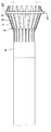
図1は、本発明の筒状部材を用いて構成した、グラウンドアンカー工法のケーシングパイプ内からグラウト材を排出させて抜き取る排出管1の側面図であり、該排出管1は、パイプ2の先端に本発明の筒状部材3が取り付けられた構造となっている。
【0016】
そして前述のグラウンドアンカー工法の図13(c)の作業工程において、グラウト材Gの加圧注入後、ケーシングDを抜き取る前に、図2に示されるように本排出管1をケーシングパイプD内に挿入することによって、ケーシングパイプD内のグラウト材Gを抜き取ることができ、これによりケーシングDが抜き取られた後、排出管1がテンドンFの外周をカバーし、テンドンFと排出管1のパイプ2との間に間隙が形成せしめられる。
【0017】
このとき排出管1は不安定地盤層側となるが、テンドンFと排出管1とは一体的とはならないため、テンドンFの外周の間隙がテンドンFと不安定地盤層との間の間隙となり、これによりテンドンFにかけられるプレストレスによって基盤Bと構造物Aとの間に不安定地盤層が圧縮され、効果的なグラウンドアンカー工法が行われる。
【0018】
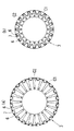
次に上記筒状部材3の構造について説明する。該筒状部材3は図3に示されるように、パイプ2に取り付けられる円筒状の本体4の端面側に2種類のフィン6,7が、隣接するフィンが、隣接する他の側端と互いにスライド可能に相互に一部重複して接合し合い、全体として外周部と密閉され、内側に空間が形成された周壁を形成するように、円形配置されて構成されている。
【0019】
そして各フィン6,7は、図4に示されるように、フィン6の先端が弦となる円C1の径が、本体4の外径より大きくなるように、中間部部分においてパイプ2の外周側となる本体4の外周側に屈曲又は湾曲され、全体として先端側が拡大した円錐筒形をなしている。
【0020】
また一方の種類のフィン7は、各フィン7の先端が弦となる円C2の径が、上記C1の径より小さく、且つ本体4の外径より大きくなるように、先端側が本体4の中心に向かって屈曲又は湾曲されている。
【0021】
そして筒状部材3は、筒状部材3を構成する上記各パーツ4,6,7を全て、樹脂によって成形することによって、全体が樹脂製となっており、図4(a),(b)に示されるように、隣接するフィンが互いにスライドし合い、筒状部材3の先端側(両フィン6,7の先端側)の径が弾力的に縮小又は拡大する。
【0022】
次に筒状部材3の本体4の構造について説明する。該本体4は図5に示されるように、中空の円筒形状をなし、一方の端面4aに上記一方の種類のフィン7を挿入して取り付け支持するフィン取付突起8が所定のピッチで円形に配列されて設けられている。このとき上記フィン取付突起8は、板状をなし、先端側にフィン7の挿入用のスリット9が穿設された構造となっている。
【0023】
また上記フィン取付突起8間は、他方の種類のフィン6を取付けるフィン取付突起11を構成しており、隣接するフィン取付突起8の対向する隣接面間にフィン6を挿入して取り付けることが可能となっている。
【0024】
一方本体4の内周面には段部13(図9参照)が形成されており、フィン取付突起8側の内径d1(図9参照)が、フィン取付突起8の反対側の内径d2(図9参照)に比較して小径となっている。
【0025】
次に上記フィン7の構造について説明する。図6に示されるように、該フィン7は、くの字状に湾曲又は屈曲したベース板14の裏面の中心に長手方向にリブ16が設けられ、該リブ16の一端(先端)側の上端に上記ベース板14に平行に、且つ上記ベース板14の先端から突出するようにプレート17が固定されている。
【0026】
そしてプレート17の先端がベース板14の先端の外側において、ベース板14側に湾曲又は屈曲され、さらにプレート17における先端側の表面に、ベース板14の裏面に至るリブ18が設けられた構成となっている。
【0027】
このときベース板14及びプレート17は、ともにベース板14の先端部分までは、ベース板14の先端に向かって幅が徐々に増加し、さらにプレート17のみベース板14の先端に相対する部分より先端の幅が、先端に向かって徐々に減少し、プレート17は先鋭となっている。そして上記構成によりガイドフィン7におけるリブ16の左右両側にはプレート17とベース板14とによってスリット19が形成されている。
【0028】
そして図7(a),(b)に示されるように、上記リブ16における他端(基端)側を上記フィン取付突起8のスリット9に、本体4の内側から挿入することによって、フィン7が本体4の外周方向に湾曲又は屈曲した状態で本体4から突出して取り付けられ、本体4の端部4a側に所定のピッチで円形に配列される。
【0029】
このときフィン7の本体4の外周方向への湾曲又は屈曲は、プレート17の湾曲又は屈曲部分が頂部となり、さらにプレート17の上記形状により、プレート17の先端が、上記頂部から本体4の中心に向かって湾曲又は屈曲することとなる。
【0030】
次に上記フィン6の構造について説明する。図8に示されるように、該フィン6は、くの字状に屈曲又は湾曲した掻込み板21の裏面に、湾曲部分から一端(基端)側に向かって長手方向にリブ22が設けられ、該リブ22の上面に掻込み板21に平行に平行板23が固定された構造となっている。これによりリブ22の左右には平行板23と掻込み板21とによってスリット24が形成される。
【0031】
そして図7(a),(c)に示されるように、各スリット24に隣接するフィン取付突起8をそれぞれ挿入することによって、プレート21の湾曲又は屈曲により、フィン6は先端側が本体4の外側方に湾曲又は屈曲して本体4から突出するように取り付けられる。
【0032】
これによりフィン6が、フィン7の間に位置して本体4の端部4aに所定のピッチで円形に配列され、つまり両種類のフィン6,7が交互に円形配置される。なお図7(b)はフィン7を実線で、フィン6を想像線で記載したものであり、図7(c)フィン7を想像線で、フィン6を実線でそれぞれ記載したものである。
【0033】
このときフィン6の先端位置はフィン7におけるベース板14の先端位置と概ね一致しており、上記フィン6とフィン7の本体4への取り付けによって、フィン7のプレート17の先端部分はフィン6及びベース板14の先端より突出し、上記のように本体4の中心に向かって湾曲又は屈曲する。
【0034】
これにより筒状部材3の先端はプレート17の先端からなる山部と、隣接するプレート17の先端部分の稜線とプレート21の先端とからなる谷部が連続し、山部の基部(谷部の先端)が略最大径となり、且つ山部は先端に向かって内側に屈曲又は湾曲している。
【0035】
また図7に示されるように、フィン6は、本体4に取り付けられた状態で、プレート21の両側端部が、隣接するフィン7のスリット19に挿入され、プレート21とプレート17とは、プレート21の側端面21aとガイドフィン7のリブ16との間に間隙を設けた状態で重複している。
【0036】
なおフィン7におけるリブ16の基端部側には、リブ16をフィン取付突起8のスリット9に挿入した状態でフィン取付突起8の外周面から突出する部分に、径方向からの抜けを防止する平面視で矢印状をなす突起部26が設けられている。また本体4への取り付け状態におけるフィン6の上記突起部26に相対する部分には突起部26と係合し、且つ突起部26の先端側への抜けを防止する係合部27が設けられている。
【0037】
これにより該突起部26によってフィン7のフィン取付突起8からの径方向からの抜けが防止されている他、係合部27と突起部26の係合によりフィン7の先端側への抜けも防止され、本筒状部材3が使用中に分解するようなことはない。
【0038】
筒状部材3は以上のように構成されており、先端側の外径は、フィン6のプレート21の側端面21aとフィン7のリブ16とが当接するまで円滑に縮小する。またフィン7のフィン取付突起8への挿入状態が、比較的緩い(がたが大きい)ことに加え、樹脂製の各フィン6,7,ガイドフィン取付突起8,本体4の弾性力により、複雑な各フィン6,7の支持構造等を構成することなく、フィン7の最低限の遊嵌支持によって、筒状部材3の外径は、縮小状態から円滑に拡大して復帰し、すなわち筒状部材3の先端側の外径は、弾力的に且つ円滑に拡縮する。
【0039】
また筒状部材3の周壁は、フィン6のプレート21とフィン7のベース板14及びプレート17とによって形成されるため、初期状態でプレート21とベース板14とが重複していることにより、外径の拡縮時に周壁が不連続となることはなく、筒状部材3は両端部以外は閉じられた状態を維持して外径の拡縮が行われる。
【0040】
そして上記排出管1は、パイプ2を本体4に、フィン取付突起8の反対側の端部から挿入し、パイプ2の先端部を前述の段部13の端面に当接させ固定することによって構成されており、パイプ2の先端に筒状部材3が、パイプ2と同心に位置決めされ、筒状部材3の周壁の内部とパイプ2の内部が連通されている。
【0041】
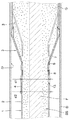
上記構造により、前述のように排出管1を使用したグラウンドアンカー工法において、ケーシングパイプDからグラウト材を掻き出す際は、まず上記のように筒状部材3にパイプ2を差込み両者を固定し、図9に示されるように上記排出管1をグラウト材Gを挿入したケーシングパイプD内に挿入し、パイプ部2の軸心方向に移動させる。
【0042】
このとき筒状部材3は、湾曲又は屈曲した頂部がケーシングパイプDの内周面に接するように弾力的に最大径が縮小し、最大径部を構成するフィン6の先端がケーシングパイプDの内周面D’側の付着物となるグラウト材Gを筒状部材3の周壁の内部に導入案内して送り込む。
【0043】
このとき筒状部材3の内側に湾曲又は屈曲する上記山部と谷部の稜線部分がグラウト材Gを案内して筒状部材3内に送り込み導入し、これによりケーシングパイプD内のグラウト材Gは効率よく筒状部材3の内部に導入されて送り込まれ、そして筒状部材3の内部に導入されたグラウト材Gは、パイプ2内のテンドンFとの間の隙間SSを通ってパイプ2の端部から外部に排出される。
【0044】
このときケーシングパイプD内に接合部による段差等が存在し、異径部分がある場合も、フィン6におけるプレート21がフィン7のスリット19内をスライドすることによって、筒状部材3の外径が前述のように円滑に拡縮し、フィン7の頂部がケーシングパイプDの内周面D’に容易且つ円滑に倣う。
【0045】
これにより筒状部材3は、外径がケーシングパイプDの内径に沿ったサイズに変形し、ケーシングパイプDの内周面に接し、ケーシングパイプD内のグラウト材Gを円滑に排出することができる。このとき筒状部材3の周壁には、前述のように不連続部分が存在しないため、上記グラウト材Gの排出作業時に筒状部材3の周壁からグラウト材が漏れ出すことはない。
【0046】
またフィン6が、フィン7のスリット19間をスライドするため、フィン6のスライドはスリット19によってガイドされ、周壁に隙間ができない筒状部材3の円滑な拡縮が行われる。
【0047】
なお本掻込管1は、パイプ2,筒状部材3の本体4,フィン6,フィン7によって構成されているため、分解して各パーツの交換を容易に行うことができる他、コンパクトに持ち運びすることができる。
【0048】
上記本掻込管1は、以上のように筒状体の内周面側の付着物を、該内周面に接触しながら送込む又は掻き取ることができるため、上記ケーシングパイプD内のグラウト材Gの送り出し排出の他、煙突、上下水管、その他プラントのヘドロ状物のドレン管等の内部の付着物の除去作業等にも使用することができる。
【0049】
一方井戸等の孔内に本筒状部材3を挿入し、筒状部材3(フィン6,7)の弾性力によって位置決めしてパッキン部材の基礎部材とすることができる。例えば図10に示すように、表面の地層31の下方に、汚染地下水流動層32,良質地下水流動層33が複数段の地層となっている地盤に井戸を掘る場合等に使用することができる。
【0050】
この場合図示しないパイプ状の押込み部材によって、フィン6,7の先端が孔30の開口部又は孔の底部を向くように、本筒状部材3を挿入し、汚染地下水流動層32と良質地下水流動層33の境界部分に対応する位置に位置決めし、孔30内の汚染地下水に対応する部分をモルタルM等で埋めることによって、孔30内への汚染地下水の浸入を防止することができる。
【0051】
このとき筒状部材3を順次挿入する際、次の筒状部材3の挿入前にモルタルMを注入し、次の筒状部材3を挿入する際に、挿入される筒状部材3の上方側のモルタルMを筒状部材3とパイプを介して排出させることによって、2つの筒状部材3の間をモルタルMで埋めることができる。
【0052】
そして各筒状部材3を貫通して井戸のパイプ34を挿入し、良質地下水流動層33に対応する部分にストレーナ36を設けることによって、パイプ34から良質な地下水を汲み上げることができる。
【0053】
一方図11に示されるように、筒状部材3の周壁の外周側に、フィン6,7の先端側に、アクチュエータ41によって径を拡大縮小させることができるリング(規制部材)42を外挿し、リング42の径を拡大縮小させることにより、筒状部材3の周壁の先端側の径の拡大縮小を行わせるように構成することもできる。
【0054】
また図12に示されるように、本筒状部材3をアーム43の先端に取り付け、該アーム43及び本体4の外周に、周壁に対して挿脱される筒部材(規制部材)44を、スラストベアリング45を介してスライド自在に外嵌させ、筒部材44を周壁に対して挿脱させることによって、筒状部材3の周壁の先端側の径の拡大縮小を行わせるように構成することもできる。
【0055】
この場合、筒部材44は電動シリンダ等のアクチュエータ17に取り付けられており、該アクチュエータ47によってスライドさせられる。また筒部材44側又はアーム43側にはセンサ46が設けられており、該センサ46によって筒部材44のスライド位置をコントロールすることが可能となっている。
【0056】
そして上記いずれの場合も、アクチュエータ41,47の作動をコントロールすることによって、周壁の先端側の径の拡大縮小をコントロールすることができ、これにより生産ラインや医療機器のパーツ捕捉用のロボットハンドや、農作業用の収穫物・間引き物の捕捉用のロボットハンド等の把持装置として、筒状部材3を使用することができる。
【0057】
【発明の効果】
以上のように構成される本発明の構造によると、連続した周壁を形成する多数のフィンがそれぞれ先端側の径を拡縮させる方向に動くため、先端側の径が円滑に拡大又は縮小する。このとき各フィンを外周方向に湾曲又は屈曲させ、筒状部材を全体として先端側が拡大した円錐筒形とすることによって、径の縮小を円滑に行わせ、且つ復元力を高めることが可能となる。
【0058】
また各フィンの側端を、隣接する他の側端と互いにスライド可能に接合し合う構成とすることによって、径の拡大縮小がより円滑に行われ、特に隣接するフィンが、周方向において相互に一部重複して接合し合うことにより全体として外周部と密閉された周壁を形成する構成とすることによって、径の拡大時に周壁に隙間ができることを防止することができる。
【0059】
そして周壁の外周側にリング状又は筒状の規制部材を設け、周壁の先端側の内径のサイズをコントロールすることによって、生産ラインや医療機器のパーツ捕捉用のロボットハンドや、農作業用の収穫物・間引き物の捕捉用のロボットハンド等の把持装置として使用することができるという効果がある。
【0060】
一方本筒状部材を円筒形の筒や孔等に、フィンを筒や孔の内周面に押接させた状態で挿入して位置決めすることができ、例えば孔内に穴の内周面にフィンをほぼ密着させて挿入して位置決めすることによってパッキン部材の基礎部材とすることができるという効果もある。
【0061】
さらに本筒状部材を円筒形の筒や孔等に、フィンを筒や孔の内周面に押接させた状態で挿入し、軸心方向に摺動させることもでき、これにより筒や孔の内周面の付着物をフィンが周壁内に導入案内して送込み、筒又は孔内の上記付着物を効率よく除去し、筒や孔の内周面の清掃を円滑に行うことができるという効果がある。
【0062】
この際筒や孔の内周壁に段部等が存在する場合でも、周壁の先端側の径の円滑な拡大縮小によって、フィンが上記段部等に倣って接し、付着物の除去を円滑に行うとともに、本筒状部材が筒や孔内に詰まること等も防止される。
【0063】
一方周壁の内部に連通するパイプを設けることによって、パイプを介して上記付着物を外部に円滑に排出することができ、例えばグラウンドアンカー工法におけるケーシングパイプに対して本筒状部材を使用することができる。
【0064】
この場合ケーシングパイプ内のグラウト材を外部に送り出し、テンドンの外周に空間を形成させることによって、テンドンにかけられるプレストレスにより効果的なグラウンドアンカー工法を行うことができるという効果がある。
【図面の簡単な説明】
【図1】排出管の側面図である。
【図2】排出管を使用したグラウト材の掻き出し作業状態を示す概要図である。
【図3】筒状部材の斜視図である。
【図4】筒状部材の正面図であり、(a)が拡大時、(b)が縮小時を示す。
【図5】筒状部材の本体の斜視図である。
【図6】一方の種類のフィン単体の(a)は平面図,(b)は正面図,(c)は底面図である。
【図7】両フィンの挿入状態を示し、(a)が正面図,(b),(c)がいずれか一方のフィンを実線で、他方のフィンを想像線で記載した側面図である。
【図8】他方の種類のフィン単体の(a)は、平面図、(b)は正面図,(c)は底面図,(d)は側面図である。
【図9】ケーシングパイプ内のグラウト材の掻き取り作業状態を示す断面図である。
【図10】本筒状部材を井戸に応用した状態を示すイメージ図である。
【図11】リングを使用したロボットハンドに応用した場合の筒状部材の側面図である。
【図12】筒部材を使用したロボットハンドに応用した場合の筒状部材の側面図である。
【図13】(a)〜(d)は、従来のグラウンドアンカー工法を順次示した概要図である。
【符号の説明】
3 筒状部材
6 フィン
7 フィン
D ケーシングパイプ[0001]
TECHNICAL FIELD OF THE INVENTION
The present invention relates to a tubular member whose tip diameter can be changed.
[0002]
[Prior art]
[Non-Patent Document 1] The Japan Anchor Association homepage The above website (http://www.japan-anchor.or.jp/) has an anchor body conventionally installed in the ground and an anchor head attached to a structure. A ground anchor method is described, in which the landslides are connected by a tensile member called a tendon, and the sliding of the landslide mass is stopped by the pull-out resistance of the anchor body to stabilize the structure.
[0003]
The ground anchor method has a feature that, by applying prestress to tendon, it is possible to improve the effect of suppressing slippage at a stage where tendon elongation is small, that is, at a stage where the amount of deformation due to landslide or the like is small. It is widely used in the field of civil engineering and construction, such as prevention of overturning and lifting of structures, temporary retaining and earth retaining.
[0004]
When the ground anchor method is briefly described according to the ground anchor construction procedure on the website,
1. As shown in FIG. 13 (a), a casing pipe D is drilled from a structure (retaining wall) A formed on the unstable ground surface to a ground (base) B to be fixed by a drilling machine or the like.
[0005]
[Problems to be solved by the invention]
However, in the above-mentioned ground anchor method, since the grout material G in the casing cannot be removed, when the casing is pulled out, a gap between the tendon and the portion of the unstable ground layer to be compressed cannot be secured. Has a problem that the unstable ground layer can hardly be compressed due to the prestress of tendon F.
[0006]
[Means for Solving the Problems]
In order to solve the above-mentioned problem, the cylindrical member capable of changing the tip diameter according to the present invention has a large number of fins that are joined alternately or sequentially so that the side ends thereof are slidably arranged in a circular shape so as to form a continuous peripheral wall. The first feature is that the peripheral wall has a structure in which the diameter on the distal end side can be elastically reduced or enlarged, and a space is formed inside the distal end side of the peripheral wall.
[0007]
The second feature is that each fin is curved or bent in the outer peripheral direction, and as a whole, has a conical cylindrical shape whose tip end side is enlarged.
[0008]
Third, a side end of each fin is slidably joined to another adjacent side end.
[0009]
Fourthly, the adjacent fins are partially overlapped and joined to each other in the circumferential direction to form a peripheral wall that is hermetically sealed with the outer peripheral portion as a whole.
[0010]
Fifth, the present invention is characterized in that a ring-shaped regulating member which is extrapolated to the outer peripheral side of the peripheral wall and expands / contracts the diameter to increase / decrease the diameter at the distal end side of the peripheral wall is provided.
[0011]
Sixth, a cylindrical regulating member is provided on the outer peripheral side of the peripheral wall so as to be slidable along the axis of the peripheral wall, and is inserted into and removed from the peripheral wall to enlarge or reduce the diameter of the distal end side of the peripheral wall. It is characterized by having been provided.
[0012]
Seventh, when the fin slides in a cylindrical tube or hole in the axial direction, the
[0013]
Eighth, a hollow pipe that communicates with the space inside the peripheral wall and discharges extraneous matter introduced inside the peripheral wall to the outside of the cylinder or the hole is attached to the base end side of the
[0014]
Ninth, the casing is a casing pipe D in the ground anchor method.
[0015]
BEST MODE FOR CARRYING OUT THE INVENTION
FIG. 1 is a side view of a
[0016]
Then, in the work process of FIG. 13 (c) of the ground anchor method described above, after the grout material G is injected under pressure and before the casing D is extracted, the
[0017]
At this time, the
[0018]
Next, the structure of the
[0019]
As shown in FIG. 4, each
[0020]
One type of the
[0021]
The entirety of the
[0022]
Next, the structure of the
[0023]
A
[0024]
On the other hand, a step 13 (see FIG. 9) is formed on the inner peripheral surface of the
[0025]
Next, the structure of the
[0026]
A configuration in which the distal end of the
[0027]
At this time, both the
[0028]
As shown in FIGS. 7A and 7B, the other end (base end) of the
[0029]
At this time, the curved or bent portion of the
[0030]
Next, the structure of the
[0031]
Then, as shown in FIGS. 7A and 7C, the
[0032]
As a result, the
[0033]
At this time, the tip positions of the
[0034]
As a result, the tip of the
[0035]
As shown in FIG. 7, when the
[0036]
At the base end side of the
[0037]
Thus, the
[0038]
The
[0039]
Further, since the peripheral wall of the
[0040]
The
[0041]
With the above structure, in the ground anchor method using the
[0042]
At this time, the maximum diameter of the
[0043]
At this time, the ridges of the ridges and valleys that curve or bend inside the
[0044]
At this time, even if there is a step due to the joining portion in the casing pipe D and there is a different diameter portion, the outer diameter of the
[0045]
As a result, the outer diameter of the
[0046]
In addition, since the
[0047]
Since the scraping
[0048]
As described above, the scraping
[0049]
On the other hand, the
[0050]
In this case, the
[0051]
At this time, when the
[0052]
By inserting a
[0053]
On the other hand, as shown in FIG. 11, a ring (regulation member) 42 whose diameter can be enlarged or reduced by an
[0054]
As shown in FIG. 12, the
[0055]
In this case, the
[0056]
In any of the above cases, by controlling the operation of the
[0057]
【The invention's effect】
According to the structure of the present invention configured as described above, a large number of fins forming a continuous peripheral wall move in the direction of increasing or decreasing the diameter on the distal side, so that the diameter on the distal side smoothly expands or contracts. At this time, each fin is curved or bent in the outer peripheral direction, and by making the cylindrical member as a whole a conical cylindrical shape having an enlarged distal end side, the diameter can be reduced smoothly and the restoring force can be increased. .
[0058]
In addition, by making the side end of each fin slidably joined to the other adjacent side end, the diameter can be more smoothly enlarged and reduced, and particularly, the adjacent fins are mutually connected in the circumferential direction. By forming a peripheral wall that is sealed from the outer peripheral part as a whole by partially overlapping and joining together, it is possible to prevent a gap from being formed in the peripheral wall when the diameter is increased.
[0059]
By providing a ring-shaped or cylindrical regulating member on the outer peripheral side of the peripheral wall and controlling the inner diameter of the distal end side of the peripheral wall, a robot hand for capturing parts of a production line or a medical device, or a harvest for agricultural work. -There is an effect that it can be used as a gripping device such as a robot hand for capturing thinned-out objects.
[0060]
On the other hand, the cylindrical member can be positioned by inserting the fin into a cylindrical tube or a hole while pressing the fin against the inner peripheral surface of the tube or the hole. There is also an effect that the fin can be used as a base member of the packing member by inserting and positioning the fins in close contact.
[0061]
Furthermore, the present cylindrical member can be inserted into a cylindrical tube or hole or the like with the fin pressed against the inner peripheral surface of the tube or hole, and can be slid in the axial direction. The fins introduce and guide the attached matter on the inner peripheral surface into the peripheral wall and feed the same to efficiently remove the attached matter in the tube or hole, and can smoothly clean the inner peripheral surface of the tube or hole. This has the effect.
[0062]
At this time, even when a step or the like is present on the inner peripheral wall of the cylinder or the hole, the fins contact the step or the like due to the smooth expansion and contraction of the diameter on the distal end side of the peripheral wall, and the attached matter is smoothly removed. At the same time, it is possible to prevent the tubular member from being clogged in a tube or a hole.
[0063]
On the other hand, by providing a pipe communicating with the inside of the peripheral wall, the deposit can be smoothly discharged to the outside through the pipe.For example, the present tubular member can be used for a casing pipe in a ground anchor method. it can.
[0064]
In this case, the grout material in the casing pipe is sent out to form a space on the outer periphery of the tendon, so that there is an effect that an effective ground anchor method can be performed by the prestress applied to the tendon.
[Brief description of the drawings]
FIG. 1 is a side view of a discharge pipe.
FIG. 2 is a schematic diagram showing a state in which a grout material is scraped out using a discharge pipe.
FIG. 3 is a perspective view of a tubular member.
FIGS. 4A and 4B are front views of a tubular member, wherein FIG. 4A shows an enlarged state and FIG.
FIG. 5 is a perspective view of a main body of the tubular member.
6A is a plan view, FIG. 6B is a front view, and FIG. 6C is a bottom view of one type of fin alone.
FIGS. 7A and 7B show a state in which both fins are inserted, wherein FIG. 7A is a front view, and FIGS. 7B and 7C are side views showing one of the fins as a solid line and the other fin as an imaginary line.
8A is a plan view, FIG. 8B is a front view, FIG. 8C is a bottom view, and FIG. 8D is a side view of the other type of fin alone.
FIG. 9 is a cross-sectional view showing a state of scraping the grout material in the casing pipe.
FIG. 10 is an image diagram showing a state where the present tubular member is applied to a well.
FIG. 11 is a side view of a cylindrical member when applied to a robot hand using a ring.
FIG. 12 is a side view of a tubular member when applied to a robot hand using the tubular member.
FIGS. 13A to 13D are schematic diagrams sequentially showing a conventional ground anchor method.
[Explanation of symbols]
3
Claims (9)
Priority Applications (1)
| Application Number | Priority Date | Filing Date | Title |
|---|---|---|---|
| JP2002343698A JP4079756B2 (en) | 2002-11-27 | 2002-11-27 | Cylindrical member whose tip diameter can be changed |
Applications Claiming Priority (1)
| Application Number | Priority Date | Filing Date | Title |
|---|---|---|---|
| JP2002343698A JP4079756B2 (en) | 2002-11-27 | 2002-11-27 | Cylindrical member whose tip diameter can be changed |
Publications (2)
| Publication Number | Publication Date |
|---|---|
| JP2004176404A true JP2004176404A (en) | 2004-06-24 |
| JP4079756B2 JP4079756B2 (en) | 2008-04-23 |
Family
ID=32705425
Family Applications (1)
| Application Number | Title | Priority Date | Filing Date |
|---|---|---|---|
| JP2002343698A Expired - Fee Related JP4079756B2 (en) | 2002-11-27 | 2002-11-27 | Cylindrical member whose tip diameter can be changed |
Country Status (1)
| Country | Link |
|---|---|
| JP (1) | JP4079756B2 (en) |
Cited By (3)
| Publication number | Priority date | Publication date | Assignee | Title |
|---|---|---|---|---|
| JP2012167452A (en) * | 2011-02-10 | 2012-09-06 | Toko Geotech Corp | Reinforcement structure and method for maintenance and repair of deteriorated sprayed mortar |
| CN106958450A (en) * | 2017-05-17 | 2017-07-18 | 洛阳理工学院 | A kind of steel tendon anchor pole and its construction method for being used to reinforce weak surrounding rock |
| CN118527404A (en) * | 2024-04-22 | 2024-08-23 | 华能聊城热电有限公司 | An off-line cleaning device for air preheater components |
-
2002
- 2002-11-27 JP JP2002343698A patent/JP4079756B2/en not_active Expired - Fee Related
Cited By (4)
| Publication number | Priority date | Publication date | Assignee | Title |
|---|---|---|---|---|
| JP2012167452A (en) * | 2011-02-10 | 2012-09-06 | Toko Geotech Corp | Reinforcement structure and method for maintenance and repair of deteriorated sprayed mortar |
| CN106958450A (en) * | 2017-05-17 | 2017-07-18 | 洛阳理工学院 | A kind of steel tendon anchor pole and its construction method for being used to reinforce weak surrounding rock |
| CN106958450B (en) * | 2017-05-17 | 2024-02-06 | 洛阳理工学院 | Steel wire bundle anchor rod for reinforcing weak surrounding rock and construction method thereof |
| CN118527404A (en) * | 2024-04-22 | 2024-08-23 | 华能聊城热电有限公司 | An off-line cleaning device for air preheater components |
Also Published As
| Publication number | Publication date |
|---|---|
| JP4079756B2 (en) | 2008-04-23 |
Similar Documents
| Publication | Publication Date | Title |
|---|---|---|
| CN104337491B (en) | Utensil and manufacture method thereof | |
| CA2927157C (en) | Centraliser having radially buckling arms | |
| EP2177181A1 (en) | Wavily deformable stent and method for producing the same | |
| US8312572B2 (en) | Telescoping plumbing device and method | |
| JP6309310B2 (en) | Drainage pipe and its driving method | |
| US20170333076A1 (en) | Thrombectomy device | |
| JP6692857B2 (en) | Shear extrusion system | |
| NO339965B1 (en) | Packing device for use within a wellbore | |
| JP2004176404A (en) | Cylindrical component capable of changing tip diameter | |
| CN101052353A (en) | Multiline unit and manufacturing method thereof | |
| EP0745436A1 (en) | Pipe cleaning pig | |
| US7661473B2 (en) | Expansion enhancement device | |
| JP6218762B2 (en) | Casing segment joint member used in the micropile method | |
| JP2008093295A (en) | Capturing body for capturing embolic material | |
| JP6344244B2 (en) | Steel pipe pile and its construction method | |
| JPWO2017141374A1 (en) | Endoscopic treatment tool | |
| JP7344039B2 (en) | Rehabilitation method of tubular body and pipe structure | |
| JP6681931B2 (en) | Drainage pipe and its driving method | |
| JP2010032048A (en) | Anchor element | |
| JP5033405B2 (en) | Excavation apparatus and excavation method | |
| JP6599677B2 (en) | Endoscope device | |
| EP1167855A3 (en) | Plug connection between a corrugated hose and an unprofiled pipe | |
| JP5074856B2 (en) | Inner bit and drilling machine | |
| JP2009197503A (en) | Support material for sheet pile | |
| JP4585365B2 (en) | Auger drilling head for bulb formation in medium digging method |
Legal Events
| Date | Code | Title | Description |
|---|---|---|---|
| A711 | Notification of change in applicant |
Free format text: JAPANESE INTERMEDIATE CODE: A711 Effective date: 20051124 |
|
| A621 | Written request for application examination |
Effective date: 20051125 Free format text: JAPANESE INTERMEDIATE CODE: A621 |
|
| A521 | Written amendment |
Free format text: JAPANESE INTERMEDIATE CODE: A821 Effective date: 20051124 |
|
| A977 | Report on retrieval |
Effective date: 20070803 Free format text: JAPANESE INTERMEDIATE CODE: A971007 |
|
| A131 | Notification of reasons for refusal |
Effective date: 20070821 Free format text: JAPANESE INTERMEDIATE CODE: A131 |
|
| A521 | Written amendment |
Free format text: JAPANESE INTERMEDIATE CODE: A523 Effective date: 20071022 |
|
| TRDD | Decision of grant or rejection written | ||
| A01 | Written decision to grant a patent or to grant a registration (utility model) |
Free format text: JAPANESE INTERMEDIATE CODE: A01 Effective date: 20080108 |
|
| A61 | First payment of annual fees (during grant procedure) |
Free format text: JAPANESE INTERMEDIATE CODE: A61 Effective date: 20080205 |
|
| FPAY | Renewal fee payment (prs date is renewal date of database) |
Free format text: PAYMENT UNTIL: 20110215 Year of fee payment: 3 |
|
| R150 | Certificate of patent (=grant) or registration of utility model |
Free format text: JAPANESE INTERMEDIATE CODE: R150 |
|
| FPAY | Renewal fee payment (prs date is renewal date of database) |
Year of fee payment: 4 Free format text: PAYMENT UNTIL: 20120215 |
|
| FPAY | Renewal fee payment (prs date is renewal date of database) |
Year of fee payment: 5 Free format text: PAYMENT UNTIL: 20130215 |
|
| FPAY | Renewal fee payment (prs date is renewal date of database) |
Free format text: PAYMENT UNTIL: 20140215 Year of fee payment: 6 |
|
| LAPS | Cancellation because of no payment of annual fees |