JP2012167452A - Reinforcement structure and method for maintenance and repair of deteriorated sprayed mortar - Google Patents
Reinforcement structure and method for maintenance and repair of deteriorated sprayed mortar Download PDFInfo
- Publication number
- JP2012167452A JP2012167452A JP2011027620A JP2011027620A JP2012167452A JP 2012167452 A JP2012167452 A JP 2012167452A JP 2011027620 A JP2011027620 A JP 2011027620A JP 2011027620 A JP2011027620 A JP 2011027620A JP 2012167452 A JP2012167452 A JP 2012167452A
- Authority
- JP
- Japan
- Prior art keywords
- grout
- pressure plate
- hole
- reinforcing structure
- mortar spraying
- Prior art date
- Legal status (The legal status is an assumption and is not a legal conclusion. Google has not performed a legal analysis and makes no representation as to the accuracy of the status listed.)
- Granted
Links
Images







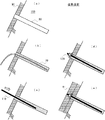
Landscapes
- Engineering & Computer Science (AREA)
- Mining & Mineral Resources (AREA)
- Pit Excavations, Shoring, Fill Or Stabilisation Of Slopes (AREA)
- Life Sciences & Earth Sciences (AREA)
- General Life Sciences & Earth Sciences (AREA)
- Paleontology (AREA)
- Civil Engineering (AREA)
- General Engineering & Computer Science (AREA)
- Structural Engineering (AREA)
Abstract
【課題】老朽化モルタル吹付の維持補修工法における鉄筋挿入工の品質向上及び機能向上並びに表面保護工(モルタル吹付工)の作業能率の向上を実現する。
【解決手段】老朽化モルタル吹付(90)の維持補修のために、老朽化モルタル吹付(90)及び地山(100)に形成した削孔(80)に挿入されグラウトにより固定される補強構造体(10A、10B、10C)であって、前記削孔の略全長に亘る長さを有する補強用の棒状体(11、17)と、前記棒状体(11、17)の軸方向における1又は複数の位置にて前記棒状体(11、17)を囲包して取り付けられかつ軸方向の先端側を向いた加圧面を形成可能である加圧手段(13、16)と、を備えたことを特徴とする。
【選択図】図2An object of the present invention is to improve the quality and function of a reinforcing bar insertion work and to improve the work efficiency of a surface protection work (mortar spraying work) in the maintenance repair method for aging mortar spraying.
SOLUTION: To maintain and repair an aging mortar spray (90), it is inserted into a hole (80) formed in an aging mortar spray (90) and a natural ground (100) and fixed by a grout. (10A, 10B, 10C), and a reinforcing rod-shaped body (11, 17) having a length over substantially the entire length of the hole, and one or more in the axial direction of the rod-shaped body (11, 17) Pressure means (13, 16) that surrounds and attaches the rod-shaped body (11, 17) at the position and is capable of forming a pressure surface facing the distal end side in the axial direction. Features.
[Selection] Figure 2
Description
本発明は、老朽化モルタル吹付の維持補修工法に用いる補強構造体及びその工法に関する。 The present invention relates to a reinforcing structure used in a maintenance repair method for aging mortar spraying and a method for the same.
従来、老朽化モルタル吹付の維持補修工事等において鉄筋挿入工及び表面保護工(モルタル吹付工)が用いられている。
図13は、従来の一般的な老朽化モルタル吹付の維持補修工法の各工程を示した地山の概略断面図である。(a)では、老朽化モルタル吹付90及び地山100に対して削孔80を形成する。(b)では、削孔80にグラウト70を注入する。この場合、例えば特許文献1に記載されたグラウンドアンカーのようにグラウト70を加圧注入することはなく、無加圧の状態でグラウトを注入する。(c)では、一般的には鉄筋である補強材110をグラウト内に挿入する。(d)では、補強材110の基端部をナット等の固定手段により固定する頭部処理を行う。図示しないが、補強材110を削孔の中心に位置させるためのスペーサを設ける。
Conventionally, reinforcing bar insertion work and surface protection work (mortar spraying work) are used in maintenance repair work for aging mortar spraying.
FIG. 13: is a schematic sectional drawing of the natural ground which showed each process of the maintenance repair method of the conventional general aging mortar spraying. In (a),
図示しない別の従来例では、図13(b)(c)に替えて、補強材110に注入ホースを取り付けてグラウトを注入する場合がある。
In another conventional example not shown, the grout may be injected by attaching an injection hose to the reinforcing
さらに補強材の固定後、図13(e)のように、表面保護工としてモルタル吹付工を行い、老朽化モルタル吹付90の上に新規モルタル吹付91を形成する。モルタル吹付工では、モルタルを吹き付けする前に鉄筋を配筋することがある。
Further, after fixing the reinforcing material, as shown in FIG. 13E, a mortar spraying work is performed as a surface protection work, and a
その他、老朽化モルタル吹付の維持補修工法の従来例として、特許文献2、3等がある。
In addition, there are
従来の老朽化モルタル吹付の維持補修のために行う鉄筋挿入工には、以下のような問題点がある。 There are the following problems in the rebar insertion work that is performed for the maintenance and repair of aging mortar spraying.
削孔に対し無加圧でグラウトを注入する場合、グラウトが完全に充填されていることを確認できない。また、無加圧であることから、加圧注入で造成されたグラウンドアンカーの周面摩擦抵抗の推定値を8割に低減して用いることが一般的となっている。よって、加圧すれば、周面摩擦抵抗を低減する必要がないことは明らかである。 When grout is injected into the hole without applying pressure, it cannot be confirmed that the grout is completely filled. In addition, since there is no pressure, it is common to use the estimated value of the peripheral frictional resistance of the ground anchor formed by pressure injection reduced to 80%. Therefore, it is clear that if the pressure is applied, it is not necessary to reduce the peripheral frictional resistance.
補強材に注入ホースを取り付けて削孔にグラウトを注入する場合は、削孔径が小さいために補強材が削孔の中心ではなく偏った位置に配置された状態でグラウトが硬化していた。一方、注入ホースを取り付けない場合も、従来のスペーサ(金属薄板等)を取り付けた補強材の搬入や挿入の際に、法面上のロープ足場という不安定な施工環境のために法面に接触することが多く、その結果、スペーサの位置がずれたり、スペーサが変形したりして、スペーサの機能を果たせず、補強材を削孔の中心に位置させることができなかった。そして、補強材が中心位置からずれた場合もそのまま施工せざるを得なかった。補強材が中心位置からずれると、補強材に必要なグラウトの被り厚が確保できなくなる結果、グラウトの中性化や地下水等により、補強材が腐食しやすくなるという問題点があった。 When the injection hose is attached to the reinforcing material and the grout is injected into the drilling hole, the grout is hardened in a state where the reinforcing material is arranged at a biased position instead of the center of the drilling hole because the hole diameter is small. On the other hand, even when the injection hose is not attached, when the reinforcing material with a conventional spacer (such as a thin metal plate) is carried in or inserted, it comes into contact with the slope due to an unstable construction environment such as a rope scaffolding on the slope. As a result, the position of the spacer is shifted or the spacer is deformed, so that the function of the spacer cannot be performed, and the reinforcing material cannot be positioned at the center of the hole. And even if the reinforcing material is deviated from the center position, it has to be applied as it is. If the reinforcing material deviates from the center position, it becomes impossible to secure the grout covering thickness necessary for the reinforcing material. As a result, there is a problem that the reinforcing material is easily corroded due to neutralization of the grout or groundwater.
また、表面保護工としてのモルタル吹付工において、モルタルを吹き付けする前に鉄筋を配筋する場合、不安定なロープ足場での作業のため、吹付面の凹凸に合わせて鉄筋を配筋させることに多くの時間を費やす。さらに、鉄筋を法面の凹凸に合わせて配筋することができない場合には、吹付量が増加するという問題点があった。 In addition, in the mortar spraying work as a surface protection work, when reinforcing the reinforcing bar before spraying the mortar, it is necessary to arrange the reinforcing bar according to the unevenness of the spraying surface for work on an unstable rope scaffold. Spend a lot of time. Furthermore, there is a problem that the amount of spraying increases when the reinforcing bars cannot be arranged according to the unevenness of the slope.
本発明は、老朽化モルタル吹付の維持補修工法における鉄筋挿入工において品質向上及び機能向上を実現すると共に、老朽化モルタル吹付の維持補修工法における表面保護工(モルタル吹付工)において作業能率の向上を実現することを目的とする。 The present invention realizes quality improvement and function improvement in reinforcing bar insertion work in the maintenance repair method for aging mortar spraying, and improves work efficiency in surface protection work (mortar spraying work) in the maintenance repair method for aging mortar spraying. It aims to be realized.
上記の目的を達成するために、本発明は、以下の構成を提供する。なお、括弧内の数字は、後述する図面中の符号であり、参考のために付する。 In order to achieve the above object, the present invention provides the following configuration. The numbers in parentheses are reference numerals in the drawings described later, and are attached for reference.
本発明による補強構造体は、老朽化モルタル吹付(90)の維持補修のために、老朽化モルタル吹付(90)及び地山(100)に形成した削孔(80)に挿入されグラウトにより固定される補強構造体(10A、10B、10C)であって、前記削孔の略全長に亘る長さを有する補強用の棒状体(11、17)と、前記棒状体(11、17)の軸方向における1又は複数の位置にて前記棒状体(11、17)を囲包して取り付けられかつ軸方向の先端側を向いた加圧面を形成可能である加圧手段(13、16)と、を備えている。 The reinforcing structure according to the present invention is inserted into the mortar spraying (90) and the drilling hole (80) formed in the ground (100) and fixed by grout for the maintenance repair of the aging mortar spraying (90). Reinforcing structure (10A, 10B, 10C), reinforcing rod-shaped body (11, 17) having a length over substantially the entire length of the hole, and axial direction of the rod-shaped body (11, 17) Pressure means (13, 16) attached to surround the rod-like body (11, 17) at one or a plurality of positions and capable of forming a pressure surface facing the distal end side in the axial direction; I have.
上記の補強構造体における第1の態様は、前記棒状体は中実棒状体(11)であり、前記中実棒状体(11)との間に所定の間隙(d2)を空けて同軸に配置されかつ前記加圧手段よりも基端側に延在する管状体(12)をさらに備え、前記加圧手段は、前記管状体(12)の先端面(12b)に固定されかつ前記先端面(12b)よりも大径である環状の加圧板(13)であることを特徴とする。 In the first aspect of the reinforcing structure, the rod-shaped body is a solid rod-shaped body (11), and is coaxially disposed with a predetermined gap (d2) between the solid rod-shaped body (11). And a tubular body (12) extending to the proximal end side with respect to the pressurizing means, the pressurizing means being fixed to the distal end surface (12b) of the tubular body (12) and the distal end surface ( It is an annular pressure plate (13) having a larger diameter than 12b).
上記の補強構造体における第2の態様は、前記棒状体は中空棒状体(17)であり、前記中空棒状体(17)との間に所定の間隙(d2)を空けて同軸に配置されかつ前記加圧手段よりも基端側に延在する管状体(12)をさらに備え、前記加圧手段は、前記管状体(12)の先端面(12b)に固定されかつ前記先端面(12b)よりも大径である環状平板の加圧板(13)であることを特徴とする。 In the second aspect of the reinforcing structure, the rod-shaped body is a hollow rod-shaped body (17), and is disposed coaxially with a predetermined gap (d2) between the hollow rod-shaped body (17) and It further includes a tubular body (12) extending to the proximal end side with respect to the pressurizing means, and the pressurizing means is fixed to the distal end surface (12b) of the tubular body (12) and the distal end surface (12b) The pressure plate (13) is an annular flat plate having a larger diameter than that of the pressure plate.
上記の補強構造体における第1及び第2の態様において、前記管状体(12)の管壁に複数の孔(12a)を設けたことが、好適である。また、前記加圧板(13)の外周縁(13b)から径方向外側に突出する複数の弾性スペーサー(13d)を有することが、好適である。 In the first and second aspects of the above reinforcing structure, it is preferable that a plurality of holes (12a) are provided in the tube wall of the tubular body (12). In addition, it is preferable to have a plurality of elastic spacers (13d) projecting radially outward from the outer peripheral edge (13b) of the pressure plate (13).
上記の補強構造体における第3の態様は、前記棒状体は中実棒状体(11)であり、前記加圧手段は、第1の加圧板部材(16a)と第2の加圧板部材(16b)とを軸方向に重畳した加圧板スペーサー(16)であり、前記第1の加圧板部材(16a)は、前記中実棒状体(11)に固定され、第1の環状部(16a1)と該第1の環状部から径方向外側に突出する複数の第1のスペーサー突起(16a2)とを有し、前記第2の加圧板部材(16b)は、前記中実棒状体(11)の軸周りに回動可能であり、第2の環状部(16b1)と該第2の環状部から径方向外側に突出する複数の第2のスペーサー突起(16b2)と該第2のスペーサー突起(16b2)から軸方向に突出する脚部(16b3)とを有し、かつ、前記加圧板スペーサー(16)は、前記第1の加圧板部材(16a)に対して前記第2の加圧板部材(16b)が回動することにより、軸方向から視て、前記第1と第2のスペーサー突起(16a2,16b2)同士が互いに重なった非加圧形態と、前記第1と第2のスペーサー突起(16a2,16b2)同士が互いにずれて前記加圧面を形成した加圧形態との間で移行可能であることを特徴とする。 In the third aspect of the reinforcing structure, the rod-shaped body is a solid rod-shaped body (11), and the pressurizing means includes a first pressure plate member (16a) and a second pressure plate member (16b). ) In the axial direction, and the first pressure plate member (16a) is fixed to the solid rod-like body (11), and the first annular portion (16a1) A plurality of first spacer protrusions (16a2) projecting radially outward from the first annular portion, and the second pressure plate member (16b) is an axis of the solid rod-like body (11) A second annular portion (16b1), a plurality of second spacer projections (16b2) projecting radially outward from the second annular portion, and the second spacer projections (16b2) Leg portion (16b3) protruding in the axial direction from the first pressure plate member (16a) with respect to the first pressure plate member (16a). When the member (16b) rotates, the first and second spacer protrusions (16a2, 16b2) overlap each other when viewed from the axial direction, and the first and second spacers The protrusions (16a2, 16b2) are shifted from each other, and can be shifted between the pressing forms in which the pressing surfaces are formed.
本発明による老朽化モルタル吹付の維持補修工法は、上記の補強構造体(10A、10B、10C)を用いた工法であって、老朽化モルタル吹付(90)及び地山(100)に削孔(80)を形成する工程と、前記削孔(80)の全体にグラウト(70)を注入した後に該削孔(80)に前記補強構造体(10A、10C)を挿入していくことにより、又は、前記削孔(80)に前記補強構造体(10B)の全体を挿入した後に該削孔(80)にグラウト(70)を注入していくことにより、前記加圧手段に形成された前記加圧面が該加圧面よりも先端側のグラウト(70)を加圧する工程と、を有する。 The maintenance repair method for aging mortar spraying according to the present invention is a construction method using the above-mentioned reinforcing structure (10A, 10B, 10C), in which mortar spraying (90) and ground (100) are drilled ( 80) and by inserting the reinforcing structure (10A, 10C) into the hole (80) after injecting the grout (70) into the entire hole (80), or The grout (70) is injected into the hole (80) after the entire reinforcing structure (10B) is inserted into the hole (80), whereby the pressurizing means formed in the pressurizing means is formed. And the pressure surface pressurizes the grout (70) on the tip side of the pressure surface.
上記の老朽化モルタル吹付の維持補修工法の第1の態様は、上記補強構造体の第1の態様を用いており、老朽化モルタル吹付(90)及び地山(100)に削孔(80)を形成する工程と、前記削孔(80)の全体にグラウト(70)を注入する工程と、前記補強構造体(10A)を前記削孔(80)に挿入していくことにより、前記加圧板(13)が該加圧板(13)よりも先端側のグラウト(70)を加圧する工程と、を有する。 The first aspect of the maintenance and repair method of the above-mentioned aging mortar spraying uses the first aspect of the above-mentioned reinforcing structure, and drilling holes (80) in the aging mortar spraying (90) and ground (100) A step of injecting a grout (70) into the whole of the hole (80), and inserting the reinforcing structure (10A) into the hole (80), whereby the pressure plate (13) has a step of pressurizing the grout (70) on the tip side of the pressure plate (13).
上記の老朽化モルタル吹付の維持補修工法の第1の態様において、前記補強構造体(10A)を前記削孔(80)に挿入する途中、前記加圧板(13)が前記削孔の入口を通過した直後に挿入を一時停止し、前記中実棒状体(11)と前記管状体(12)の間の間隙(d2)にグラウト(70)を注入し、その後、挿入を再開することが好適である。また、前記補強構造体(10A)を前記削孔(80)に挿入していく際、前記削孔(80)から排出されるグラウト(70)の量及び挿入速度のうち少なくとも一方を調整することにより、前記削孔(80)の内部圧力を制御することが好適である。さらにまた、前記補強構造体(10A)の挿入を完了した後、前記削孔(80)に二次グラウトを注入することが好適である。 In the first aspect of the maintenance and repair method for aging mortar spraying, the pressure plate (13) passes through the entrance of the drilling hole while the reinforcing structure (10A) is inserted into the drilling hole (80). Immediately after the insertion, it is preferable to pause the insertion, inject the grout (70) into the gap (d2) between the solid rod-like body (11) and the tubular body (12), and then resume the insertion. is there. Further, when the reinforcing structure (10A) is inserted into the hole (80), at least one of the amount of grout (70) discharged from the hole (80) and the insertion speed is adjusted. Thus, it is preferable to control the internal pressure of the drilling hole (80). Furthermore, it is preferable to inject a secondary grout into the drilling hole (80) after the insertion of the reinforcing structure (10A) is completed.
上記の老朽化モルタル吹付の維持補修工法の第2の態様は、上記補強構造体(10B)の第2の態様を用いており、老朽化モルタル吹付(90)及び地山(100)に削孔(80)を形成する工程と、前記削孔(80)に前記補強構造体(10B)の全体を挿入する工程と、前記補強構造体(10B)の前記中空棒状体(17)の中空を通してグラウト(70)を前記削孔(80)に注入していくことにより、前記加圧板(13)が該加圧板(13)よりも先端側のグラウト(70)を加圧する工程と、を有する。 The second aspect of the maintenance and repair method for the aging mortar spraying uses the second aspect of the reinforcing structure (10B), and drills holes in the aging mortar spraying (90) and ground (100). A step of forming (80), a step of inserting the entire reinforcing structure (10B) into the drilling hole (80), and a grout through the hollow of the hollow rod-like body (17) of the reinforcing structure (10B). The pressure plate (13) pressurizes the grout (70) on the tip side of the pressure plate (13) by injecting (70) into the hole (80).
上記の老朽化モルタル吹付の維持補修工法の第2の態様において、前記中空棒状体(17)の中空を通してグラウト(70)を前記削孔(80)に注入していく際、前記中空棒状体(17)の中空に注入するグラウト(70)の量を調整することにより前記削孔(80)の内部圧力を制御することが好適である。 In the second aspect of the maintenance and repair method for aging mortar spraying, when the grout (70) is injected into the hole (80) through the hollow of the hollow rod (17), the hollow rod ( It is preferable to control the internal pressure of the drilling hole (80) by adjusting the amount of grout (70) injected into the hollow of 17).
上記の老朽化モルタル吹付の維持補修工法の第3の態様は、上記補強構造体(10C)の第3の態様を用いており、老朽化モルタル吹付(90)及び地山(100)に削孔(80)を形成する工程と、前記削孔(80)の全体にグラウト(70)を注入する工程と、前記補強構造体(10C)の前記加圧板スペーサー(16)を前記非加圧形態として前記削孔(80)への挿入を開始し、挿入しつつ前記中実棒状体(11)を軸周りに回動させることにより前記加圧板スペーサー(16)を前記加圧形態へと移行させる工程と、前記補強構造体(10C)を前記削孔(80)にさらに挿入していくことにより、前記加圧形態となった前記加圧板スペーサー(16)が該加圧板スペーサーよりも先端側のグラウト(70)を加圧する工程と、を有する。 The third aspect of the maintenance and repair method for aging mortar spraying uses the third aspect of the reinforcing structure (10C), and drills holes in the aging mortar spraying (90) and ground (100). Forming the step (80), injecting the grout (70) into the entire hole (80), and the pressure plate spacer (16) of the reinforcing structure (10C) as the non-pressurized form. The step of starting the insertion into the drilling hole (80) and moving the pressure plate spacer (16) to the pressure form by rotating the solid rod-like body (11) around the axis while inserting. And by further inserting the reinforcing structure (10C) into the drilling hole (80), the pressure plate spacer (16) in the pressurization form is grouting on the tip side of the pressure plate spacer. Pressurizing (70).
上記いずれかの老朽化モルタル吹付の維持補修工法において、前記削孔(80)へのグラウト(70)の注入及び前記削孔(80)への前記補強構造体(10A、10B、10C)の挿入の双方を完了した後、前記補強構造体(10A、10B、10C)の基端部に十字状の連結鉄筋(20)を取り付けた後に前記補強構造体(10A、10B、10C)の基端部を固定する工程と、老朽化モルタル吹付(90)の上にモルタルを吹き付けることにより新規モルタル吹付(91)を形成する工程と、を有することが、好適である。 In any one of the above maintenance and repair methods for spraying aging mortar, the grout (70) is injected into the hole (80) and the reinforcing structure (10A, 10B, 10C) is inserted into the hole (80). After completing both, after attaching a cross-shaped connecting reinforcing bar (20) to the base end of the reinforcing structure (10A, 10B, 10C), the base end of the reinforcing structure (10A, 10B, 10C) It is preferable to have a step of fixing the mortar and a step of forming a new mortar spray (91) by spraying the mortar on the aged mortar spray (90).
本発明による老朽化モルタル吹付の維持補修工法において用いる連結鉄筋(20)は、2つの長尺の鉄筋要素を備え、前記2つの鉄筋要素は、各々の長手方向中央部にて直交するように重ね合わされており、前記2つの鉄筋要素の各々は、平行に配置された偶数本の鉄筋を少なくとも具備しかつ該偶数本の鉄筋の両端部は中央部に対して折り曲げられている。 The connecting reinforcing bar (20) used in the maintenance repair method for aging mortar spray according to the present invention includes two long reinforcing bar elements, and the two reinforcing bar elements are superposed so as to be orthogonal to each other in the longitudinal center portion. Each of the two reinforcing bar elements includes at least an even number of reinforcing bars arranged in parallel, and both ends of the even number of reinforcing bars are bent with respect to the central portion.
本発明による老朽化モルタル吹付の維持補修工法に用いる補強構造体は、補強用の棒状体の周囲に1又は複数の加圧手段を設けている。このような補強構造体を用いて老朽化モルタル吹付の維持補修工法を行う場合、加圧手段よりも先端側に位置するグラウトを加圧状態とすることができる。 The reinforcing structure used in the maintenance repair method for aging mortar spray according to the present invention is provided with one or a plurality of pressurizing means around a reinforcing rod-shaped body. When the maintenance repair method for aging mortar spraying is performed using such a reinforcing structure, the grout positioned on the tip side of the pressurizing means can be in a pressurized state.
また、削孔から排出されるグラウトの量若しくは削孔に注入するグラウトの量を調整することにより、又は、削孔に挿入する補強構造体の挿入速度を調整することにより、削孔の内部圧力を制御する。この結果、従来に比べて強度に優れた補強構造が得られるとともに、削孔内及び周辺の空洞や亀裂に確実にグラウトが充填される。 Also, by adjusting the amount of grout discharged from the hole or the amount of grout injected into the hole, or by adjusting the insertion speed of the reinforcing structure to be inserted into the hole, the internal pressure of the hole is adjusted. To control. As a result, a reinforcing structure superior in strength compared to the conventional one can be obtained, and the grout can be surely filled in the cavity and the crack in and around the hole.
補強構造体の挿入完了後、補強構造体の基端部に十字状の連結鉄筋を取り付けた後に補強構造体の基端部を固定し、その上に新規のモルタルを吹き付けることにより、新規モルタル吹付と老朽化モルタル吹付とを一体化するとともに、鉄筋挿入工に発生する引張力を地山に伝達する法面工の役割を発揮する。また、従来の、鉄筋を法面の凹凸に合わせて配筋する作業が不要となる。 After inserting the reinforcing structure, attach a cross-shaped connecting bar to the base end of the reinforcing structure, fix the base end of the reinforcing structure, and spray new mortar on it to spray new mortar. As well as integrating aging mortar spraying, it exerts the role of slope work to transmit the tensile force generated in the rebar insertion work to the ground. In addition, the conventional work of arranging reinforcing bars in accordance with the unevenness of the slope becomes unnecessary.
以下、実施例を示した図面を参照しつつ、本発明の実施形態を説明する。なお、図面中では、各実施例に共通する構成要素については、同じ符号を付している。
本発明による老朽化モルタル吹付の維持補修工法は、補強構造体を地山に挿入しグラウトにより固定する補強構造体挿入工と、補強構造体挿入工の後に老朽化モルタル吹付の表面にモルタル吹付を行う表面保護工とから構成されている。本発明による補強構造体は、従来の補強材に替えて用いるものであり、これを用いた工法は、従来とは異なる工程を含むものとなる。
Hereinafter, embodiments of the present invention will be described with reference to the drawings showing examples. In the drawings, components common to the respective embodiments are denoted by the same reference numerals.
The maintenance and repair method for aging mortar spraying according to the present invention includes a reinforcing structure insertion work in which a reinforcing structure is inserted into a natural ground and fixed by a grout, and a mortar spraying is applied to the surface of an aging mortar spraying after the reinforcing structure insertion work. It consists of surface protection work to be done. The reinforcing structure according to the present invention is used in place of the conventional reinforcing material, and the construction method using the reinforcing structure includes steps different from the conventional one.
(1)補強構造体の第1の実施例及びその工法
図1は、本発明による第1の実施例の補強構造体10Aを適用して施工した老朽化モルタル吹付の維持補修工法の概略断面図である。地山100の表面101には、老朽化モルタル吹付90が付設されている。本工法を施工する前の老朽化モルタル吹付90は、それ自体に亀裂等が生じるとともに地山100への付着性も低下している。また、背面側が侵食されて空洞102が生じている場合もある。
(1) First embodiment of reinforcing structure and its construction method FIG. 1 is a schematic cross-sectional view of a maintenance repair method for aging mortar spraying applied by applying the reinforcing
補強構造体10Aは、地山100に形成された削孔80に充填されたグラウト70の中心に挿入されている。以下、補強構造体10Aについて、挿入されたときに削孔80の孔底側となる側を軸方向における「先端側」と称し、反対側を「基端側」と称し、基端側の近傍を「基端部」と称する(後述する他の実施例についても同様)。補強構造体10Aの基端部は、老朽化モルタル吹付90の表面上で固定され、これを被覆するように新規モルタル吹付91が形成されている。
The reinforcing structure 10 </ b> A is inserted into the center of the
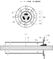
図2(a)は、図1の工法において、補強構造体10Aを削孔80に挿入する工程を、図2(b)は二次グラウトを注入する工程を示した部分断面図である(黒矢印はグラウトの方向を示す)。図2(a)の工程の前に、削孔80の形成とグラウト70(一次グラウト)の注入は完了している。図3(a)は、図2のA−A断面図であり、図3(b)は、補強構造体10Aの概略的な側断面図である。これらの図面を参照して、補強構造体10Aについて説明する。
2A is a partial cross-sectional view showing a step of inserting the reinforcing
補強構造体10Aは、補強用の中実棒状体11を備えている。中実棒状体11は、削孔80の略全長に挿入可能な長さを有している。中実棒状体11の先端は、削孔80の孔底近傍に位置する。中実棒状体11は、例えば、鉄筋である。
The reinforcing
中実棒状体11の軸方向における所定の中間位置において、中実棒状体11を囲包するように環状平板の加圧板13が取り付けられている。図3に示すように、加圧板13は、円形の内周縁13aと外周縁13bを有する。中実棒状体11の周囲への加圧板13の取付けにおいては、中実棒状体11と加圧板13の内周縁13aとの間に所定の間隙d1が存在する。加圧板13は、削孔80内のグラウト70を加圧するための加圧手段である。加圧板13における先端側を向いた面13cが、グラウト70を押圧する加圧面となる。加圧板13の材質は、好適には鋼製であるが、プラスチック製や鉄製でもよい。
At a predetermined intermediate position in the axial direction of the
さらに補強構造体10Aは、加圧板13よりも基端側に延在する管状体12を備えている。管状体12は、中実棒状体11との間に所定の間隙d2を空けて同軸に配置されている。管状体12の材質は、好適には鋼製であるが、プラスチック製や鉄製でもよい。図3(b)に示すように、管状体12の管壁には、複数の孔12aが設けられている。孔12aの位置は、加圧板13の近傍が好適である(後述する図6(d)の工程に関連)。この孔12aを通して管状体12の内部と周辺部の間でグラウトが通過可能である。
Furthermore, the reinforcing structure 10 </ b> A includes a
以下では、中実棒状体11として鉄筋を、管状体12として鋼管を用いた場合を例として説明する。
加圧板13は、鋼管12の先端面12bに当接するように適宜の固定手段により固定されている。図示の例では、固定手段が3つのくさび形の固定治具14であり、図3に示すように加圧板13の内周縁13aと鉄筋11の間に等角度間隔で打ち込まれている。これにより、鉄筋11と鋼管12と加圧板13とが一体化され、補強構造体10Aを形成する。なお、隣り合う固定治具14同士の間では、間隙d1が確保されている。これらの間隙d1を通して鋼管12の外部と内部の間でグラウトが通過可能である。
Hereinafter, a case where a reinforcing bar is used as the solid rod-
The
図3(a)(b)に示すように、加圧板13は、鋼管12の先端面12bよりも大径であり、外周縁13bは径方向外側に突出した位置にある。図3(a)に示すように、補強構造体10Aが削孔80の中心に挿入されると、加圧板13の外周縁13bと削孔80の内壁との間には所定の間隙d3が存在する。この間隙d3もグラウトが通過可能である。
As shown in FIGS. 3 (a) and 3 (b), the
補強構造体10Aを所定の速度で挿入していくと、加圧板13よりも先端側のグラウトが、間隙d3を通って加圧板13よりも基端側へと相対的に移動する。同時に、加圧板13よりも先端側のグラウトは、鋼管12の先端の間隙d1から鋼管12の内部(間隙d2)に入り込んで鋼管12内を充填し、余分なグラウトは削孔80から排出される。
When the reinforcing
補強構造体10Aを十分な低速度で挿入した場合、削孔80から排出されるグラウトの容量は、補強構造体10Aにおける削孔80内に挿入された部分の体積と一致するはずである。しかし、実際にはグラウトに粘性があるため、一定速度以上で補強構造体10Aを挿入すると抵抗が発生する。この挿入抵抗は、加圧板13があることによってさらに大きくなる。挿入抵抗に抗して補強構造体10Aを強制的に挿入することにより、加圧板13よりも先端側のグラウトが加圧状態となる。この圧力は、人力施工の場合にはさほど大きくないが、機械施工の場合は、大きな圧力が得られる。
When the reinforcing
図2(a)に示すように、補強構造体10Aの基端部には、調整装置60が取り付けられている。取付けは、補強構造体10Aの挿入開始前に行う。調整装置60は、グラウトの排出及び注入を行うことができる排出注入治具61及びこれに接続された排出注入ホース64を具備し、排出注入ホース64の途中には圧力計62及び開閉バルブ63が取り付けられている。排出注入治具61には、排気注入治具61内の空気を排出させるための排気バルブ66が取り付けられている。排出注入治具61は、鋼管12の基端側開口に接続される。図示しないが、調整装置60は、流量計及び挿入抵抗計測器を含んでもよい。圧力計62等の計測器のデータは手動又は自動で監視され、開閉バルブ63等の制御器は手動又は自動で制御される。調整装置60は、グラウトの排出及び注入のいずれにも用いることができるが、補強構造体10Aの挿入工程においては、グラウト排出のために用いられる。
As shown in FIG. 2A, an
挿入工程においては、圧力計62により内部圧力を監視しつつ、鋼管12の内部を通って排出されるグラウト量を開閉バルブ63により調整することにより、内部圧力を制御することができる。排出量を減少させると内部圧力が上昇する。排出量を増大させると内部圧力が低下する。排出されるグラウトの圧力は、内部圧力と同じである。通常は、内部圧力が一定となるように開閉バルブ63を調整して挿入を行う。開閉バルブ63を閉じて挿入を続けると、内部圧力は上昇し、加圧状態が保持される。
In the insertion step, the internal pressure can be controlled by adjusting the grouting amount discharged through the inside of the
また、挿入工程においては、挿入抵抗を監視しつつ、挿入速度を調整することにより、内部圧力を制御することができる。挿入速度を速めると挿入抵抗が大きくなり内部圧力が上昇する。挿入速度を遅くすると挿入抵抗が小さくなり内部圧力が低下する。 In the insertion process, the internal pressure can be controlled by adjusting the insertion speed while monitoring the insertion resistance. Increasing the insertion speed increases the insertion resistance and increases the internal pressure. If the insertion speed is slowed, the insertion resistance decreases and the internal pressure decreases.
さらに、挿入工程においては、内部圧力及び挿入抵抗の変化を監視することにより、加圧板13が通過している位置における地山の亀裂の状況を推定できる。例えば、削孔の内壁に亀裂がありグラウトが逸出しているとき、その位置を加圧板13が通過すると逸失量が変化する。その結果、挿入抵抗及び内部圧力が変化する。これに応じて、その位置で挿入を一時停止してグラウトを供給することにより、亀裂に対して十分なグラウトを充填することができる。このように、亀裂の有無が推定可能となり、個別の注入の精度を変更することができ、亀裂情報にあった注入量や注入圧を設定できる。
Furthermore, in the insertion process, it is possible to estimate the state of cracks in the natural ground at the position where the
図2(b)に示すように、補強構造体10Aの挿入完了後、二次グラウト注入を行う。このときの調整装置60は、グラウト注入のために用いられる。また、排出注入治具61と削孔80の開口の間に止水治具65を設置し、削孔80からグラウトが排出されることを防ぐ。この場合は、調整装置60により、削孔80に対して注入されるグラウトの量を調整できる。二次グラウトが鋼管12の内部に注入されると、鋼管12の管壁の孔12a及び先端面の間隙d1を通って鋼管12の周辺部及び先端部に供給され、これらの箇所において適切な加圧状態を得ることができる。また、鋼管12の周辺部に供給されたグラウトは、吹付背面の空洞102や表層地山にも加圧状態で注入される。空洞102への注入状況も内部圧力の変化により確認できる。
As shown in FIG. 2B, after the insertion of the reinforcing
空洞102へのグラウト注入が完了し、グラウトが硬化すると、グラウトで満たされた鋼管12内に鉄筋11が存在する補強構造となるので、従来の鉄筋挿入工よりも剛な構造となる。これにより、鉄筋11に発生する変位が抑制される。また、グラウトを拘束しているので、地山100の動きによるグラウトにおけるクラックの発生も抑制される。さらに、削孔80内の径方向外側から内側にかけて、グラウト、鋼管12、グラウト、鉄筋11の順で構成されていることにより、削孔80の内壁に面しているグラウトにクラックが発生した場合には、クラックが鋼管12により遮られ、内側の鉄筋11に達することがない。また、鋼管12による遮蔽により、鉄筋11に対する高い防錆効果が期待できる。
When the grout injection into the
また、施工後に吹付背面の空洞化や吹付背面の地山の風化が進行し、老朽化したモルタル吹付や風化層が不安定となり、鉄筋11にせん断力が作用した場合にも、本発明の補強構造体による補強構造は、従来より剛な構造であるので、変形を抑制することができる。よって、モルタル吹付に発生する亀裂幅の拡大防止等の効果が得られ、雨水の浸透等による地山劣化の進行が阻止できる。
Further, after the construction, the hollowing of the back of the spraying and the weathering of the ground on the back of the spraying progress, the mortar spraying and weathering layer that has deteriorated become unstable, and the reinforcing force of the present invention is also applied when the shearing force acts on the reinforcing
図4(a)(b)は、補強構造体10Aの変形例を示す、図3(a)(b)と同様の図である。この変形例では、加圧板13の外周縁13b上の複数の位置からそれぞれ径方向外側に突出する弾性スペーサー13dを設けている。弾性スペーサー13dは、加圧板13に固定されることで、軸方向の位置ずれを生じない。複数の弾性スペーサー13dは、円環形状の加圧板13の外周縁13b上に等角度間隔で配置されている。複数の弾性スペーサー13dの径方向長さは同じであり、補強構造体10を削孔80の中心に位置させるためのスペーサーの役割を果たす。すなわち、補強構造体10が削孔80の中心に位置したとき、弾性スペーサー13dの先端が削孔80の内壁にほぼ達する程度の長さとする。弾性スペーサー13dの材質は、例えばゴムである。弾性材であるので、搬入時や挿入時には適宜変形することにより作業の妨げとならず、挿入後は本来の形状に復帰してスペーサとして機能する。弾性材であっても、スペーサーとしての役割を果たす程度の硬さは備えている。
FIGS. 4A and 4B are views similar to FIGS. 3A and 3B, showing a modification of the reinforcing
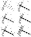
図5(a)〜(f)は、補強構造体10Aを用いた老朽化モルタル吹付の維持補修工法の一実施例の各工程を示した地山の概略断面図である。
(a)では、老朽化モルタル吹付90及び地山100に対して削孔80を形成する。
(b)では、孔底まで注入パイプを挿入し、孔底から削孔80の全体にグラウト70を注入する。この時点では、グラウトは無加圧の状態である。
(c)では、加圧板13を備えた補強構造体10Aに排出注入治具61を取付け、削孔80内に挿入していく。排出注入治具61は、グラウト排出のために用いる。上述した通り、グラウト排出量及び挿入速度のうちいずれか一方又は双方を調整することにより内部圧力を制御する。こうして、補強構造体10Aの挿入を完了する。
(d)では、二次グラウトを注入する。このとき、二次グラウト注入のために排出注入治具61及び止水治具65を用いる。
(e)では、補強構造体10Aの基端部の頭部処理を行う。好適には、連結鉄筋20を用いた方法により行う(図12において説明する)。
(f)では、表面保護工としてモルタル吹付工を行い、老朽化モルタル吹付90の上に新規モルタル吹付91を形成する。
FIGS. 5A to 5F are schematic cross-sectional views of a natural ground showing respective steps of an embodiment of a maintenance repair method for aging mortar spraying using a reinforcing
In (a), drilling holes 80 are formed in the aging
In (b), an injection pipe is inserted to the bottom of the hole, and the
In (c), the
In (d), a secondary grout is injected. At this time, the
In (e), the head processing of the base end part of 10 A of reinforcement structures is performed. Preferably, this is performed by a method using the connecting reinforcing bars 20 (described in FIG. 12).
In (f), a mortar spraying work is performed as a surface protection work, and a new mortar spraying 91 is formed on the aging mortar spraying 90.
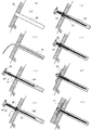
図6(a)〜(h)は、補強構造体10Aを用いた老朽化モルタル吹付の維持補修工法の別の実施例の各工程を示した地山の概略断面図である。
(a)では、老朽化モルタル吹付90及び地山100に対して削孔80を形成する。
(b)では、孔底まで注入パイプを挿入し、孔底から削孔80の全体にグラウト70を注入する。この時点では、グラウトは無加圧の状態である。
(c)では、加圧板13を備えた補強構造体10Aの削孔80への挿入を開始する。そして、加圧板13が削孔80の入口を通過した直後に挿入を一時停止する。
(d)では、補強構造体10Aを停止させた状態にて、排出注入治具61及び止水治具65を取付け、鋼管12内(図3の間隙d2)にグラウトを注入し、充填する。このとき、鋼管12の孔12aは、止水治具65により閉鎖されるようにする。この工程を付加することにより、上述の図5の工法に比べて鋼管12内へのグラウトの充填に時間が掛からず迅速な施工が可能となる。
(e)鋼管12内へのグラウト注入完了後に、補強構造体10Aの挿入を再開し、加圧板13をグラウト内に挿入していく。このときは、排出注入治具61をグラウト排出のために用いる。グラウト排出量及び挿入速度のうちいずれか一方又は双方を調整することにより内部圧力を制御する。
(f)では、二次グラウトを注入する。このとき、二次グラウト注入のために排出注入治具61及び止水治具65を用いる。
(g)では、補強構造体10Aの基端部の頭部処理を行う。好適には、連結鉄筋20を用いた方法により行う(図12において説明する)。
(h)では、表面保護工としてモルタル吹付工を行い、老朽化モルタル吹付90の上に新規モルタル吹付91を形成する。
FIGS. 6A to 6H are schematic cross-sectional views of natural ground showing each step of another embodiment of the maintenance repair method for aging mortar spraying using the reinforcing
In (a), drilling holes 80 are formed in the aging
In (b), an injection pipe is inserted to the bottom of the hole, and the
In (c), insertion of the reinforcing structure 10 </ b> A provided with the
In (d), with the reinforcing
(E) After the grout injection into the
In (f), a secondary grout is injected. At this time, the
In (g), the head processing of the base end portion of the reinforcing
In (h), a mortar spraying work is performed as a surface protection work, and a new mortar spraying 91 is formed on the aging mortar spraying 90.
(2)補強構造体の第2の実施例及びその工法
図7(a)は、本発明による第2の実施例の補強構造体10Bを適用した老朽化モルタル吹付の維持補修工法におけるグラウト(一次グラウト)注入工程を示した概略断面図である(黒矢印はグラウトの方向を示す)。図7(b)は二次グラウトを注入する工程を示した概略断面図である。図7(a)の工程の前に、削孔80の形成が完了している。これらの図面を参照して、補強構造体10Bについて説明する。
(2) Second embodiment of reinforcing structure and its construction method FIG. 7 (a) is a grout (primary) in the maintenance repair method for aging mortar spraying using the reinforcing
補強構造体10Bは、補強用の中空棒状体17を備える。中空棒状体17は、先端側及び基端側が開口しており、例えば、中空ボルトである。中空棒状体17の先端側の開口17aは、削孔80の孔底近傍に位置する。補強構造体10Bと上述の第1の実施例の補強構造体10Aとは、棒状体が中空か中実かという点において構造的に相違している。
The reinforcing
中空棒状体17の軸方向における所定の中間位置において、環状平板の加圧板13が取り付けられている。さらに、加圧板13よりも基端側に延在する管状体12を備えている。管状体12の管壁には、複数の孔12aが設けられている。加圧板13及び管状体12の構造については、上述の第1の実施例の補強構造体10Aと同様である。
At a predetermined intermediate position in the axial direction of the
以下では、中空棒状体17として中空ボルトを、管状体12として鋼管を用いた場合を例として説明する。
第2の実施例では、削孔80を形成した後、グラウトを注入しない状態で先ず中空ボルト17の全体を削孔80に挿入する。図7(a)は、それに続くグラウト注入工程を示している。
Hereinafter, a case where a hollow bolt is used as the hollow rod-
In the second embodiment, after the
図7(a)に示すように、補強構造体10Bの基端部には、調整装置60’が取り付けられている。調整装置60’は、注入治具61’及びこれに接続された排出注入ホース64を具備し、排出注入ホース64の途中には圧力計62及び開閉バルブ63が取り付けられている。注入治具61’は、中空ボルト17の基端側開口に接続されるため、中空ボルト17に適合する径を有する。図示しないが、調整装置60’は、流量計を含んでもよい。圧力計62等の計測器のデータは手動又は自動で監視され、開閉バルブ63等の制御器は手動又は自動で制御される。調整装置60’は、中空ボルト17の挿入完了後の注入工程において、グラウト注入のために用いられる。
As shown in FIG. 7A, an adjustment device 60 'is attached to the base end portion of the reinforcing
中空ボルト17の内部にグラウトを注入していくと、中空ボルト17の先端側の開口17aから削孔80内に放出され、削孔80の孔底側からグラウト70が充填されていく。グラウト70が加圧板13に到達すると、加圧板13により流動抵抗が大きくなるため加圧板13よりも先端側のグラウトが加圧状態となる。注入するグラウトの量を調整することにより、この先端側の内部圧力を制御することができる。注入量を増大させると内部圧力は上昇する。注入量を減少させると内部圧力は低下する。
When the grout is injected into the
さらに注入を続けると、グラウト70は、加圧板13を超えて鋼管12と削孔80の内壁との間の間隙を充填し、同時に、鋼管12の内部にも入り込んで鋼管12内を充填し、余分なグラウトは削孔80から排出される。
If the injection is further continued, the
図7(a)のグラウト注入工程の完了後、図7(b)に示すように、二次グラウトの注入を行う。このとき用いる排出注入治具61は、注入治具61’より大径であり、鋼管12の基端側開口に接続される。また、排出注入治具61と削孔80の開口の間に止水治具65を設置し、削孔80からグラウトが排出されることを防ぐ。二次グラウトが鋼管12の内部に注入されると、鋼管12の管壁の孔12a及び先端面の間隙を通って鋼管12の周辺部及び先端部に供給され、これらの箇所において十分な加圧状態を得ることができる。また、二次グラウトは中空ボルト17を通って削孔80の孔底にも供給されるため、先端部分においても十分な加圧状態を得られる。さらに、吹付背面の空洞102や表層地山にも加圧状態でグラウトが注入される。
After the completion of the grout injection step in FIG. 7A, secondary grout is injected as shown in FIG. 7B. The
図8(a)〜(f)は、補強構造体10Bを用いた老朽化モルタル吹付の維持補修工法の各工程を示した地山の概略断面図である。
(a)では、老朽化モルタル吹付90及び地山100に対して削孔80を形成する。
(b)では、削孔80に、加圧板13を備えた補強構造体10Bの全体を挿入する。
(c)では、中空ボルト17を通して削孔80にグラウトを注入する。このとき、グラウト注入のために注入治具61’を用いる。上述した通り、グラウト注入量を調整することにより内部圧力を制御する。
(d)では、二次グラウトを注入する。このとき、二次グラウト注入のために排出注入治具61及び止水治具65を用いる。
(e)では、補強構造体10Bの基端部の頭部処理を行う。好適には、連結鉄筋20を用いた方法により行う(図12において説明する)。
(f)では、表面保護工としてモルタル吹付工を行い、老朽化モルタル吹付90の上に新規モルタル吹付91を形成する。
8 (a) to 8 (f) are schematic cross-sectional views of a natural ground showing each process of the maintenance repair method for aging mortar spraying using the reinforcing
In (a), drilling holes 80 are formed in the aging
In (b), the entire reinforcing structure 10 </ b> B including the
In (c), grout is injected into the
In (d), a secondary grout is injected. At this time, the
In (e), the head part process of the base end part of the
In (f), a mortar spraying work is performed as a surface protection work, and a new mortar spraying 91 is formed on the aging mortar spraying 90.
(3)補強構造体の第3の実施例及びその工法
図9は、本発明による第3の実施例の補強構造体10Cを適用して行った老朽化モルタル吹付の維持補修工法の概略断面図である。図10(a)は、図9の補強構造体10Cの備える加圧板スペーサー16の斜視図、(b)は(a)のB−B断面図、(c)は断面展開図、(d)は加圧板スペーサー16の取付状態の断面図である。
これらの図面を参照して、第3の実施例を説明する。
(3) Third Example of Reinforcement Structure and its Construction Method FIG. 9 is a schematic cross-sectional view of the maintenance repair method for aging mortar spraying performed by applying the reinforcement structure 10C of the third example of the present invention. It is. 10A is a perspective view of the
A third embodiment will be described with reference to these drawings.
補強構造体10Cは、補強用の中実棒状体11を備えている。中実棒状体11の先端は、削孔80の孔底近傍に位置する。中実棒状体11は、例えば、鉄筋である。以下では、中実棒状体11として鉄筋を用いた場合を例として説明する。
The reinforcing structure 10C includes a
鉄筋11の軸方向における1又は複数の所定の中間位置(図示の例では3箇所)において、鉄筋11を囲包するように加圧板スペーサー16が取り付けられている。加圧板スペーサー16は、削孔80内のグラウト70を加圧するための加圧手段である。加圧板スペーサー16における先端側を向いた面が、グラウト70を押圧する加圧面となる。但し、加圧板スペーサー16は、加圧形態と非加圧形態の間で変形可能であり、加圧形態のときにのみ加圧面を形成する。
A
加圧板スペーサー16の材質は、好適には鋼製であるが、プラスチック製や鉄製でもよい。さらに、加圧板スペーサー16は、補強構造体10Cを削孔80の中心に位置させるためのスペーサーの役割も兼ねている。軸方向から視て略環状である加圧板スペーサー16の最大直径は、削孔内でスペーサーの役割を果たす程度の大きさに設定される。
The material of the
図10(a)(b)(c)に示すように、加圧板スペーサー16は、第1の加圧板部材16aと第2の加圧板部材16bを軸方向に重畳して形成されている。基端側に位置する第1の加圧板部材16aは、環状部16a1と、環状部16a1の外周縁の周方向に等角度間隔にて径方向外側にそれぞれ突出する複数のスペーサー突起16a2を具備するとともに、環状部16a1の内周縁から軸方向先端側に突出する円筒状の回動軸部16a3とを具備する。一方、先端側に位置する第2の加圧板部材16bは、環状部16b1と、環状部16b1の外周縁から等角度間隔にて径方向外側にそれぞれ突出する複数のスペーサー突起16a2を具備するとともに、各スペーサー突起16a2は先端側に突出する脚部16b3を具備する。
As shown in FIGS. 10A, 10B, and 10C, the
第1の加圧板部材16aと第2の加圧板部材16bにおける環状部16a1と16b1の外周縁の直径d4、及び、スペーサー突起16a2と16b2の円弧状の外周縁の直径d5は互いに等しい。
The diameters d4 of the outer peripheral edges of the annular portions 16a1 and 16b1 in the first
第1の加圧板部材16aと第2の加圧板部材16bにおける複数のスペーサー突起16a2と16b2の数は同じであり、例示した4つに限られず、3つ以上であればよい。
The number of the plurality of spacer protrusions 16a2 and 16b2 in the first
第1の加圧板部材16aの回動軸部16a3は、第2の加圧板部材16bの環状部16b1の中心孔に嵌合し貫通している。これにより、第2の加圧板部材16bは、第1の加圧板部材16aに対して軸周りに回動可能である。
The rotation shaft portion 16a3 of the first
さらに、第1の加圧板部材16aと第2の加圧板部材16bの当接面においては、第1の加圧板部材16aに回動制限溝16a4が形成され、第2の加圧板部材16bに回動制限突起16b4が形成されている(これらは、逆に形成してもよい)。回動制限溝16a4は、所定の角度範囲及び所定の深さの円弧状の溝であり、一方、回動制限突起16b4は、回動制限溝16a4内を滑動可能な円柱状の突起である。これらにより、2つの加圧板部材間の相対的な回動範囲が規定される。図示の例では、スペーサー突起が4つなので角度範囲を45度とする。別の例として、スペーサー突起が3つの場合は、回動制限溝の角度範囲を60度とする。
Further, on the contact surface between the first
図10(d)は、加圧板スペーサー16を鉄筋11に取り付けた状態を示す軸方向の断面図である。鉄筋11は、第1の加圧板部材16aの中心孔を貫通している。第1の加圧板部材16aは、適宜の固定手段(図示せず)により鉄筋11に固定されている。これにより、第1の加圧板部材16aは、鉄筋11と一体的に軸周りに回動する。これに対し、第2の加圧板部材16bは、鉄筋11に固定されていない。従って、第2の加圧板部材16bは、鉄筋11に対して回動可能である。留め具19は、第2の加圧板部材16bの軸方向の移動を制止するための適宜の治具である。
FIG. 10D is a cross-sectional view in the axial direction showing a state where the
加圧板スペーサー16は、第1の加圧板部材16aと第2の加圧板部材16bの相対的な軸周りの角度位置に応じて、全体の形態が変化する。
The entire shape of the
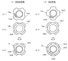
図11(a)は非加圧形態の加圧板スペーサー16を、(b)は加圧形態の加圧板スペーサー16を軸方向先端側から視た図である。(a-1)及び(b-1)は第1の加圧板部材16aを、(a-2)及び(b-2)は第2の加圧板部材16bを、そして(a-3)及び(b-3)は各加圧板部材を重畳した全体を示した図である。
11A is a view of the
図11(a)の非加圧形態では、(a-1)(a-2)に示すように加圧板部材16aと16bの各スペーサー突起16a2と16b2とが同じ角度位置にあるので、(a-3)に示すように軸方向から視てスペーサー突起16a2と16b2は完全に重なる。従って、隣り合うスペーサー突起同士の間には間隙d6が形成される。非加圧形態では、グラウトはこの間隙d6を通過可能である。従って、非加圧形態では、グラウトに対する加圧効果はほとんど無い。
In the non-pressurized form of FIG. 11A, the spacer projections 16a2 and 16b2 of the
図11(b)の加圧形態では、(b-1)(b-2)に示すように、加圧板部材16aと16bの各スペーサー突起16a2と16b2とが互いにずれた角度位置にある。図示の例では、2組のスペーサー突起同士が互いに45度ずれている。従って、(b-3)に示すように軸方向から視て、最外周縁が完全に円形となる。つまり、グラウトが通過する間隙d6が閉じられる。この加圧形態では、加圧板スペーサー16の先端側の面が加圧面として機能する。なお、各スペーサー突起の周方向の長さは、加圧形態において完全に閉じた円形を形成できるように設定する。
In the pressurization form of FIG. 11 (b), as shown in (b-1) and (b-2), the spacer protrusions 16a2 and 16b2 of the pressurizing
再び図9を参照し、補強構造体10Cを用いた老朽化モルタルの維持補修工法について説明する。先ず、老朽化モルタル吹付90及び地山100に対して削孔80を形成する。次に、削孔80の全体にグラウト70を注入する。この時点では、グラウトは無加圧の状態である。
With reference to FIG. 9 again, the maintenance repair method of the aging mortar using the reinforcing structure 10C will be described. First, the drilling holes 80 are formed in the aging
続いて、補強構造体10Cを削孔80内に挿入する。挿入当初は、加圧板スペーサー16を非加圧形態としておく。加圧板スペーサー16が非加圧形態の場合、補強構造体10Cの挿入抵抗は、鉄筋11のみの場合と同等である。加圧板スペーサー16がグラウト内に挿入された後、鉄筋11を軸周りに回動させる。このとき、第1の加圧板部材16aは鉄筋11と共に回動するのに対し、第2の加圧板部材16bは、脚部16b3による抵抗のために第1の加圧板部材16aの回動に追随しない。この結果、加圧板スペーサー16は加圧形態に移行する。非加圧形態から加圧形態へ移行したか否かは、挿入抵抗により確認できる。
Subsequently, the reinforcing structure 10 </ b> C is inserted into the
補強構造体10Cを用いる場合は、上述の第1の実施例又は第2の実施例のようにグラウトの排出又は注入の圧力を監視せず、専ら挿入抵抗を監視し調整することにより、内部圧力を制御する。加圧形態で挿入を続けると先端側のグラウトの圧力が上昇する。なお、各スペーサー突起16a2と16b2のずれの程度を調整することにより、グラウトが通過する間隙d6の大きさを変化させることができる。これを利用して挿入抵抗を調整できる。 When the reinforcing structure 10C is used, the internal pressure is not monitored by adjusting the insertion resistance without monitoring the grout discharge or injection pressure as in the first embodiment or the second embodiment. To control. If the insertion is continued in the pressurized state, the pressure of the grout on the tip side increases. Note that the size of the gap d6 through which the grout passes can be changed by adjusting the degree of displacement between the spacer protrusions 16a2 and 16b2. This can be used to adjust the insertion resistance.
なお、鉄筋11を逆方向に回動することにより、加圧板スペーサー16を加圧形態から非加圧形態へ移行させることもできる。例えば、挿入途中で不測の事態が生じて補強構造体10Cを一旦引き抜かなければならない場合、加圧形態から非加圧形態に戻すことにより、容易に引き抜くことが可能である。
In addition, by rotating the reinforcing
補強構造体10Cの挿入を完了した後、補強構造体10Cの基端部の頭部処理を行う(図12において説明する)。その後、新規モルタル吹付を行う。 After the insertion of the reinforcing structure 10C is completed, the head processing of the base end portion of the reinforcing structure 10C is performed (described in FIG. 12). Then, new mortar spraying is performed.
(4)頭部処理について
図12(a)は、補強構造体10Cの挿入完了後に行う頭部処理の一実施例を説明する断面図であり、(b)は(a)に示した連結鉄筋の平面図であり(c)はその側面図である。さらに、図12(d)は連結鉄筋の別の実施例の平面図、(e)はその側面図である。なお、図12において説明する頭部処理は、上述の第1及び第2の実施例の補強構造体10A、10Bについても同様に行うことができる。
(4) Head Processing FIG. 12A is a cross-sectional view for explaining an example of head processing performed after insertion of the reinforcing structure 10C is completed, and FIG. 12B is a connection reinforcing bar shown in FIG. (C) is a side view thereof. Furthermore, FIG.12 (d) is a top view of another Example of a connection reinforcing bar, (e) is the side view. In addition, the head process demonstrated in FIG. 12 can be performed similarly about
図12(a)に示すように、補強構造体10Cの基端部では、鉄筋11(第1の実施例では鉄筋11、第2の実施例では中空ボルト17)の頭部が老朽化モルタル吹付90から突出している。先ず、鉄筋11を貫通させて十字状の連結鉄筋20を設置し、さらに押圧板21及びワッシャー22を設置し、ナット23により締結する。これにより、補強構造体10の基端部が固定される。
As shown in FIG. 12 (a), at the base end portion of the reinforcing structure 10C, the head of the reinforcing bar 11 (the reinforcing
図12(b)に示すように、一実施例の十字状の連結鉄筋20は、2つの略長方形リング状鉄筋20a、20bを準備し、各々の長手方向中央部にて直角するように重ね合わされている。接合は、例えば、溶接又は締結による。重ねあわされた中央部の開口20cは、鉄筋11が貫通可能である。略長方形リング状鉄筋20a、20bの各々は、両端部が中央部に対して鈍角に折り曲げられている。
As shown in FIG. 12B, the cross-shaped connecting reinforcing
連結鉄筋20を固定する際は、図12(a)に示すように、連結鉄筋20の中央部を押圧変形させ、老朽化モルタル90の表面に当接させた状態で固定する。このとき、折り曲げられた両端部は、老朽化モルタル90の表面に載置されるので作業中に引っ掛かることが無く、また、老朽化モルタル90を地山に対して押圧する効果も得られる。
When fixing the connecting reinforcing
図12(d)(e)に示す別の実施例の連結鉄筋20Aは、(b)(c)の実施例の略長方形リング状鉄筋20aに替えて2本の鉄筋20a1、20a2を設け、略長方形リング状鉄筋20bに替えて2本の鉄筋20b1、20b2を設けている。いずれの鉄筋も両端部は中央部に対して鈍角に折り曲げられている。連結鉄筋20Aは、連結鉄筋20に比べて容易かつ安価に作製できる。
12 (d) and 12 (e), a connecting reinforcing
十字状の連結鉄筋のいずれの実施例も、2つの長尺の鉄筋要素を備えており、2つの鉄筋要素は、各々の長手方向中央部にて直交するように重ね合わされており、2つの鉄筋要素の各々は、平行に配置された2本の鉄筋を少なくとも具備しかつ2本の鉄筋の両端部は中央部に対して折り曲げられている。なお、1つの鉄筋要素において平行に配置される鉄筋の数は2本に限られず、偶数本(例えば4本)であればよい。 Each embodiment of the cross-shaped connecting reinforcing bar includes two long reinforcing bar elements, and the two reinforcing bar elements are stacked so as to be orthogonal to each other in the longitudinal center portion thereof. Each of the elements includes at least two reinforcing bars arranged in parallel, and both ends of the two reinforcing bars are bent with respect to the central part. In addition, the number of reinforcing bars arranged in parallel in one reinforcing bar element is not limited to two, and may be an even number (for example, four).
このような十字状の連結鉄筋20、20Aを用いることにより、ロープを使った足場での作業であっても容易にかつ短時間で、老朽化モルタル吹付の上に鉄筋を配置することができる。これにより法面作業が省力化され、効率的となる。
By using such cross-shaped connecting reinforcing
ここで、図9を再び参照する。図9には、十字状の連結鉄筋20を用いた頭部処理の別の実施例が示されている。図9では、鉄筋11の頭部に対し、先ず押圧板21を設置して第1のナット23aにて固定する。これは、補強構造体の挿入完了後、直ちに押圧板21を装着して頭部を締結固定することが必要な場合に行う。その後、十字状の連結鉄筋20を設置して第2のナット23bにて固定する。この場合は、図12(a)とは異なり、十字状の連結鉄筋20は変形していない。連結鉄筋20に替えて連結鉄筋20Aを用いてもよい。
Here, FIG. 9 will be referred to again. FIG. 9 shows another embodiment of the head processing using the cross-shaped connecting reinforcing
十字状の連結鉄筋20、20Aの別の利用例を説明する。通常、老朽化モルタル吹付に対し複数の補強構造体を設置するが、それらの間隔が広い場合には、適宜の中間位置に補助的な鉄筋挿入工を行う。補助的な鉄筋挿入工では、浅い削孔に短い鉄筋を挿入しモルタル充填する。そして、それらの短い鉄筋の頭部処理に十字状の連結鉄筋20、20Aを用いると好適である。これにより、老朽化モルタル吹付と新規モルタル吹付の一体化を向上させることができる。
Another example of use of the cross-shaped connecting reinforcing
(5)まとめ
本発明は、上述した各実施例に限定されるものではない。以下に本発明の全ての実施例に共通する特徴をまとめる。
本発明による補強構造体は、老朽化モルタル吹付の維持補修のために、老朽化モルタル吹付及び地山に形成した削孔に挿入されグラウトにより固定される補強構造体であって、削孔の略全長に亘る長さを有する補強用の棒状体と、棒状体の軸方向における1又は複数の位置にて棒状体を囲包して取り付けられかつ軸方向の先端側を向いた加圧面を形成可能である加圧手段と、を備えたことを特徴とする。
また、本発明による上記補強構造体を用いた老朽化モルタル吹付の維持補修工法は、老朽化モルタル吹付及び地山に削孔を形成する工程と、削孔の全体にグラウトを注入した後に当該削孔に補強構造体を挿入していくことにより、又は、削孔に補強構造体の全体を挿入した後に当該削孔にグラウトを注入していくことにより、加圧手段に形成された加圧面が当該加圧面よりも先端側のグラウトを加圧する工程と、を有することを特徴とする。
(5) Summary The present invention is not limited to the above-described embodiments. The features common to all the embodiments of the present invention are summarized below.
A reinforcing structure according to the present invention is a reinforcing structure that is inserted into a hole formed in an old mortar spray and a natural ground and is fixed by a grout in order to maintain and repair the old mortar spray. A reinforcing rod having a length extending over the entire length, and a pressure surface that surrounds and is attached to the rod at one or a plurality of positions in the axial direction of the rod and faces the tip in the axial direction. And pressurizing means.
In addition, the maintenance repair method for aging mortar spraying using the above reinforcing structure according to the present invention includes the steps of forming a drilling hole in the aging mortar spraying and the ground, and injecting the grout into the entire drilling hole. By inserting the reinforcing structure into the hole, or by inserting grout into the hole after inserting the entire reinforcing structure into the hole, the pressing surface formed in the pressing means is And a step of pressurizing the grout on the tip side of the pressing surface.
10A、10B、10C:補強構造体
11:鉄筋
12:鋼管
12a:孔
12b:先端面
13:加圧板
13a:加圧板内周縁
13b:加圧板外周縁
13c:加圧面
13d:弾性スペーサー
14:固定治具
16:加圧板スペーサー
16a:加圧板部材
16a1:環状部
16a2:スペーサー突起
16a3:固定軸部
16a4:回動制限溝
16b:加圧板部材
16b1:環状部
16b2:スペーサー突起
16b3:脚部
16b4:回動制限突起
17:中空ボルト
17a:先端開口
19:留め具
20、20A:十字連結鉄筋
21:押圧板
22:ワッシャー
23:ナット
60、60’:調整装置
61:排出注入治具
61’:注入治具
62:圧力計
63:開閉バルブ
64:排出注入ホース
65:止水治具
66:排気バルブ
70:グラウト
80:削孔
90:老朽化モルタル吹付
91:新規モルタル吹付
100:地山
101:地山表面
102:空洞
110:補強材
10A, 10B, 10C: Reinforcing structure 11: Reinforcing bar 12:
Claims (16)
前記削孔の略全長に亘る長さを有する補強用の棒状体(11、17)と、
前記棒状体(11、17)の軸方向における1又は複数の位置にて前記棒状体(11、17)を囲包して取り付けられかつ軸方向の先端側を向いた加圧面を形成可能である加圧手段(13、16)と、を備えたことを特徴とする補強構造体。 To maintain and repair the aging mortar spray (90), the reinforcement structure (10A, 10B) is inserted into the mortar spray (90) and the drill hole (80) formed in the natural ground (100) and fixed by the grout. , 10C)
A reinforcing rod-shaped body (11, 17) having a length over substantially the entire length of the hole,
It is possible to form a pressure surface which is attached to surround the rod-shaped body (11, 17) at one or a plurality of positions in the axial direction of the rod-shaped body (11, 17) and faces the tip side in the axial direction. And a pressurizing means (13, 16).
前記棒状体は、中実棒状体(11)であり、
前記中実棒状体(11)との間に所定の間隙(d2)を空けて同軸に配置されかつ前記加圧手段よりも基端側に延在する管状体(12)をさらに備え、
前記加圧手段は、前記管状体(12)の先端面(12b)に固定されかつ前記先端面(12b)よりも大径である環状平板の加圧板(13)であることを特徴とする補強構造体。 A reinforcing structure (10A) according to claim 1,
The rod-shaped body is a solid rod-shaped body (11),
A tubular body (12) disposed coaxially with a predetermined gap (d2) between the solid rod-shaped body (11) and extending proximally than the pressurizing means;
The pressurizing means is an annular flat pressure plate (13) that is fixed to the distal end surface (12b) of the tubular body (12) and has a larger diameter than the distal end surface (12b). Structure.
前記棒状体は、中空棒状体(17)であり、
前記中空棒状体(17)との間に所定の間隙(d2)を空けて同軸に配置されかつ前記加圧手段よりも基端側に延在する管状体(12)をさらに備え、
前記加圧手段は、前記管状体(12)の先端面(12b)に固定されかつ前記先端面(12b)よりも大径である環状の加圧板(13)であることを特徴とする補強構造体。 A reinforcing structure (10B) according to claim 1,
The rod-shaped body is a hollow rod-shaped body (17),
A tubular body (12) disposed coaxially with a predetermined gap (d2) between the hollow rod-shaped body (17) and extending proximally than the pressurizing means;
The pressurizing means is an annular pressure plate (13) fixed to the distal end surface (12b) of the tubular body (12) and having a larger diameter than the distal end surface (12b). body.
前記棒状体は、中実棒状体(11)であり、
前記加圧手段は、第1の加圧板部材(16a)と第2の加圧板部材(16b)とを軸方向に重畳した加圧板スペーサー(16)であり、
前記第1の加圧板部材(16a)は、前記中実棒状体(11)に固定され、第1の環状部(16a1)と該第1の環状部から径方向外側に突出する複数の第1のスペーサー突起(16a2)とを有し、
前記第2の加圧板部材(16b)は、前記中実棒状体(11)の軸周りに回動可能であり、第2の環状部(16b1)と該第2の環状部から径方向外側に突出する複数の第2のスペーサー突起(16b2)と該第2のスペーサー突起(16b2)から軸方向に突出する脚部(16b3)とを有し、かつ、
前記加圧板スペーサー(16)は、前記第1の加圧板部材(16a)に対して前記第2の加圧板部材(16b)が回動することにより、軸方向から視て、前記第1と第2のスペーサー突起(16a2,16b2)同士が互いに重なった非加圧形態と、前記第1と第2のスペーサー突起(16a2,16b2)同士が互いにずれて前記加圧面を形成した加圧形態との間で移行可能であることを特徴とする補強構造体。 A reinforcing structure (10C) according to claim 1,
The rod-shaped body is a solid rod-shaped body (11),
The pressure means is a pressure plate spacer (16) in which a first pressure plate member (16a) and a second pressure plate member (16b) are overlapped in the axial direction,
The first pressure plate member (16a) is fixed to the solid rod-like body (11) and has a first annular portion (16a1) and a plurality of first members protruding radially outward from the first annular portion. Spacer protrusion (16a2)
The second pressure plate member (16b) is rotatable around the axis of the solid rod-like body (11), and radially outward from the second annular portion (16b1) and the second annular portion. A plurality of protruding second spacer protrusions (16b2) and leg portions (16b3) protruding in the axial direction from the second spacer protrusions (16b2); and
When the second pressure plate member (16b) is rotated with respect to the first pressure plate member (16a), the pressure plate spacer (16) is viewed from the axial direction. A non-pressurized configuration in which two spacer projections (16a2, 16b2) overlap each other, and a pressurized configuration in which the first and second spacer projections (16a2, 16b2) are displaced from each other to form the pressurization surface Reinforcement structure characterized in that it can be transferred between.
老朽化モルタル吹付(90)及び地山(100)に削孔(80)を形成する工程と、
前記削孔(80)の全体にグラウト(70)を注入した後に該削孔(80)に前記補強構造体(10A、10C)を挿入していくことにより、又は、前記削孔(80)に前記補強構造体(10B)の全体を挿入した後に該削孔(80)にグラウト(70)を注入していくことにより、前記加圧手段(13、16)に形成された前記加圧面が該加圧面よりも先端側のグラウト(70)を加圧する工程と、を有することを特徴とする老朽化モルタル吹付の維持補修工法。 A maintenance repair method for aging mortar spraying using the reinforcing structure (10A, 10B, 10C) according to claim 1,
Forming the drilling holes (80) in the aging mortar spraying (90) and ground (100);
After injecting grout (70) into the whole hole (80), the reinforcing structure (10A, 10C) is inserted into the hole (80), or into the hole (80). By inserting the grout (70) into the drilling hole (80) after inserting the entire reinforcing structure (10B), the pressing surface formed on the pressing means (13, 16) is A method of maintaining and repairing aging mortar spraying, characterized by comprising a step of pressurizing the grout (70) on the tip side of the pressing surface.
老朽化モルタル吹付(90)及び地山(100)に削孔(80)を形成する工程と、
前記削孔(80)の全体にグラウト(70)を注入する工程と、
前記補強構造体(10A)を前記削孔(80)に挿入していくことにより、前記加圧板(13)が該加圧板(13)よりも先端側のグラウト(70)を加圧する工程と、を有することを特徴とする老朽化モルタル吹付の維持補修工法。 A maintenance repair method for aging mortar spraying using the reinforcing structure (10A) according to claim 2,
Forming the drilling holes (80) in the aging mortar spraying (90) and ground (100);
Injecting grout (70) into the entire hole drilling (80);
Inserting the reinforcing structure (10A) into the drilling hole (80) so that the pressure plate (13) presses the grout (70) on the tip side of the pressure plate (13); The maintenance repair method of the aging mortar spraying characterized by having.
前記補強構造体(10A)を前記削孔(80)に挿入する途中、前記加圧板(13)が前記削孔の入口を通過した直後に挿入を一時停止し、前記中実棒状体(11)と前記管状体(12)の間の間隙(d2)にグラウト(70)を注入し、その後、挿入を再開することを特徴とする老朽化モルタル吹付の維持補修工法。 In the maintenance repair method of aging mortar spraying according to claim 8,
During the insertion of the reinforcing structure (10A) into the drilling hole (80), the insertion is temporarily stopped immediately after the pressure plate (13) passes through the inlet of the drilling hole, and the solid rod-shaped body (11) A maintenance repair method for aging mortar spraying, characterized in that grout (70) is injected into the gap (d2) between the tubular body (12) and the insertion is resumed.
前記補強構造体(10A)を前記削孔(80)に挿入していく際、前記削孔(80)から排出されるグラウト(70)の量及び挿入速度のうち少なくとも一方を調整することにより、前記削孔(80)の内部圧力を制御することを特徴とする老朽化モルタル吹付の維持補修工法。 In the maintenance repair method of aging mortar spraying according to claim 8 or 9,
When inserting the reinforcing structure (10A) into the hole (80), by adjusting at least one of the amount of grout (70) discharged from the hole (80) and the insertion speed, A maintenance repair method for aging mortar spraying, characterized by controlling the internal pressure of the drilling hole (80).
前記補強構造体(10A)の挿入を完了した後、前記削孔(80)に二次グラウトを注入する工程を有することを特徴とする老朽化モルタル吹付の維持補修工法。 In the maintenance repair method of the aging mortar spraying according to any one of claims 8 to 10,
A method for maintaining and repairing aging mortar spraying, comprising the step of injecting secondary grout into the drilling hole (80) after the insertion of the reinforcing structure (10A) is completed.
老朽化モルタル吹付(90)及び地山(100)に削孔(80)を形成する工程と、
前記削孔(80)に前記補強構造体(10B)の全体を挿入する工程と、
前記補強構造体(10B)の前記中空棒状体(17)の中空を通してグラウト(70)を前記削孔(80)に注入していくことにより、前記加圧板(13)が該加圧板(13)よりも先端側のグラウト(70)を加圧する工程と、を有することを特徴とする老朽化モルタル吹付の維持補修工法。 A maintenance repair method for aging mortar spraying using the reinforcing structure (10B) according to claim 3,
Forming the drilling holes (80) in the aging mortar spraying (90) and ground (100);
Inserting the entire reinforcing structure (10B) into the hole drilling (80);
By injecting the grout (70) into the hole (80) through the hollow of the hollow rod-like body (17) of the reinforcing structure (10B), the pressure plate (13) is moved to the pressure plate (13). Pressurizing the grout (70) on the tip side of the mortar, and maintaining and repairing the aging mortar spraying.
前記中空棒状体(17)の中空を通してグラウト(70)を前記削孔(80)に注入していく際、前記中空棒状体(17)の中空に注入するグラウト(70)の量を調整することにより前記削孔(80)の内部圧力を制御することを特徴とする老朽化モルタル吹付の維持補修工法。 In the maintenance repair method of aging mortar spraying according to claim 12,
Adjusting the amount of grout (70) injected into the hollow of the hollow rod-shaped body (17) when the grout (70) is poured into the hole (80) through the hollow of the hollow rod-shaped body (17). A method for maintaining and repairing aging mortar spraying, characterized in that the internal pressure of the drilling hole (80) is controlled by the above.
老朽化モルタル吹付(90)及び地山(100)に削孔(80)を形成する工程と、
前記削孔(80)の全体にグラウト(70)を注入する工程と、
前記補強構造体(10C)の前記加圧板スペーサー(16)を前記非加圧形態として前記削孔(80)への挿入を開始し、挿入しつつ前記中実棒状体(11)を軸周りに回動させることにより前記加圧板スペーサー(16)を前記加圧形態へと移行させる工程と、
前記補強構造体(10C)を前記削孔(80)にさらに挿入していくことにより、前記加圧形態となった前記加圧板スペーサー(16)が該加圧板スペーサーよりも先端側のグラウト(70)を加圧する工程と、を有することを特徴とする老朽化モルタル吹付の維持補修工法。 A maintenance repair method for aging mortar spraying using the reinforcing structure (10C) according to claim 6,
Forming the drilling holes (80) in the aging mortar spraying (90) and ground (100);
Injecting grout (70) into the entire hole drilling (80);
The insertion of the reinforcing plate (10C) into the hole (80) is started with the pressure plate spacer (16) as the non-pressurized form, and the solid rod-like body (11) is moved around the axis while being inserted. Moving the pressure plate spacer (16) to the pressure mode by rotating;
By further inserting the reinforcing structure (10C) into the drilling hole (80), the pressure plate spacer (16) in the pressurization form is moved to the grout (70 on the tip side of the pressure plate spacer). A method of maintaining and repairing aging mortar spraying.
前記削孔(80)へのグラウト(70)の注入及び前記削孔(80)への前記補強構造体(10A、10B、10C)の挿入の双方を完了した後、前記補強構造体(10A、10B、10C)の基端部に十字状の連結鉄筋(20、20A)を取り付けた後に前記補強構造体(10A、10B、10C)の基端部を固定する工程と、
老朽化モルタル吹付(90)の上にモルタルを吹き付けることにより新規モルタル吹付(91)を形成する工程と、を有することを特徴とする老朽化モルタル吹付の維持補修工法。 In the maintenance repair method of the aging mortar spraying according to any one of claims 7 to 14,
After completing both the injection of the grout (70) into the drilling hole (80) and the insertion of the reinforcing structure (10A, 10B, 10C) into the drilling hole (80), the reinforcing structure (10A, Fixing the base end of the reinforcing structure (10A, 10B, 10C) after attaching the cross-shaped connecting reinforcing bars (20, 20A) to the base end of 10B, 10C);
A method for maintaining and repairing aging mortar spraying, comprising: forming a new mortar spraying (91) by spraying mortar on the aging mortar spraying (90).
2つの長尺の鉄筋要素を備え、
前記2つの鉄筋要素は、各々の長手方向中央部にて直交するように重ね合わされており、
前記2つの鉄筋要素の各々は、平行に配置された偶数本の鉄筋を少なくとも具備しかつ該偶数本の鉄筋の両端部は中央部に対して折り曲げられていることを特徴とする連結鉄筋。 The connection reinforcing bar (20, 20A) used in the maintenance repair method for aging mortar spraying according to claim 15,
With two long rebar elements,
The two reinforcing bar elements are superposed so as to be orthogonal to each other in the center in the longitudinal direction,
Each of the two reinforcing bar elements includes at least an even number of reinforcing bars arranged in parallel, and both ends of the even number of reinforcing bars are bent with respect to the central portion.
Priority Applications (1)
| Application Number | Priority Date | Filing Date | Title |
|---|---|---|---|
| JP2011027620A JP5622607B2 (en) | 2011-02-10 | 2011-02-10 | Reinforcing structure used in maintenance repair method for aging mortar spraying and its method |
Applications Claiming Priority (1)
| Application Number | Priority Date | Filing Date | Title |
|---|---|---|---|
| JP2011027620A JP5622607B2 (en) | 2011-02-10 | 2011-02-10 | Reinforcing structure used in maintenance repair method for aging mortar spraying and its method |
Publications (2)
| Publication Number | Publication Date |
|---|---|
| JP2012167452A true JP2012167452A (en) | 2012-09-06 |
| JP5622607B2 JP5622607B2 (en) | 2014-11-12 |
Family
ID=46971853
Family Applications (1)
| Application Number | Title | Priority Date | Filing Date |
|---|---|---|---|
| JP2011027620A Active JP5622607B2 (en) | 2011-02-10 | 2011-02-10 | Reinforcing structure used in maintenance repair method for aging mortar spraying and its method |
Country Status (1)
| Country | Link |
|---|---|
| JP (1) | JP5622607B2 (en) |
Cited By (6)
| Publication number | Priority date | Publication date | Assignee | Title |
|---|---|---|---|---|
| JP2013036226A (en) * | 2011-08-08 | 2013-02-21 | Okabe Co Ltd | Injection reinforcing rigid member for maintenance repair of cement mortar spray |
| JP2019027134A (en) * | 2017-07-31 | 2019-02-21 | 大成建設株式会社 | Ground improvement method |
| JP2019031836A (en) * | 2017-08-08 | 2019-02-28 | 日本基礎技術株式会社 | Repair and reinforcement methods for existing structures |
| CN113529577A (en) * | 2021-06-24 | 2021-10-22 | 中国五冶集团有限公司 | A large-scale support grouting device and grouting method |
| JP2022042095A (en) * | 2020-09-02 | 2022-03-14 | 株式会社イノアック住環境 | Repair method of sloped face |
| CN118814831A (en) * | 2024-09-19 | 2024-10-22 | 安徽省交通规划设计研究总院股份有限公司 | A kind of rock slope greening protection slope protection at the tunnel entrance |
Citations (5)
| Publication number | Priority date | Publication date | Assignee | Title |
|---|---|---|---|---|
| JPS5824017A (en) * | 1981-08-03 | 1983-02-12 | Raito Kogyo Kk | Soil stabilization work |
| JPH04216715A (en) * | 1990-12-12 | 1992-08-06 | Taisei Corp | Setting method for anchor tendon |
| JPH0752178Y2 (en) * | 1990-12-21 | 1995-11-29 | 建設基礎エンジニアリング株式会社 | Anchor hardening material injection device |
| JP2004176404A (en) * | 2002-11-27 | 2004-06-24 | Joto Kasei Kk | Cylindrical component capable of changing tip diameter |
| JP2006188839A (en) * | 2004-12-30 | 2006-07-20 | Nippon Kokyo Kikaku Kk | Pipe type double compression anchoring method |
-
2011
- 2011-02-10 JP JP2011027620A patent/JP5622607B2/en active Active
Patent Citations (5)
| Publication number | Priority date | Publication date | Assignee | Title |
|---|---|---|---|---|
| JPS5824017A (en) * | 1981-08-03 | 1983-02-12 | Raito Kogyo Kk | Soil stabilization work |
| JPH04216715A (en) * | 1990-12-12 | 1992-08-06 | Taisei Corp | Setting method for anchor tendon |
| JPH0752178Y2 (en) * | 1990-12-21 | 1995-11-29 | 建設基礎エンジニアリング株式会社 | Anchor hardening material injection device |
| JP2004176404A (en) * | 2002-11-27 | 2004-06-24 | Joto Kasei Kk | Cylindrical component capable of changing tip diameter |
| JP2006188839A (en) * | 2004-12-30 | 2006-07-20 | Nippon Kokyo Kikaku Kk | Pipe type double compression anchoring method |
Cited By (7)
| Publication number | Priority date | Publication date | Assignee | Title |
|---|---|---|---|---|
| JP2013036226A (en) * | 2011-08-08 | 2013-02-21 | Okabe Co Ltd | Injection reinforcing rigid member for maintenance repair of cement mortar spray |
| JP2019027134A (en) * | 2017-07-31 | 2019-02-21 | 大成建設株式会社 | Ground improvement method |
| JP2019031836A (en) * | 2017-08-08 | 2019-02-28 | 日本基礎技術株式会社 | Repair and reinforcement methods for existing structures |
| JP2022042095A (en) * | 2020-09-02 | 2022-03-14 | 株式会社イノアック住環境 | Repair method of sloped face |
| JP7497254B2 (en) | 2020-09-02 | 2024-06-10 | 株式会社イノアック住環境 | How to repair slopes |
| CN113529577A (en) * | 2021-06-24 | 2021-10-22 | 中国五冶集团有限公司 | A large-scale support grouting device and grouting method |
| CN118814831A (en) * | 2024-09-19 | 2024-10-22 | 安徽省交通规划设计研究总院股份有限公司 | A kind of rock slope greening protection slope protection at the tunnel entrance |
Also Published As
| Publication number | Publication date |
|---|---|
| JP5622607B2 (en) | 2014-11-12 |
Similar Documents
| Publication | Publication Date | Title |
|---|---|---|
| JP5622607B2 (en) | Reinforcing structure used in maintenance repair method for aging mortar spraying and its method | |
| JP4927662B2 (en) | Repair method for existing lining | |
| JP6991562B2 (en) | How to install anchor bolts, adhesive anchors and adhesive anchors for adhesive anchors | |
| CN105040726A (en) | Method for applying circular prestress on fan foundation connection | |
| JP2005200994A (en) | Joining structure of closed cross-sectional member | |
| JP6501940B2 (en) | Addition method and connection structure of casing segment in micro pile method | |
| JP2011032637A (en) | Joint structure and joint method for steel pipe pole | |
| JP6884663B2 (en) | Repair / reinforcement method for existing structures | |
| JP5775750B2 (en) | Steel pipe concrete composite pile | |
| JP2008202251A (en) | Reinforcing tool for concrete structure, and reinforcing structure and reinforcing construction method using the same | |
| JP5711035B2 (en) | Anchor and anchor fixing method | |
| JP5752510B2 (en) | Pressure bonding method for precast concrete members | |
| JP2002364182A (en) | Fluid injection plug | |
| EP1767710B1 (en) | Composite anchor bolt and construction method for the anchor bolt | |
| JP7178861B2 (en) | Concrete wall reinforcement method | |
| US12025167B2 (en) | System for securing an anchor in a mineral substrate | |
| JP2005023550A (en) | Outer wall repairing anchor pin | |
| JP2005023693A (en) | How to repair incomplete grout | |
| CN206581614U (en) | Threaded bar planting device | |
| JP7178860B2 (en) | Concrete wall reinforcement method | |
| JP2002364078A (en) | Resin combined anchor device | |
| JP4312643B2 (en) | Reinforcement method of block lining tunnel and its structure | |
| JP2001164896A (en) | Water stop method for concrete placing joint in direct concrete placing method | |
| JP7134057B2 (en) | Reinforcement member for reinforcement of concrete walls | |
| JP5525142B2 (en) | Repair structure, repair anchor and repair method |
Legal Events
| Date | Code | Title | Description |
|---|---|---|---|
| A621 | Written request for application examination |
Free format text: JAPANESE INTERMEDIATE CODE: A621 Effective date: 20130408 |
|
| A977 | Report on retrieval |
Free format text: JAPANESE INTERMEDIATE CODE: A971007 Effective date: 20140110 |
|
| A131 | Notification of reasons for refusal |
Free format text: JAPANESE INTERMEDIATE CODE: A131 Effective date: 20140128 |
|
| A521 | Request for written amendment filed |
Free format text: JAPANESE INTERMEDIATE CODE: A523 Effective date: 20140325 |
|
| TRDD | Decision of grant or rejection written | ||
| A01 | Written decision to grant a patent or to grant a registration (utility model) |
Free format text: JAPANESE INTERMEDIATE CODE: A01 Effective date: 20140902 |
|
| A61 | First payment of annual fees (during grant procedure) |
Free format text: JAPANESE INTERMEDIATE CODE: A61 Effective date: 20140922 |
|
| R150 | Certificate of patent or registration of utility model |
Ref document number: 5622607 Country of ref document: JP Free format text: JAPANESE INTERMEDIATE CODE: R150 |
|
| R250 | Receipt of annual fees |
Free format text: JAPANESE INTERMEDIATE CODE: R250 |
|
| R250 | Receipt of annual fees |
Free format text: JAPANESE INTERMEDIATE CODE: R250 |
|
| R250 | Receipt of annual fees |
Free format text: JAPANESE INTERMEDIATE CODE: R250 |
|
| S531 | Written request for registration of change of domicile |
Free format text: JAPANESE INTERMEDIATE CODE: R313531 |
|
| R350 | Written notification of registration of transfer |
Free format text: JAPANESE INTERMEDIATE CODE: R350 |
|
| R250 | Receipt of annual fees |
Free format text: JAPANESE INTERMEDIATE CODE: R250 |
|
| R250 | Receipt of annual fees |
Free format text: JAPANESE INTERMEDIATE CODE: R250 |
|
| R250 | Receipt of annual fees |
Free format text: JAPANESE INTERMEDIATE CODE: R250 |
|
| R250 | Receipt of annual fees |
Free format text: JAPANESE INTERMEDIATE CODE: R250 |
|
| R250 | Receipt of annual fees |
Free format text: JAPANESE INTERMEDIATE CODE: R250 |
|
| R250 | Receipt of annual fees |
Free format text: JAPANESE INTERMEDIATE CODE: R250 |