JP2004182014A - Steering column device - Google Patents
Steering column device Download PDFInfo
- Publication number
- JP2004182014A JP2004182014A JP2002348552A JP2002348552A JP2004182014A JP 2004182014 A JP2004182014 A JP 2004182014A JP 2002348552 A JP2002348552 A JP 2002348552A JP 2002348552 A JP2002348552 A JP 2002348552A JP 2004182014 A JP2004182014 A JP 2004182014A
- Authority
- JP
- Japan
- Prior art keywords
- steering column
- column device
- operation lever
- lever
- tilt
- Prior art date
- Legal status (The legal status is an assumption and is not a legal conclusion. Google has not performed a legal analysis and makes no representation as to the accuracy of the status listed.)
- Pending
Links
Images






Landscapes
- Steering Controls (AREA)
Abstract
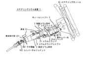
【課題】本発明は、テレスコピック機構のクランプ/アンクランプ機構とチルティング機構のクランプ/アンクランプ機構とをそれぞれ操作するために、対をなす操作レバーを備えたステアリングコラム装置において、通常は、使用頻度の高いチルティング機構に対してのみ操作できるようにすることを課題とする。
【解決手段】操作端7Cが折り畳まれた状態では、チルト操作レバー7Aとテレスコ操作レバー7Bの結合は解除され、操作端7Cが開かれた状態ではラッチ部材7Lが2つの操作レバーを結合状態にする。操作端7Cを折り畳んでこれを手前に引くと、チルト機構のみがアンクランプ状態(調整可能)になる。操作端7Cを開いた場合には、チルト機構とテレスコ機構について同時にアンクランプ状態になる。
【選択図】 図3An object of the present invention is to provide a steering column apparatus having a pair of operation levers for operating a clamp / unclamp mechanism of a telescopic mechanism and a clamp / unclamp mechanism of a tilting mechanism, respectively. It is an object to make it possible to operate only a frequent tilting mechanism.
When the operation end is folded, the connection between the tilt operation lever and the telescopic operation lever is released, and when the operation end is opened, the latch member connects the two operation levers. I do. When the operation end 7C is folded and pulled forward, only the tilt mechanism is in the unclamped state (adjustable). When the operation end 7C is opened, the tilt mechanism and the telescopic mechanism are simultaneously unclamped.
[Selection diagram] FIG.
Description
【0001】
【発明の属する技術分野】
本発明はステアリングコラム装置、特にテレスコピック機構、及び、チルティング機構の両方を備えた車両のためのステアリングコラム装置に関する。
【0002】
【従来の技術】
テレスコピック機構及びチルティング機構は、それぞれ運転者の体型及び好みにあわせて最も運転しやすい位置にステアリングホィールの前後方向位置、及び、傾斜角度を調整するための機構である。
【0003】
テレスコピック機構及びチルティング機構には、ステアリングホィールの前後方向位置、及び、傾斜角度を調整するときに操作されるクランプ/アンクランプ機構が備えられており、この調整時には、一旦、それぞれのためのクランプ/アンクランプ機構が解除され、その状態で前後方向位置、及び、傾斜角度を調整したのち、再度クランプ状態にされる。
【0004】
ステアリングホィールの前後方向位置、及び、傾斜角度の調整は、ステアリングホィールを手で操作することによって行うため、ステアリングホィールから手を離すことなくクランプ/アンクランプ機構を操作できる方が好ましい。英国特許出願公開2281375号には、ステアリングホィールに手をかけたまま操作できる単一の操作ハンドルを設けたステアリングコラム装置が開示されている。
【0005】
上記英国特許のステアリングコラム装置においては、操作ハンドルの動きはフレキシブルチューブ内を移動可能なケーブルを介して前後方向位置調整用のクランプ装置に伝達される。このケーブルとそのチューブはステアリングホィールの全調整範囲においてケーブルが自由に移動できる程度に曲率を充分小さくするため、大きなたわみが与えられている。このため、一部がステアリングコラム装置の外側に向かって飛び出すようになり見苦しいだけでなく、トラブルの原因ともなる。更に、ケーブルとそのチューブからなる伝動機構は信頼性に乏しいだけでなく、ケーブルが伸び縮みするため操作性が良好とはいえないものである。
【0006】
このような問題に対処するため、ステアリングホィールの近傍に設けられた単一のレバーによってテレスコピック機構及びチルティング機構の各クランプ/アンクランプ機構を操作できるようにし、ステアリングコラム装置から外側に大きくはみ出す部分が無く、信頼性が高く、操作性が良好なクランプ/アンクランプ機構を備えたステアリングコラム装置が提案(特願2002−273484号)されている。
【0007】
ステアリングホィールの前後方向位置、及び、傾斜角度の調整機能は運転時だけでなく、乗降のためにも使用される。これは、特に肥満あるいは妊婦運転者にとって、ステアリングホィールは腹部にぶつかり乗降の障害となるため、乗降時にこれを退避させることにより乗降を容易にするためである。ステアリングホィールをこのような目的のために退避させる場合には、チルティング(傾斜)機構によってステアリングホィールを車両前方に押しやれば十分である。ところが、上記英国特許あるいは上記日本出願のステアリングコラム装置においては、調整時にチルティング機構だけでなくテレスコピック機構のアンクランプがレバーの操作によって同時平行的に行われる構造となっている。そのため、レバーを操作するために大きい力が必要となるばかりでなく、アンクランプされたテレスコピック機構が動きやすいため動いたときには運転開始前に再度調整することが必要となる。
【0008】
【特許文献1】
英国特許出願公開2281375号明細書
【特許文献2】
米国特許第6237438号明細書
【0009】
【発明が解決しようとする課題】
本発明は、テレスコピック機構のクランプ/アンクランプ機構とチルティング機構のクランプ/アンクランプ機構とをそれぞれ操作するために、対をなす操作レバーを備えたステアリングコラム装置において、一方の操作レバーにのみ人が操作するための操作端を設け、この操作端を設けた操作レバーによって、通常は、使用頻度の高い方の(例えば、チルティング機構の)クランプ/アンクランプ機構のみを操作するようにし、使用頻度の低い方の(例えば、テレスコピック機構の)クランプ/アンクランプ機構を操作する必要が生じた場合には、この操作端に通常とは異なる操作を付加することにより両方のクランプ/アンクランプ機構を操作できるようにしたステアリングコラム装置を提供することを課題とする。
【0010】
【課題を解決するための手段】
上記課題は以下の手段によって解決される。すなわち、第1番目の発明は、ステアリングホィールを固定するためのホィールシャフト、上記ホィールシャフトの傾斜を調整することによって上記ステアリングホィールの傾斜を調整するためのチルトクランプ機構、上記ホィールシャフトの前後方向位置を調整することによって上記ステアリングホィールの前後方向位置を調整するテレスコクランプ機構、及び、上記各クランプ機構を操作するためのチルト操作レバーとテレスコ操作レバーからなる操作レバー対を備えたステアリングコラム装置において、上記操作レバー対の一方の操作レバーには、この操作レバーと他方の操作レバーとの間の結合/非結合を選択的に行うことができるラッチ部材が設けられていることを特徴とするステアリングコラム装置である。
【0011】
第2番目の発明は、第1番目の発明のステアリングコラム装置において、上記ラッチ部材は、上記操作レバー対を結合させる方向に付勢されていることを特徴とするステアリングコラム装置である。
【0012】
第3番目の発明は、第1番目又は第2番目の発明のステアリングコラム装置において、上記操作レバー対の各レバー中心軸は互いに共通の軸線上にあることを特徴とするステアリングコラム装置である。
【0013】
第4番目の発明は、第1番目から第3番目までのいずれかの発明のステアリングコラム装置において、上記ラッチ部材が設けられた操作レバーには、この上で可動な操作端が設けられており、この操作端の操作によって上記ラッチ部材による上記操作レバー対の結合/非結合が選択されることを特徴とするステアリングコラム装置である。
【0014】
第5番目の発明は、第1番目から第4番目までのいずれかの発明のステアリングコラム装置において、上記ラッチ部材は、一方の操作レバー上で揺動可能であり、他方のレバーに係合する係合ピンと、上記操作端の一部が当接する当接部を備えていることを特徴とするステアリングコラム装置である。
【0015】
第6番目の発明は、第5番目の発明のステアリングコラム装置において、上記操作端は、上記一方の操作レバーに折り畳み可能に設けられており、この操作端が折り畳まれた状態において上記当接部にこの操作端の一部が当接することによって、上記ラッチ部材による上記操作レバー対の非結合が選択されることを特徴とするステアリングコラム装置である。
【0016】
第7番目の発明は、第6番目の発明のステアリングコラム装置において、上記操作端は、折り畳み側に向って付勢されていることを特徴とするステアリングコラム装置である。
【0017】
第8番目の発明は、第5番目の発明のステアリングコラム装置において、上記操作端は、上記一方の操作レバーに沿って伸張縮退可能に設けられており、この操作端の縮退端において上記当接部にこの操作端の一部が当接することによって、上記ラッチ部材の非結合が選択されることを特徴とするステアリングコラム装置である。
【0018】
第9番目の発明は、第8番目の発明のステアリングコラム装置において、上記操作端は、縮退側に向って付勢されていることを特徴とするステアリングコラム装置である。
【0019】
第10番目の発明は、第1番目から第9番目までのいずれかの発明のステアリングコラム装置において、上記他方の操作レバーは、人が操作するための操作端を備えていないことを特徴とするステアリングコラム装置である。
【0020】
第11番目の発明は、第1番目から第10番目までのいずれかの発明のステアリングコラム装置において、上記操作レバー対の一方は、上記チルト操作レバーであり、他方は上記テレスコ操作レバーであることを特徴とするステアリングコラム装置である。
第12番目の発明は、第4番目から第11番目までのいずれかの発明のステアリングコラム装置において、上記操作端は、上記チルト操作レバーに設けられていることを特徴とするステアリングコラム装置である。
【0021】
【発明の実施の形態】
以下、図面に基づいて本発明の実施例を説明する。図1は、本発明実施例にかかるステアリングコラム装置1の外観図である。
【0022】
* 全体概要
ステアリングコラム装置1は、固定コラム部材2、移動コラム部材3、コラムヘッド31、チルトヘッド4、ホィールシャフト5、コラムクランプ21、チルトヘッドクランプ41(図2参照)、操作レバー対7、及び、機械的伝動装置を備えている。
【0023】
固定コラム部材2には、車体取付部221、222が備えられており、この車体取付部221、222によって車体91に取り付けられる。上記固定コラム部材2には、移動コラム部材3が中心軸回りに回転不能且つ中心軸方向に移動可能に支持されている。上記移動コラム部材3の一端側にはコラムヘッド31が備えられており、このコラムヘッド31にはチルトヘッド4がチルト中心軸43を中心としてチルト可能に支持されている。このチルトヘッド4にはホィールシャフト5が回転可能に支持されており、その一端にはステアリングホィール92が固定される。
【0024】
上記コラムヘッド31には、上記移動コラム部材3の中心軸と平行な軸のまわりに回転可能にコラムクランプシャフト6が設けられている。固定コラム部材2には、コラムクランプ21が備えられており、このコラムクランプ21は、上記コラムクランプシャフト6に対して相対的に移動可能であり、このコラムクランプシャフト6の回転によって、上記移動コラム部材3をクランプ/アンクランプ状態にすることができる。
【0025】
また、上記コラムヘッド31には、後述するチルトヘッドクランプ41が設けられており、上記チルトヘッド4をコラムヘッド31に対してクランプ/アンクランプする。上記チルトヘッド4には、レバー中心軸72(図3〜図8参照)によって操作レバー対7が支持されている。以下に示す例では操作レバー対7はチルト操作レバー7Aとテレスコ操作レバー7Bの対からなり、チルト操作レバー7Aがテレスコ操作レバー7Bの上側に配置されている。一方の側であるチルト操作レバー7Aには人が直接操作する折り畳み可能な操作端7Cが設けられている。これに対し、他方の側のテレスコ操作レバー7Bには、人が直接操作するような操作端7Cに相当するものは備えられていない。また、後述するように、チルト操作レバー7Aには、この操作レバー7Aと他方の操作レバー7Bとの間の結合/非結合を選択的に行うことができるラッチ部材7Lが設けられている。
【0026】
テレスコ操作レバー7Bの揺動は、機械的伝動装置を介して上記コラムクランプシャフト6の回転に変換され、この回転は上記コラムクランプ21に伝動され、移動コラム部材3のクランプ/アンクランプが行われる。また、チルト操作レバー7Aの揺動は上記チルトヘッドクランプ41に直接伝動され、チルトヘッド4のクランプ/アンクランプが行われる。上記ラッチ部材7Lによって、チルト操作レバー7Aとテレスコ操作レバー7Bとの間が結合されたときには、操作端7Cを手前に引くような操作によって2つのレバーが同時に揺動する。この揺動の結果、チルトヘッドクランプ41とコラムクランプ21とがともにアンクランプ状態になる。他方ラッチ部材7Lが結合していないときは、操作端7Cを手前に引くような操作はチルト操作レバー7Aのみを揺動させ、チルトヘッドクランプ41のみがアンクランプ状態になる。
【0027】
ホィールシャフト5の一端は、ステアリングコラム装置1内でユニバーサルジョイント931(図3)に接続され、更に、スプライン結合された一対の上中間軸941と下中間軸942(図3)、及び下側のユニバーサルジョイント932を介して、前車輪の方向を操作する機構へと接続されている。なお、図1中の点線は調整によってステアリングホィール92が取りうる位置と姿勢の幾例かを示している。
【0028】
* チルトヘッドクランプ
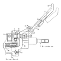
図2は、ステアリングコラム装置1の一部を切り欠いた図1の要部拡大側面図である。図3は、ステアリングコラム装置1を図2の上から(P方向)から見たときの一部切り欠き上面図である。この図3で、a、b、c、dは、それぞれ、操作端7Cが折り畳まれた状態(実線)、折り畳み状態のまま手前に引いた状態(b、点線)、操作端7Cを開いた状態(c、点線)、開いた状態で手前に引いた状態(d、点線)を示している。図4、図5は、ステアリングコラム装置1を図2の下から(Q方向から)見たときの、下面図であって、操作端7Cが折り畳まれた状態で操作されるときの説明図である。そして、図4は、図3のaに対応し、図5の実線部は同じくbに対応する。
【0029】
図6、図7は、図4、図5と同様の方向から見た図であって、操作端7Cが開かれた状態で操作されるときの説明図である。そして、図6は、図3のcに対応し、図7の実線部は同じくdに対応する。図8は、図2におけるA−A断面図、図9は図2におけるB−B断面図である。
【0030】
チルトヘッドクランプ41は次のような構成を備える。図2に示されるように移動コラム部材3には、チルト中心軸43にその中心を持つセグメントギヤ33がボルト34によって固定されており、セグメントギヤ33との間に空間を置いて背当部材341が設けられている。一方、上記空間内には、チルトヘッド4に軸441を中心として回動可能に支持されたギヤアーム44のギヤ部分442と、チルト操作レバー7Aに設けられた突出部71が入り込んでいる。
【0031】
上記ギヤアーム44は2本の脚からなるL字形状(図2)をなしており、一方の脚には上記ギヤ部分442が形成されている。上記ギヤアーム44の他方の脚443と上記突出部71の背部との間には付勢バネ711が介在し、突出部71の背部と脚443との間隔を押し広げるようなバイアスを与えている。
【0032】
このバイアスによって、突出部71が左方向(図2)に押され、ギヤ部分442を背後から押すため、ギヤ部分442がセグメントギヤ33に向けて押し付けられ、それぞれの歯が相互に噛合する。なお、ギヤ部分442がセグメントギヤ33を押すとき、突出部71にかかる反力は背当部材341が受ける(図2、図9)。これにより、チルト操作レバー7Aが図4、図6の位置にあるときチルトヘッド4が固定される。チルトヘッド4は、ギヤ部分442とセグメントギヤ33が噛合可能な角度位置において段階的な位置で固定される。
【0033】
チルト操作レバー7Aの突出部71が図2中で右方向に動くとき、付勢バネ711の押圧力によってギヤアーム44は図2において反時計回りに回転するため、これらの歯の噛合が外れる。したがって、チルト位置の調整時にチルト操作レバー7Aが図5、図7のように揺動すると、突出部71が右方向に動き、チルトヘッドクランプ41がアンクランプ状態に入る。
【0034】
* ユニバーサルジョイント及び中間軸
図3に示されるように、上中間軸941の端部とホィールシャフト5の端部との間には、上側のユニバーサルジョイント931が構成されている。ユニバーサルジョイント931の中心はチルト中心軸43の軸線上にあるため、チルトヘッド4がチルトしてもその影響を受けないようになっている。
【0035】
下中間軸942は固定コラム部材2に回転自在に支持されており、下中間軸942と上中間軸941がスプライン結合しているため、移動コラム部材3は図3の左右方向に移動可能になっている。スプライン結合によって移動位置に関わらず上中間軸941の回転は下中間軸942に伝達することが可能であり、ステアリングホィール92の前後方向位置を調整しても、ステアリングホィール92の回転を下中間軸942に伝達することができる。
【0036】
* 固定コラム部材と移動コラム部材
図2に示すように、移動コラム部材3の円筒部には、軸方向に沿った長穴32が形成されており、この長穴32内に固定コラム部材2に設けられたストッパ部材22が係合している。移動コラム部材3は、長穴32とストッパ部材22によって、固定コラム部材2からの抜け出しとこれに対する回転が防止されているため、固定コラム部材2内を長穴32の範囲で軸方向に移動可能となっている。
【0037】
固定コラム部材2は円筒状部231を備えており、円筒状部231の内部の2箇所にはリング状の摺動案内部232が設けられている(図3)。移動コラム部材3の円筒部外面はこの摺動案内部232によって移動コラム部材3の軸方向にがたつき無く移動可能になっている。コラムヘッド31の端面に設けられた緩衝ストッパ311は、調整時に移動コラム部材3が固定コラム部材2の端面に衝突したとき、金属同士の衝撃的な衝突を防止するために設けられた、ゴム、合成樹脂等でできた緩衝材である。
【0038】
* コラムクランプ
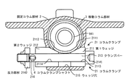
コラムクランプ21の構成を図10、図11、及び、図12を用いて説明する。図10は、図2におけるC−C断面図、図11、図12は図10における一部拡大図であって、コラムクランプシャフト6の回転位置とクランプ/アンクランプ状態の関係を示している。コラムクランプ21は、固定コラム部材2に設けられており、第1ウェッジ211、第2ウェッジ212、クランプバー213、及び、反力部材2141、2142を備えている。固定コラム部材2には横方向からウェッジ穴215があけられており、このウェッジ穴215の一部は固定コラム部材2の空洞に開口している。第1ウェッジ211、及び、第2ウェッジ212は、それぞれが傾斜面2111、2112を備えており、この傾斜面2111、2112の側を向かい合わせるようにウェッジ穴215内に納められている。2つのウェッジの傾斜面2111、2112は移動コラム部材3の円筒部外周と向き合うことになる。
【0039】
第1ウェッジ211、及び、第2ウェッジ212には、それぞれクランプバー穴2113、2114があけられており、この穴にクランプバー213が貫通している。クランプバー213の両端にはクランプバー穴2113、2114よりも外径の大きな反力部材2141、2142が固定されている。クランプバー213には一方の反力部材2142に接するようにコラムクランプシャフト穴216があけられており、この穴にコラムクランプシャフト6の実質的に楕円をなす非円形形状断面部が貫通している。
【0040】
コラムクランプシャフト6の一端には揺動アーム61が固定されている。コラムクランプシャフト6の非円形形状断面部は、アンクランプ時には図11のように楕円長径方向が大きく傾斜し、クランプ時には図12に示すように長径方向がクランプバー213の軸方向にほぼ近い方向を向く。この構成により、図11の状態から揺動アーム61に揺動回転を与えると、コラムクランプシャフト6が回転し、図12の状態になる。このとき、楕円長径部の一方の近傍が反力部材2142が左方向に押されることにより、クランプバー213が左方に引っ張られ、更に反力部材2141が第1ウェッジを左方に押すことになる。一方、第2ウェッジは楕円長径部の他方の近傍によって右方に押される。この結果2つのウェッジが相互に接近するため、それぞれの傾斜面2111、2112が移動コラム部材3の円筒部外周を押圧することになり、移動コラム部材3が固定コラム部材2に対してクランプされる。なお、第1ウェッジ211、及び、第2ウェッジ212は一体となってわずかながら左右に移動可能なため、一方のウェッジのみが移動コラム部材3を強く押圧するようなアンバランスは生じない。
【0041】
揺動アーム61を反対方向に揺動回転すると、上とは逆の動きによって第1ウェッジ211、及び、第2ウェッジ212が離反し、移動コラム部材3のクランプが解除される。
【0042】
* 操作レバー対の動き
次に操作レバー対7の動きとこれに連動する各部材について説明する。操作レバー対7はステアリングコラム装置1の下側に設けられており、図3には、この操作レバー対7(チルト操作レバー7A、テレスコ操作レバー7B)、この揺動の共通の中心となるレバー中心軸72、テレスコ操作レバー7Bに固定されたプッシャープレート73、及びプッシャーロッド74が部分的に見えている。図4、図5、図6、図7(これらの図は、図3と異なり下から見たときの図である点に注意)には、操作端7Cとラッチ部材7Lとの関係、この関係によって操作端7Cの操作が及ぼすチルト操作レバー7A、テレスコ操作レバー7Bの動きの違いについて説明されている。
【0043】
図13に示されるように、鍔742を備えているプッシャーロッド74は、コラムヘッド31上にチルト中心軸43と平行な方向に摺動自在に支持されている。プッシャーロッド74には鍔742を左方向に付勢する付勢バネ741を貫通しており、その端部にはその直角方向に長い小さな長穴743が設けられている。プッシャーロッド74の端部は、この長穴743を介して揺動アーム61の一端と軸係合している。長穴743はプッシャーロッド74が軸方向に移動したときに揺動アーム61との関係位置がずれる量を吸収するためのものである。
【0044】
付勢バネ741がプッシャーロッド74を左方向に付勢している。その右側先端で軸係合する揺動アーム61は時計方向の回転付勢力が付与されている。揺動アーム61に与えられた揺動付勢力はコラムクランプシャフト6をクランプ位置に維持する。このときの揺動アーム61の位置がそれぞれ実線で示されている。
【0045】
* プッシャープレート
チルトヘッド4は、コラムヘッド31上をチルトするため、チルトの量(角度)に応じて、プッシャープレート73に対するプッシャーロッド74の位置関係が変化する。図14には、チルトヘッド4をチルトさせた2つの位置を点線と実線で示す。プッシャーロッド74はコラムヘッドに支持されているためチルトによって位置を変えないが、プッシャープレート73はチルト中心軸43から離れているため、チルトヘッド4をチルトさせるときプッシャーロッド74との相対位置が変化する。このため、チルト量に関わらずプッシャーロッド74がプッシャープレート73に当接可能なようにプッシャープレート73にはホッケーのスティックのように曲がった広い当接面形状を持たせている。プッシャーロッド74は付勢バネ741によって図13左方向に付勢されてプッシャープレート73に当接している。クランプに関しては、チルトヘッド4は付勢バネ711の付勢力によってクランプされ、移動コラム部材3は付勢バネ741によってクランプされることになる。
【0046】
* 操作端とラッチ部材
操作端7Cは、図3等に示されるようにチルト操作レバー7Aに支持されており、ヒンジ軸7Hを中心として折り畳み可能である。ヒンジ軸7Hには、操作端7Cを手で操作したとき、クリック感が出るようにクリックヒンジ機構が内蔵されている。
【0047】
ラッチ部材7Lは、チルト操作レバー7Aに揺動可能に支持されており、ラッチピン7Pを備えている。チルト操作レバー7Aとテレスコ操作レバー7Bとはこの部分で接近してほぼ平行に並んでいる。このため図3の点線で示されるようにラッチ部材7Lの揺動位置によっては、ラッチピン7Pがテレスコ操作レバー7Bの端部と係合する。この係合によってチルト操作レバー7Aとテレスコ操作レバー7Bとは一体化される。
【0048】
操作端7Cが折り畳まれるとラッチ部材7Lの一部と係合する。この係合によって、ラッチ部材7Lが回動されラッチピン7Pとテレスコ操作レバー7Bとの係合が外れる。このため、操作端7Cを折り畳むと、チルト操作レバー7Aとテレスコ操作レバー7Bとの結合が解除(非結合)される。反対に、操作端7Cを開くとチルト操作レバー7Aとテレスコ操作レバー7Bとが結合状態になる。通常は、操作端7Cが折り畳まれた状態である。
【0049】
* ステアリングホィールの調整操作
以下、主として図3から図7までを用いて、ステアリングホィール92の前後方向位置、及び、傾斜角度を調整するときの操作と各部材の動作について説明する。運転時(ステアリングホィール92の前後方向位置、傾斜角度を調整しないとき)、図3のa、図4に示すように、操作端7Cは折り畳まれており、コラムクランプ21、チルトヘッドクランプ41はともにクランプ状態にある。
【0050】
** 傾斜角度の調整
ステアリングホィール92の角度を調整するとき、折り畳まれた操作端7Cを折り畳んだまま手前に引く(図3のb、図5)。操作端7Cが折り畳まれていることによって、チルト操作レバー7Aとテレスコ操作レバー7Bとの結合は断たれているため、チルト操作レバー7Aのみが図5に示されるように揺動する。
【0051】
チルト操作レバー7Aの揺動によって、突出部71が図2における右側に移動しギヤアーム44が反時計方向に回動する。ギヤアーム44の回動によって、セグメントギヤ33の歯とギヤアーム44のギヤ部分の歯との噛合が外れ、チルトヘッド4はチルト調整可能になる。上述のように、移動コラム部材3はクランプ状態であるため、チルティング機構のみの調整を行うことができる。単に乗降のためだけの場合はステアリングホィールを上方に押して(あるいはバネ45の付勢力によって)退避させて容易に降車することができ、更に操作端7Cはチルト操作レバー7Aを動かすだけのため小さい力で操作できる。頻繁に行われる乗降のための傾斜角度の調整が、最も簡単に操作できるようになっている。
【0052】
** 前後方向位置の調整
図6は、ステアリングホィール92の前後方向位置(ステアリングコラムの長さ)を調整するとき、それまで折り畳まれていた操作端7Cを図6点線のように開く。内蔵されているクリックヒンジ機構により一旦開いた操作端7Cは開いた状態を保つ。操作端7Cを開いたことにより、ラッチピン7Pがテレスコ操作レバー7Bの端部と係合する。この係合によってチルト操作レバー7Aとテレスコ操作レバー7Bとは一体化つまり、結合状態になる。
【0053】
このため、操作端7Cを図7に示すように手前(右)に引くと、チルト操作レバー7Aは上述の傾斜角度の調整のときと同様の動きをするのに加え、テレスコ操作レバー7Bが揺動する。この揺動によりプッシャープレート73が図7の実線の位置まで揺動し、付勢バネ741にうち勝ってプッシャーロッド74をこの図の上方に向けて押す。
【0054】
プッシャーロッド74のこの動きは、図13における右方向の動きであり、揺動アーム61の揺動を、したがって、コラムクランプシャフト6の反時計回り回動を起こす。コラムクランプシャフト6が回動すると、それまで図12に示すように長径部がほぼ水平の状態であったコラムクランプシャフト6は図11に示すように傾斜した状態になる。これによって図10のように接近していた第1ウェッジ211と第2ウェッジ212は、互いに離間するため移動コラム部材のクランプが解除される。この状態でステアリングホィール92の前後方向位置を調整する。したがって、操作端7Cを開いた状態のときこれを引くとチルト機構とテレスコピック機構の両方が調整可能になる。
【0055】
このように、操作レバー対7の一方の操作レバーには、この操作レバーと他方の操作レバーとの間の結合/非結合を選択的に行うことができるラッチ部材7Lが設けられており、ラッチ部材7Lが設けられた操作レバーには、この上で可動な操作端7Cの操作によってラッチ部材7Lによる操作レバー対7の結合/非結合を選択することができる。特にチルト操作レバー7Aにラッチ部材7Lを設けたので、頻繁に生じる乗降時のステアリングホィールの退避をチルトによって行うことができる。
【0056】
なお、チルトヘッドクランプ41が解除されたとき、チルトヘッド4には、その重量によりあたかも人が首をうなだれるときのような下向きの力が働く。このため、カウンターバランス用の強めのバネ45(図4、図5)が設けられており、このような力を相殺し、あるいは、さらにステアリングホィール92を最も上側の傾斜位置に維持するような力をチルトヘッド4に与えるようにしてある。これにより、乗降が容易にされている。
【0057】
操作端7Cから手を離すと、付勢バネ711及び付勢バネ741の力によって、チルト操作レバー7A及びテレスコ操作レバー7Bはもとの位置に戻り、それぞれがクランプ状態になる。また、開いていた場合には操作端7Cを折り畳み位置に返す。
【0058】
通常では折り畳まれている操作端7Cは、ステアリングホィールから充分に離れているため、ステアリングホィール92を操作するときに誤って手が触れてクランプが解除されることがない。
【0059】
図15及び図16は、操作端7Cを折り畳む構造のみを変更し、操作端7Cを、チルト操作レバー7Aに沿って伸張縮退可能にした例の説明図である。この場合の操作端7Cには、スプリング7Sが内蔵されており、このスプリング7Sによって縮退側に向って付勢されている。縮退端においてはラッチ部材7Lにこの操作端の一部が当接することによって、これを回動させ、図15に示されるようにラッチ部材7Lのラッチピン7Pとテレスコ操作レバー7Bとの係合が断たれた状態になっている。したがって、この状態で操作端7Cを揺動させる(手前に引く)と、チルト機構のみがアンクランプ状態にされ、ステアリングホィールの傾斜角の調整(はね上げ)が行われる。
【0060】
操作端7Cをスプリング7Sに逆らって伸張させたとき、ラッチ部材7Lのラッチピン7Pはテレスコ操作レバー7Bに係合するため、チルト操作レバー7Aとテレスコ操作レバー7Bは結合状態となり、操作レバー対7が一体的になる。この状態つまり、操作端7Cを伸張させたままこれを手前に引く(図16)と、2つのクランプはともに解除され、ステアリングホィール92の前後方向位置と傾斜角度を同時に調整することができる。
【0061】
操作端7Cから手を離すと、スプリング7Sによって操作端7Cは縮退するとともに、付勢バネ711及び付勢バネ741の力によって、チルト操作レバー7A及びテレスコ操作レバー7Bはもとの位置に戻り、それぞれがクランプ状態になる。通常では縮退しているため、操作端7Cがステアリングホィールから充分に離れることになるため、ステアリングホィール92の運転操作時に誤って手が触れてクランプが解除されるようなことはない。
【0062】
以上の例において、チルト操作レバー7Aとテレスコ操作レバー7Bとの関係を逆、すなわち、操作端7C及びラッチ部材7Lをテレスコ操作レバー7B側に設けるようにすることも可能である。また、ラッチ部材7Lは、不図示のスプリングによってラッチピン7Pとテレスコ操作レバー7Bとが係合する方向に付勢させる構造、あるいは自然に回動しない程度の適宜の摩擦力をラッチ部材7Lとチルト操作レバー7A間に与える構造等を適宜採用し、車体からの振動によるラッチ部材の意図しない回動や振動音の発生を防止することができる。
【0063】
以上の実施例のステアリングコラム装置によれば、テレスコピック機構のクランプ/アンクランプ機構とチルティング機構のクランプ/アンクランプ機構とをそれぞれ操作するために、対をなす操作レバーが備えられており、一方の操作レバーにのみ人が操作するための操作端を設け、この操作端を設けた操作レバーによって、通常は、チルティング機構のクランプ/アンクランプ機構のみを操作するようにしている。このようにすることにより、使用頻度が高いチルティング機構のクランプ/アンクランプについての操作を優先的に行わせ、使用頻度の低いテレスコピック機構について特に操作端に異なる操作を加えなければ変更が生じないようにしているため、必要最低限の操作、調整をすれば済むようになっている。また、ケーブルを用いていないためステアリングコラム装置から見苦しくはみ出す部分が無く、トラブルの発生も抑制でき、信頼性、操作性も向上させることができ、乗降毎に頻繁に行われる操作端の操作は、一方をアンクランプするだけであるため小さな力で操作できる。
【0064】
【発明の効果】
本発明のステアリングコラム装置によれば、テレスコピック機構のクランプ/アンクランプ機構とチルティング機構のクランプ/アンクランプ機構とをそれぞれ操作するために、対をなす操作レバーが備えられており、一方の操作レバーにのみ人が操作するための操作端を設け、この操作端を設けた操作レバーによって、通常は、使用頻度が高い方のクランプ/アンクランプ機構のみを優先的に操作するようにしており、使用頻度の低いテレスコピック機構について特に操作端に異なる操作を加えなければ変更が生じないようにしているため、通常の乗降時には必要最低限の操作、調整をすれば済むという効果を奏する。また、この操作には大きな力が必要とされないという効果を奏する。更に、ケーブルを用いていないためステアリングコラム装置から見苦しくはみ出す部分が無く、トラブルの発生も抑制でき、信頼性、操作性も向上させることができるという効果を奏する。
【図面の簡単な説明】
【図1】本発明実施例にかかるステアリングコラム装置1の外観図である。
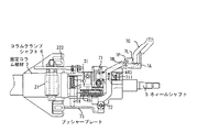
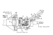
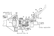
【図2】ステアリングコラム装置1の一部を切り欠いた図1の要部拡大図である。
【図3】ステアリングコラム装置1を図2の上から(P方向)から見たときの一部切り欠き上面図である。
【図4】ステアリングコラム装置1を図2の下から(Q方向から)見たときの、下面図であって、操作端7Cが折り畳まれた状態で操作されるときの説明図である。
【図5】ステアリングコラム装置1を図2の下から(Q方向から)見たときの、下面図であって、操作端7Cが折り畳まれた状態で操作されるときの説明図である。
【図6】ステアリングコラム装置1を図2の下から(Q方向から)見たときの、下面図であって、操作端7Cが開かれた状態で操作されるときの説明図である。
【図7】ステアリングコラム装置1を図2の下から(Q方向から)見たときの、下面図であって、操作端7Cが開かれた状態で操作されるときの説明図である。
【図8】図2におけるA−A断面図である。
【図9】図2におけるB−B断面図である。
【図10】図2におけるC−C断面図である。
【図11】図10における一部拡大図であって、コラムクランプシャフト6の回転位置とクランプ/アンクランプ状態の関係を示している。
【図12】図10における一部拡大図であって、コラムクランプシャフト6の回転位置とクランプ/アンクランプ状態の関係を示している。
【図13】図2におけるD−D断面図であって、プッシャープレート73、プッシャーロッド74、揺動アーム61の関係を示す説明図である。
【図14】チルトヘッド4をチルトさせたときの2つの位置を点線と実線で示す説明図である。
【図15】操作端7Cを、チルト操作レバー7Aに沿って伸張縮退可能にした例の説明図である。
【図16】操作端7Cを、チルト操作レバー7Aに沿って伸張縮退可能にした例の説明図である。
【符号の説明】
1 ステアリングコラム装置
2 固定コラム部材
21 コラムクランプ
211 第1ウェッジ
2111、2112 傾斜面
2113、2114 クランプバー穴
212 第2ウェッジ
213 クランプバー
2141、2142 反力部材
215 ウェッジ穴
216 コラムクランプシャフト穴
22 ストッパ部材
221、222 車体取付部
231 円筒状部
232 摺動案内部
3 移動コラム部材
31 コラムヘッド
311 緩衝ストッパ
32 長穴
33 セグメントギヤ
34 ボルト
341 背当部材
4 チルトヘッド
41 チルトヘッドクランプ
43 チルト中心軸
44 ギヤアーム
441 軸
442 ギヤ部分
443 脚
45 バネ
5 ホィールシャフト
6 コラムクランプシャフト
61 揺動アーム
7 操作レバー対
7A チルト操作レバー
7B テレスコ操作レバー
7C 操作端
7H ヒンジ軸
7L ラッチ部材
7P ラッチピン
7S スプリング
71 突出部
711 付勢バネ
72 レバー中心軸
73 プッシャープレート
74 プッシャーロッド
741 付勢バネ
742 鍔
743 長穴
91 車体
92 ステアリングホィール
931、932 ユニバーサルジョイント
941 上中間軸
942 下中間軸[0001]
TECHNICAL FIELD OF THE INVENTION
The present invention relates to a steering column device, and more particularly to a steering column device for a vehicle including both a telescopic mechanism and a tilting mechanism.
[0002]
[Prior art]
The telescopic mechanism and the tilting mechanism are mechanisms for adjusting the position of the steering wheel in the front-rear direction and the tilt angle to a position where the driver can most easily drive according to the body shape and preference of the driver.
[0003]
The telescopic mechanism and the tilting mechanism are provided with a clamp / unclamp mechanism that is operated when adjusting the front-rear position of the steering wheel and the tilt angle. / The unclamping mechanism is released, and in this state, the position in the front-rear direction and the inclination angle are adjusted, and then the state is again clamped.
[0004]
The adjustment of the front-rear position and the tilt angle of the steering wheel is performed by manually operating the steering wheel. Therefore, it is preferable that the clamp / unclamp mechanism can be operated without releasing the hand from the steering wheel. GB 2 281 375 discloses a steering column device provided with a single operating handle which can be operated with the hand on the steering wheel.
[0005]
In the steering column device of the above-mentioned British patent, the movement of the operating handle is transmitted to a clamp device for adjusting the position in the front-rear direction via a cable movable in a flexible tube. The cable and its tube are provided with a large deflection so that the curvature is small enough to allow the cable to move freely in the entire adjustment range of the steering wheel. As a result, a part of the steering column device protrudes toward the outside of the steering column device, which is not only unsightly but also causes a trouble. Further, the transmission mechanism comprising the cable and its tube is not only poor in reliability, but also has poor operability due to expansion and contraction of the cable.
[0006]
In order to cope with such a problem, the clamp / unclamp mechanism of the telescopic mechanism and the tilting mechanism can be operated by a single lever provided in the vicinity of the steering wheel. There has been proposed a steering column device provided with a clamp / unclamp mechanism which is highly reliable and has good operability (Japanese Patent Application No. 2002-273484).
[0007]
The function of adjusting the position of the steering wheel in the front-rear direction and the inclination angle is used not only for driving but also for getting on and off. This is because, especially for an obese or pregnant driver, the steering wheel collides with the abdomen and hinders getting on and off. When retracting the steering wheel for such a purpose, it is sufficient to push the steering wheel forward of the vehicle by a tilting (tilting) mechanism. However, the steering column device of the above-mentioned British patent or the above-mentioned Japanese application has a structure in which not only the tilting mechanism but also the unclamping of the telescopic mechanism is performed simultaneously and in parallel by operating a lever at the time of adjustment. Therefore, not only a large force is required to operate the lever, but also the unclamped telescopic mechanism is easy to move, so when it moves, it is necessary to readjust it before starting operation.
[0008]
[Patent Document 1]
UK Patent Application Publication No. 2281375
[Patent Document 2]
U.S. Pat. No. 6,237,438
[0009]
[Problems to be solved by the invention]
The present invention relates to a steering column apparatus having a pair of operation levers for operating a clamp / unclamp mechanism of a telescopic mechanism and a clamp / unclamp mechanism of a tilting mechanism, respectively. Is provided with an operating end for operating, and the operating lever provided with the operating end usually operates only the most frequently used clamp / unclamp mechanism (for example, of a tilting mechanism). If it becomes necessary to operate the less frequent clamp / unclamp mechanism (for example, of a telescopic mechanism), both clamp / unclamp mechanisms may be operated by adding an unusual operation to this operating end. It is an object to provide a steering column device that can be operated.
[0010]
[Means for Solving the Problems]
The above problem is solved by the following means. That is, a first invention is a wheel shaft for fixing a steering wheel, a tilt clamp mechanism for adjusting the inclination of the steering wheel by adjusting the inclination of the wheel shaft, and a front-rear position of the wheel shaft. A telescopic clamp mechanism that adjusts the position of the steering wheel in the front-rear direction by adjusting the position of the steering wheel, and a steering column device including an operation lever pair including a tilt operation lever and a telescopic operation lever for operating each of the clamp mechanisms, A steering column, characterized in that one of the operation levers of the pair of operation levers is provided with a latch member that can selectively perform connection / disconnection between the operation lever and the other operation lever. Device.
[0011]
A second invention is a steering column device according to the first invention, wherein the latch member is urged in a direction in which the operation lever pair is coupled.
[0012]
A third invention is a steering column device according to the first or second invention, wherein the lever central axes of the operation lever pair are on a common axis.
[0013]
According to a fourth aspect, in the steering column device according to any one of the first to third aspects, the operation lever provided with the latch member has an operation end movable thereon. And a connection / non-connection of the operation lever pair by the latch member by operation of the operation end.
[0014]
According to a fifth aspect, in the steering column device according to any one of the first to fourth aspects, the latch member can swing on one operation lever and engages with the other lever. A steering column device including an engagement pin and a contact portion with which a part of the operation end contacts.
[0015]
A sixth aspect of the present invention is the steering column device according to the fifth aspect, wherein the operating end is provided on the one operating lever so as to be foldable, and the abutting portion is provided when the operating end is folded. A part of the operating end abuts on the steering column device, so that disengagement of the operating lever pair by the latch member is selected.
[0016]
A seventh invention is a steering column device according to the sixth invention, wherein the operation end is urged toward the folding side.
[0017]
According to an eighth aspect of the present invention, in the steering column device according to the fifth aspect, the operating end is provided so as to be capable of extending and retracting along the one operating lever. A part of the operating end abuts on the portion to select disengagement of the latch member.
[0018]
A ninth aspect of the present invention is the steering column device according to the eighth aspect of the present invention, wherein the operating end is urged toward the retracted side.
[0019]
A tenth invention is characterized in that, in the steering column device according to any one of the first to ninth inventions, the other operation lever does not have an operation end for human operation. It is a steering column device.
[0020]
An eleventh invention is the steering column device according to any one of the first to tenth inventions, wherein one of the operation lever pairs is the tilt operation lever and the other is the telescopic operation lever. A steering column device characterized by the following.
A twelfth invention is the steering column device according to any one of the fourth to eleventh inventions, wherein the operation end is provided on the tilt operation lever. .
[0021]
BEST MODE FOR CARRYING OUT THE INVENTION
Hereinafter, embodiments of the present invention will be described with reference to the drawings. FIG. 1 is an external view of a steering column device 1 according to an embodiment of the present invention.
[0022]
* Overview
The steering column device 1 includes a fixed column member 2, a movable column member 3, a
[0023]
The fixed column member 2 is provided with vehicle
[0024]
The
[0025]
The
[0026]
The swing of the
[0027]
One end of the wheel shaft 5 is connected to a universal joint 931 (FIG. 3) in the steering column device 1, and further, is spline-coupled to a pair of an upper
[0028]
* Tilt head clamp
FIG. 2 is an enlarged side view of a main part of FIG. 1 with a part of the steering column device 1 cut away. FIG. 3 is a partially cutaway top view when the steering column device 1 is viewed from above (P direction) in FIG. In FIG. 3, a, b, c, and d indicate a state in which the operating
[0029]
FIGS. 6 and 7 are diagrams viewed from the same direction as FIGS. 4 and 5, and are explanatory diagrams when the operation is performed with the
[0030]
The tilt head clamp 41 has the following configuration. As shown in FIG. 2, a
[0031]
The gear arm 44 has an L-shape (FIG. 2) having two legs, and the
[0032]
The bias pushes the
[0033]
When the projecting
[0034]
* Universal joint and intermediate shaft
As shown in FIG. 3, an upper universal joint 931 is formed between the end of the upper
[0035]
Since the lower
[0036]
* Fixed and movable column members
As shown in FIG. 2, an elongated hole 32 is formed in the cylindrical portion of the movable column member 3 along the axial direction, and a stopper member 22 provided on the fixed column member 2 is engaged in the elongated hole 32. I agree. Since the movable column member 3 is prevented from coming out of the fixed column member 2 and rotating with respect to the fixed column member 2 by the elongated hole 32 and the stopper member 22, the movable column member 3 can be axially moved within the fixed column member 2 within the range of the elongated hole 32. It has become.
[0037]
The fixed column member 2 has a cylindrical portion 231, and ring-shaped sliding
[0038]
* Column clamp
The configuration of the
[0039]
The first wedge 211 and the second wedge 212 are provided with
[0040]
A
[0041]
When the
[0042]
* Operation lever pair movement
Next, the movement of the operation lever pair 7 and each member linked thereto will be described. The operation lever pair 7 is provided on the lower side of the steering column device 1. FIG. 3 shows the operation lever pair 7 (
[0043]
As shown in FIG. 13, the
[0044]
An urging spring 741 urges the
[0045]
* Pusher plate
Since the tilt head 4 tilts on the
[0046]
* Operating end and latch member
The operation end 7C is supported by a
[0047]
The latch member 7L is swingably supported by the
[0048]
When the
[0049]
* Steering wheel adjustment
Hereinafter, the operation of adjusting the position of the steering wheel 92 in the front-rear direction and the inclination angle and the operation of each member will be described mainly with reference to FIGS. 3 to 7. During operation (when the front-rear position and the inclination angle of the steering wheel 92 are not adjusted), as shown in FIGS. 3A and 4, the
[0050]
** Adjusting the tilt angle
When adjusting the angle of the steering wheel 92, the folded
[0051]
By the swing of the
[0052]
** Adjusting the position in the front-back direction
In FIG. 6, when the front-rear position (the length of the steering column) of the steering wheel 92 is adjusted, the operating
[0053]
For this reason, when the
[0054]
This movement of the
[0055]
As described above, one of the operation levers of the operation lever pair 7 is provided with the latch member 7L that can selectively perform connection / non-connection between the operation lever and the other operation lever. With the operation lever provided with the member 7L, the connection / non-connection of the operation lever pair 7 by the latch member 7L can be selected by operating the movable operation end 7C thereon. In particular, since the latch member 7L is provided on the
[0056]
When the tilt head clamp 41 is released, a downward force acts on the tilt head 4 as if the person were to bow his or her neck due to its weight. For this reason, a strong counter-balancing spring 45 (FIGS. 4 and 5) is provided to offset such a force or to maintain the steering wheel 92 in the uppermost inclined position. To the tilt head 4. This facilitates getting on and off.
[0057]
When the hand is released from the operating
[0058]
Normally, the folded
[0059]
FIGS. 15 and 16 are explanatory diagrams of an example in which only the structure for folding the
[0060]
When the operating
[0061]
When the hand is released from the operation end 7C, the
[0062]
In the above example, the relationship between the
[0063]
According to the steering column device of the above embodiment, a pair of operation levers are provided for operating the clamp / unclamp mechanism of the telescopic mechanism and the clamp / unclamp mechanism of the tilting mechanism, respectively. Only the operation lever is provided with an operation end for human operation, and the operation lever provided with the operation end normally operates only the clamp / unclamp mechanism of the tilting mechanism. By doing so, the operation for clamping / unclamping of the tilting mechanism that is frequently used is preferentially performed, and no change occurs unless a different operation is applied to the operation end of the telescopic mechanism that is less frequently used. As a result, the minimum necessary operations and adjustments are required. Also, since no cable is used, there is no part that protrudes unsightly from the steering column device, the occurrence of troubles can be suppressed, reliability and operability can be improved, and the operation of the operation end that is frequently performed every time getting on and off, Since only one of them is unclamped, it can be operated with a small force.
[0064]
【The invention's effect】
According to the steering column device of the present invention, a pair of operation levers is provided for operating the clamp / unclamp mechanism of the telescopic mechanism and the clamp / unclamp mechanism of the tilting mechanism, respectively. Only the lever is provided with an operation end for human operation, and the operation lever provided with this operation end normally operates only the most frequently used clamp / unclamp mechanism preferentially. Since the telescopic mechanism which is used less frequently is not changed unless a different operation is applied to the operation end, there is an effect that the necessary minimum operation and adjustment can be performed during normal getting on and off. Also, there is an effect that a large force is not required for this operation. Furthermore, since no cable is used, there is no portion that protrudes unsightly from the steering column device, the occurrence of troubles can be suppressed, and reliability and operability can be improved.
[Brief description of the drawings]
FIG. 1 is an external view of a steering column device 1 according to an embodiment of the present invention.
FIG. 2 is an enlarged view of a main part of FIG. 1 with a part of the steering column device 1 cut away.
3 is a partially cutaway top view when the steering column device 1 is viewed from above (P direction) in FIG.
4 is a bottom view when the steering column device 1 is viewed from below (from the Q direction) in FIG. 2, and is an explanatory diagram when the
5 is a bottom view when the steering column device 1 is viewed from below (from the Q direction) in FIG. 2, and is an explanatory diagram when the
6 is a bottom view when the steering column device 1 is viewed from below (from the Q direction) in FIG. 2, and is an explanatory view when the steering column device 1 is operated with the
7 is a bottom view when the steering column device 1 is viewed from below (from the Q direction) in FIG. 2, and is an explanatory diagram when the steering column device 1 is operated with the operating
FIG. 8 is a sectional view taken along the line AA in FIG. 2;
FIG. 9 is a sectional view taken along line BB in FIG. 2;
FIG. 10 is a sectional view taken along the line CC in FIG. 2;
11 is a partially enlarged view of FIG. 10 and shows a relationship between a rotational position of a column clamp shaft 6 and a clamped / unclamped state.
12 is a partially enlarged view of FIG. 10 and shows a relationship between a rotational position of a column clamp shaft 6 and a clamp / unclamp state.
13 is a cross-sectional view taken along the line DD in FIG. 2, and is an explanatory diagram showing a relationship among a
FIG. 14 is an explanatory diagram showing two positions when the tilt head 4 is tilted by a dotted line and a solid line.
FIG. 15 is an explanatory diagram of an example in which an
FIG. 16 is an explanatory diagram of an example in which an
[Explanation of symbols]
1 Steering column device
2 Fixed column members
21 Column clamp
211 First wedge
2111, 2112 Inclined surface
2113, 2114 Clamp bar hole
212 2nd wedge
213 Clamp bar
2141, 2142 Reaction force member
215 wedge hole
216 Column clamp shaft hole
22 Stopper member
221, 222 Body mounting part
231 cylindrical part
232 Sliding guide
3 Moving column member
31 Column head
311 Buffer stopper
32 long hole
33 segment gear
34 volts
341 Backrest member
4 Tilt head
41 Tilt head clamp
43 Tilt center axis
44 Gear arm
441 axes
442 Gear part
443 legs
45 spring
5 Wheel shaft
6 Column clamp shaft
61 Swing arm
7 Operation lever pair
7A tilt operation lever
7B Telescopic operation lever
7C Operation terminal
7H hinge axis
7L latch member
7P Latch pin
7S spring
71 Projection
711 biasing spring
72 lever center axis
73 pusher plate
74 pusher rod
741 biasing spring
742 Tsuba
743 long hole
91 Body
92 Steering wheel
931, 932 Universal joint
941 Upper middle shaft
942 Lower intermediate shaft
Claims (12)
上記ホィールシャフトの傾斜を調整することによって上記ステアリングホィールの傾斜を調整するためのチルトクランプ機構、
上記ホィールシャフトの前後方向位置を調整することによって上記ステアリングホィールの前後方向位置を調整するテレスコクランプ機構、及び、
上記各クランプ機構を操作するためのチルト操作レバーとテレスコ操作レバーからなる操作レバー対
を備えたステアリングコラム装置において、
上記操作レバー対の一方の操作レバーには、この操作レバーと他方の操作レバーとの間の結合/非結合を選択的に行うことができるラッチ部材が設けられていること
を特徴とするステアリングコラム装置。A wheel shaft for fixing the steering wheel,
A tilt clamp mechanism for adjusting the inclination of the steering wheel by adjusting the inclination of the wheel shaft;
A telescopic clamp mechanism that adjusts the front-rear position of the steering wheel by adjusting the front-rear position of the wheel shaft; and
In a steering column device including an operation lever pair including a tilt operation lever and a telescopic operation lever for operating each of the clamp mechanisms,
A steering column, characterized in that one of the operation levers of the pair of operation levers is provided with a latch member that can selectively perform connection / disconnection between the operation lever and the other operation lever. apparatus.
上記ラッチ部材は、上記操作レバー対を結合させる方向に付勢されていることを特徴とするステアリングコラム装置。The steering column device according to claim 1,
The steering column device, wherein the latch member is biased in a direction in which the pair of operation levers are coupled.
上記操作レバー対の各レバー中心軸は互いに共通の軸線上にあること
を特徴とするステアリングコラム装置。In the steering column device according to any one of claims 1 and 2,
A steering column device wherein the lever central axes of the operating lever pair are on a common axis.
上記ラッチ部材が設けられた操作レバーには、この上で可動な操作端が設けられており、この操作端の操作によって上記ラッチ部材による上記操作レバー対の結合/非結合が選択されること
を特徴とするステアリングコラム装置。In the steering column device according to any one of claims 1 to 3,
The operation lever provided with the latch member is provided with a movable operation end on which the operation lever is operated, and the operation of the operation end is used to select connection / disconnection of the operation lever pair by the latch member. Characteristic steering column device.
上記ラッチ部材は、一方の操作レバー上で揺動可能であり、他方のレバーに係合する係合ピンと、上記操作端の一部が当接する当接部を備えていること
を特徴とするステアリングコラム装置。In the steering column device according to any one of claims 1 to 4,
The steering member is characterized in that the latch member is swingable on one operation lever, and has an engagement pin engaged with the other lever, and a contact portion with which a part of the operation end contacts. Column device.
上記操作端は、上記一方の操作レバーに折り畳み可能に設けられており、この操作端が折り畳まれた状態において上記当接部にこの操作端の一部が当接することによって、上記ラッチ部材による上記操作レバー対の非結合が選択されること
を特徴とするステアリングコラム装置。The steering column device according to claim 5,
The operating end is provided on the one operating lever so as to be foldable, and when the operating end partially abuts on the abutting portion in a state where the operating end is folded, the operating end of the latch member is used. A steering column device, wherein non-connection of an operation lever pair is selected.
上記操作端は、折り畳み側に向って付勢されていること
を特徴とするステアリングコラム装置。The steering column device according to claim 6,
The steering column device, wherein the operation end is biased toward a folding side.
上記操作端は、上記一方の操作レバーに沿って伸張縮退可能に設けられており、この操作端の縮退端において上記当接部にこの操作端の一部が当接することによって、上記ラッチ部材の非結合が選択されること
を特徴とするステアリングコラム装置。The steering column device according to claim 5,
The operating end is provided so as to be capable of extending and retracting along the one operating lever, and a part of the operating end abuts on the contact portion at the retracting end of the operating end, whereby the latch member A steering column device wherein non-connection is selected.
上記操作端は、縮退側に向って付勢されていること
を特徴とするステアリングコラム装置。The steering column device according to claim 8,
The steering column device, wherein the operating end is biased toward a retracted side.
上記他方の操作レバーは、人が操作するための操作端を備えていないこと
を特徴とするステアリングコラム装置。The steering column device according to any one of claims 1 to 9,
The steering column device, wherein the other operation lever does not have an operation end for human operation.
上記操作レバー対の一方は、上記チルト操作レバーであり、他方は上記テレスコ操作レバーであること
を特徴とするステアリングコラム装置。The steering column device according to any one of claims 1 to 10,
A steering column device, wherein one of the operation lever pairs is the tilt operation lever, and the other is the telescopic operation lever.
上記操作端は、上記チルト操作レバーに設けられていること
を特徴とするステアリングコラム装置。In the steering column device according to any one of claims 4 to 11,
The steering column device, wherein the operation end is provided on the tilt operation lever.
Priority Applications (1)
| Application Number | Priority Date | Filing Date | Title |
|---|---|---|---|
| JP2002348552A JP2004182014A (en) | 2002-11-29 | 2002-11-29 | Steering column device |
Applications Claiming Priority (1)
| Application Number | Priority Date | Filing Date | Title |
|---|---|---|---|
| JP2002348552A JP2004182014A (en) | 2002-11-29 | 2002-11-29 | Steering column device |
Publications (1)
| Publication Number | Publication Date |
|---|---|
| JP2004182014A true JP2004182014A (en) | 2004-07-02 |
Family
ID=32751440
Family Applications (1)
| Application Number | Title | Priority Date | Filing Date |
|---|---|---|---|
| JP2002348552A Pending JP2004182014A (en) | 2002-11-29 | 2002-11-29 | Steering column device |
Country Status (1)
| Country | Link |
|---|---|
| JP (1) | JP2004182014A (en) |
Cited By (1)
| Publication number | Priority date | Publication date | Assignee | Title |
|---|---|---|---|---|
| WO2009106257A1 (en) * | 2008-02-28 | 2009-09-03 | Thysssenkrupp Presta Aktiengesellschaft | Adjustable steering column for a motor vehicle |
-
2002
- 2002-11-29 JP JP2002348552A patent/JP2004182014A/en active Pending
Cited By (1)
| Publication number | Priority date | Publication date | Assignee | Title |
|---|---|---|---|---|
| WO2009106257A1 (en) * | 2008-02-28 | 2009-09-03 | Thysssenkrupp Presta Aktiengesellschaft | Adjustable steering column for a motor vehicle |
Similar Documents
| Publication | Publication Date | Title |
|---|---|---|
| US7552945B2 (en) | Steering column for motor vehicle | |
| US20100007167A1 (en) | Vehicle seat | |
| JP2004262433A (en) | Steering column device | |
| CN101511636A (en) | Vehicle seat | |
| KR100530030B1 (en) | Tilt steering apparatus for vehicle | |
| JP2005014681A (en) | Steering column device for vehicle | |
| JP2005088755A (en) | Steering column device | |
| JP2008174010A (en) | Caster and stroller having the caster | |
| JP6186158B2 (en) | Seat operating device and vehicle seat | |
| JP2004224208A (en) | Steering column device | |
| JP2004203114A (en) | Steering column device | |
| JP3972778B2 (en) | Steering column device | |
| JP2004196038A (en) | Steering column device | |
| JP4192922B2 (en) | Steering column device | |
| JP4110927B2 (en) | Steering column device | |
| JP4411049B2 (en) | Steering column device | |
| JP2004161028A (en) | Steering column device | |
| JP2008007096A (en) | Steering device | |
| JP2004082846A (en) | Steering column device | |
| JP4506176B2 (en) | Steering column device | |
| JP2004155281A (en) | Steering column device | |
| KR100569953B1 (en) | Steering column of car | |
| JP4439891B2 (en) | Steering column device | |
| JP2004090905A (en) | Tilt steering system for vehicles | |
| JP2007062662A (en) | Steering column device |