JP2004190672A - Active thrust control system for combined cycle steam turbine with large bleed - Google Patents
Active thrust control system for combined cycle steam turbine with large bleed Download PDFInfo
- Publication number
- JP2004190672A JP2004190672A JP2003406754A JP2003406754A JP2004190672A JP 2004190672 A JP2004190672 A JP 2004190672A JP 2003406754 A JP2003406754 A JP 2003406754A JP 2003406754 A JP2003406754 A JP 2003406754A JP 2004190672 A JP2004190672 A JP 2004190672A
- Authority
- JP
- Japan
- Prior art keywords
- steam
- pressure section
- outlet
- valve
- flow path
- Prior art date
- Legal status (The legal status is an assumption and is not a legal conclusion. Google has not performed a legal analysis and makes no representation as to the accuracy of the status listed.)
- Granted
Links
Images



Classifications
-
- F—MECHANICAL ENGINEERING; LIGHTING; HEATING; WEAPONS; BLASTING
- F01—MACHINES OR ENGINES IN GENERAL; ENGINE PLANTS IN GENERAL; STEAM ENGINES
- F01D—NON-POSITIVE DISPLACEMENT MACHINES OR ENGINES, e.g. STEAM TURBINES
- F01D3/00—Machines or engines with axial-thrust balancing effected by working-fluid
- F01D3/04—Machines or engines with axial-thrust balancing effected by working-fluid axial thrust being compensated by thrust-balancing dummy piston or the like
-
- F—MECHANICAL ENGINEERING; LIGHTING; HEATING; WEAPONS; BLASTING
- F01—MACHINES OR ENGINES IN GENERAL; ENGINE PLANTS IN GENERAL; STEAM ENGINES
- F01D—NON-POSITIVE DISPLACEMENT MACHINES OR ENGINES, e.g. STEAM TURBINES
- F01D1/00—Non-positive-displacement machines or engines, e.g. steam turbines
- F01D1/02—Non-positive-displacement machines or engines, e.g. steam turbines with stationary working-fluid guiding means and bladed or like rotor, e.g. multi-bladed impulse steam turbines
- F01D1/023—Non-positive-displacement machines or engines, e.g. steam turbines with stationary working-fluid guiding means and bladed or like rotor, e.g. multi-bladed impulse steam turbines the working-fluid being divided into several separate flows ; several separate fluid flows being united in a single flow; the machine or engine having provision for two or more different possible fluid flow paths
-
- F—MECHANICAL ENGINEERING; LIGHTING; HEATING; WEAPONS; BLASTING
- F01—MACHINES OR ENGINES IN GENERAL; ENGINE PLANTS IN GENERAL; STEAM ENGINES
- F01D—NON-POSITIVE DISPLACEMENT MACHINES OR ENGINES, e.g. STEAM TURBINES
- F01D3/00—Machines or engines with axial-thrust balancing effected by working-fluid
-
- F—MECHANICAL ENGINEERING; LIGHTING; HEATING; WEAPONS; BLASTING
- F01—MACHINES OR ENGINES IN GENERAL; ENGINE PLANTS IN GENERAL; STEAM ENGINES
- F01D—NON-POSITIVE DISPLACEMENT MACHINES OR ENGINES, e.g. STEAM TURBINES
- F01D3/00—Machines or engines with axial-thrust balancing effected by working-fluid
- F01D3/02—Machines or engines with axial-thrust balancing effected by working-fluid characterised by having one fluid flow in one axial direction and another fluid flow in the opposite direction
-
- F—MECHANICAL ENGINEERING; LIGHTING; HEATING; WEAPONS; BLASTING
- F01—MACHINES OR ENGINES IN GENERAL; ENGINE PLANTS IN GENERAL; STEAM ENGINES
- F01K—STEAM ENGINE PLANTS; STEAM ACCUMULATORS; ENGINE PLANTS NOT OTHERWISE PROVIDED FOR; ENGINES USING SPECIAL WORKING FLUIDS OR CYCLES
- F01K23/00—Plants characterised by more than one engine delivering power external to the plant, the engines being driven by different fluids
- F01K23/02—Plants characterised by more than one engine delivering power external to the plant, the engines being driven by different fluids the engine cycles being thermally coupled
- F01K23/06—Plants characterised by more than one engine delivering power external to the plant, the engines being driven by different fluids the engine cycles being thermally coupled combustion heat from one cycle heating the fluid in another cycle
- F01K23/10—Plants characterised by more than one engine delivering power external to the plant, the engines being driven by different fluids the engine cycles being thermally coupled combustion heat from one cycle heating the fluid in another cycle with exhaust fluid of one cycle heating the fluid in another cycle
- F01K23/106—Plants characterised by more than one engine delivering power external to the plant, the engines being driven by different fluids the engine cycles being thermally coupled combustion heat from one cycle heating the fluid in another cycle with exhaust fluid of one cycle heating the fluid in another cycle with water evaporated or preheated at different pressures in exhaust boiler
-
- F—MECHANICAL ENGINEERING; LIGHTING; HEATING; WEAPONS; BLASTING
- F01—MACHINES OR ENGINES IN GENERAL; ENGINE PLANTS IN GENERAL; STEAM ENGINES
- F01K—STEAM ENGINE PLANTS; STEAM ACCUMULATORS; ENGINE PLANTS NOT OTHERWISE PROVIDED FOR; ENGINES USING SPECIAL WORKING FLUIDS OR CYCLES
- F01K7/00—Steam engine plants characterised by the use of specific types of engine; Plants or engines characterised by their use of special steam systems, cycles or processes; Control means specially adapted for such systems, cycles or processes; Use of withdrawn or exhaust steam for feed-water heating
- F01K7/34—Steam engine plants characterised by the use of specific types of engine; Plants or engines characterised by their use of special steam systems, cycles or processes; Control means specially adapted for such systems, cycles or processes; Use of withdrawn or exhaust steam for feed-water heating the engines being of extraction or non-condensing type; Use of steam for feed-water heating
- F01K7/345—Control or safety-means particular thereto
Landscapes
- Engineering & Computer Science (AREA)
- Mechanical Engineering (AREA)
- General Engineering & Computer Science (AREA)
- Chemical & Material Sciences (AREA)
- Combustion & Propulsion (AREA)
- Physics & Mathematics (AREA)
- Fluid Mechanics (AREA)
- Control Of Turbines (AREA)
- Turbine Rotor Nozzle Sealing (AREA)
Abstract
Description
本発明は、蒸気タービンの総性能及び信頼性を改善するために軸流タービンスラストを制御するシステムを指向している。 The present invention is directed to a system for controlling axial turbine thrust to improve the overall performance and reliability of a steam turbine.
従来の蒸気タービンは、スラスト軸受の面積を拡大し且つ活動中のスラスト軸受から活動中でないスラスト軸受へのスラスト荷重の方向変換を回避することにより、スラスト荷重の大きな変化の問題を解決していた。 Conventional steam turbines have solved the problem of large changes in thrust load by increasing the area of the thrust bearing and avoiding redirection of the thrust load from an active thrust bearing to a non-active thrust bearing. .
本発明は、高圧(HP)セクションの排気口における大きな抽気流れのスラスト効果を相殺することにより軸流タービンスラストを制御する。 The present invention controls axial turbine thrust by canceling the thrust effect of the large bleed flow at the outlet of the high pressure (HP) section.
通常、抽気流れは、
a) ガスタービンの出力を増補するためにガスタービン燃焼システムへの蒸気噴射を実行させ、
b) プロセス抽気を提供することを目的としている。
Usually, the bleed flow is
a) performing steam injection into the gas turbine combustion system to augment the power of the gas turbine;
b) The purpose is to provide process bleed.
能動スラスト制御は、HP排気口から蒸気が抽出されるときにパッキングステップの圧力を制御し、それにより、等価ではあるが、逆方向の増加されたステップスラストにより増加された段スラストを相殺するパイプ/弁構造により実現される。この結果、スラスト荷重範囲は全体として縮小され、機械的損失のより少ない小型のスラスト軸受を使用することが可能になる。 Active thrust control controls the pressure of the packing step as steam is extracted from the HP outlet, thereby equivalently but offsetting the increased step thrust by the increased step thrust in the opposite direction. / Valve structure. As a result, the thrust load range is reduced as a whole, making it possible to use smaller thrust bearings with less mechanical loss.
提案されるスラスト制御システムは2つの問題を解決する。第1に、本発明によるスラスト制御システムは、高圧(HP)排気口からの大量の抽気流れに対応して設計されている複合サイクル機械に対してスラスト軸受荷重の範囲を縮小する。スラスト荷重範囲が縮小されると、スラスト軸受を小型化し、機械的損失を減少させることができるので、全体として機械の効率は向上する。 The proposed thrust control system solves two problems. First, the thrust control system according to the present invention reduces the range of thrust bearing loads for combined cycle machines designed for large bleed flows from high pressure (HP) outlets. When the thrust load range is reduced, the size of the thrust bearing can be reduced and the mechanical loss can be reduced, so that the efficiency of the machine as a whole improves.
第2に、本発明のスラスト制御システムは0又は中間値のスラスト荷重の条件を回避し、不安定なスラスト軸受動作の危険及びそれがスラスト軸受の信頼性に及ぼす可能性のある影響を減少させる。 Second, the thrust control system of the present invention avoids zero or intermediate thrust load conditions and reduces the risk of unstable thrust bearing operation and its potential impact on thrust bearing reliability. .
本発明は、スラスト荷重をより狭い範囲に制御することにより、複合サイクル蒸気タービンの総性能及び信頼性を改善する。 The present invention improves the overall performance and reliability of a combined cycle steam turbine by controlling the thrust load to a narrower range.
図1及び図2は、単流高圧(HP)セクション及び単流中間圧力(IP)セクションを有する複合サイクル蒸気タービンを示す。IPセクションからの排気はクロスオーバパイプを介して低圧(LP)セクション(図1には示さず)へ流れる。再熱器18はHPセクションから排気された再熱蒸気をIPセクションに供給する。システムは、ガスタービン又はプロセスシステムなどの他の機器に使用されるべきHP排出抽気流れを更に供給する。 1 and 2 show a combined cycle steam turbine having a single flow high pressure (HP) section and a single flow intermediate pressure (IP) section. Exhaust from the IP section flows through a crossover pipe to a low pressure (LP) section (not shown in FIG. 1). The reheater 18 supplies the reheat steam exhausted from the HP section to the IP section. The system further provides an HP exhaust bleed stream to be used for other equipment such as a gas turbine or a process system.
図1に示すように、スラスト制御システムは、HP排出抽気流れが弁16でターンオンされたときにN1パッキングリークオフパイプ宛先を中間圧力(IP)セクションのより低圧の段からより高圧の段へ偏向するために制御信号により起動されるパイプ10及び弁12、14から構成されている。
As shown in FIG. 1, the thrust control system deflects the N1 packing leak off pipe destination from a lower pressure stage of the intermediate pressure (IP) section to a higher pressure stage when the HP exhaust bleed flow is turned on at valve 16. And a
本発明は、組み合わされたときにスラスト荷重範囲を縮小させる結果をもたらすいくつかの要素を有する。例えば、ロータは、HP段スラストの方向とは逆方向のステップスラストを発生させるN1リークオフポイントのより大きなステップを伴うように設計されなければならない。 The present invention has several factors that when combined result in a reduced thrust load range. For example, the rotor must be designed with a larger step at the N1 leak-off point that produces a step thrust in the direction opposite to the direction of the HP stage thrust.
N1リークオフは下流側流路の2つの異なるポイント、すなわち、(1)IP排気口(既存の接続部)及び(2)IP排気ポイントの上流側の、より高い圧力の段(新たな接続部)に接続されなければならない。第2の接続には、高温再熱ボウルとIP排気口との間で新たなシェル貫通が要求される。 N1 leak-off occurs at two different points in the downstream flow path: (1) the IP outlet (existing connection) and (2) a higher pressure stage upstream of the IP exhaust point (new connection). Must be connected to The second connection requires a new shell penetration between the hot reheat bowl and the IP exhaust.
2つの新たなモータ作動弁12、14(スラスト制御弁TCV1及びTCV2)は、N1パッキングリークオフ流れをIP排気ポイントAから新たな、より高圧のポイントBへ方向転換するために設けられている。
Two new motor operated
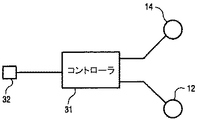
図3に示すように、制御システムは、HP排出抽気流れの弁16を起動する出力制御信号に基づいて弁12、14を同時に動作させるための制御信号、例えば、ガスタービン燃焼システムへの蒸気噴射(「出力増補」とも呼ばれる)を発生させるための抽気流れを制御する信号を送信するコントローラ31を含む。弁16の起動を、例えば、センサ32により感知し、それをコントローラ31に入力することができる。あるいは、図4に示すように、コントローラ31は、センサ42によりポイントCで感知されるHPボウル圧力と、センサ41によりポイントDで感知されるHP排気圧力との事前設定圧力比に従って弁12及び14へ制御信号を出力することができる。
As shown in FIG. 3, the control system includes a control signal for simultaneously operating the
次に、図1を参照して本発明のシステムの動作を説明する。HP排出抽気が弁16を開放することによりターンオンされると、HP排気圧力は低下し、HP段の両側の圧力比は増加する。同時に、HP段スラストは増加し、蒸気タービンの正味スラストはHP排気流れ方向に向かってシフトする。 Next, the operation of the system of the present invention will be described with reference to FIG. When the HP exhaust bleed is turned on by opening the valve 16, the HP exhaust pressure drops and the pressure ratio on both sides of the HP stage increases. At the same time, the HP stage thrust increases and the net thrust of the steam turbine shifts toward the HP exhaust flow direction.
増加した段スラストを相殺するために、スラスト制御システムは先に説明したように起動される。弁12が閉じる一方で、弁14は開き、それにより、N1パッキングリークオフ宛先ポイントはより高圧の段に切り替わる。これにより、N1パッキングロータステップにおけるステップ圧力は増加し、その結果、ステップスラストの値は増加する。そこで、増加した段スラストは直接に相殺され、これは総スラスト荷重変化の範囲を動作エンベロープ全体にわたり制限する方向に向かって作用する。
To offset the increased stage thrust, the thrust control system is activated as described above. While
この制御システムを実現するためには、N1パッキングロータステップ直径及び第2のN1パッキングリークオフ接続のための段圧力を慎重に選択しなければならない。HP排出抽気に対する要求が終了すると、弁12は開き、弁14は閉じる。
To implement this control system, the N1 packing rotor step diameter and the stage pressure for the second N1 packing leak-off connection must be carefully selected. When the request for HP exhaust bleed is complete,
図2に示すように、別の実施例は、図1に示す弁TCV1及びTCV2の機能を組み合わせた2方向偏向弁(TCV)21を使用する。 As shown in FIG. 2, another embodiment uses a two-way deflection valve (TCV) 21 that combines the functions of the valves TCV1 and TCV2 shown in FIG.
本発明を最も実用的で好ましい実施例であると現時点で考えられるものに関連して説明したが、本発明は開示された実施例に限定されず、また、特許請求の範囲に記載された符号は、理解容易のためであってなんら発明の技術的範囲を実施例に限縮するものではない。 Although the present invention has been described in connection with what is presently considered to be the most practical and preferred embodiment, the present invention is not limited to the disclosed embodiment, and is not limited to the claims. Is for the sake of easy understanding and does not limit the technical scope of the invention to the embodiments.
10…パイプ、12…弁(TCV1)、14…弁(TCV2)、16…弁(TCV)、21…2方向偏向弁、31…コントローラ、32、41、42…センサ 10 pipe, 12 valve (TCV1), 14 valve (TCV2), 16 valve (TCV), 21 two-way deflection valve, 31 controller, 32, 41, 42 sensor
Claims (12)
前記パッキングステップを前記中間圧力セクションの排気口の上流側における、より高圧の段に接続された第2の蒸気流路に選択的に接続する配管(10)と、
前記第1及び第2の蒸気流路の内部に配置され、制御信号(31)に応答して、前記中間圧力セクションの排気口から前記より高圧の段へ蒸気流路を変更する弁制御システム(12、14、16)とを具備する蒸気タービンシステム。 A single-flow high-pressure section and a single-flow intermediate-pressure section opposed thereto, a first steam flow path from a packing step at an outlet of the high-pressure section to an outlet of the intermediate-pressure section, and an outlet of the high-pressure section. A steam extraction system for extracting steam.
A pipe (10) for selectively connecting the packing step to a second steam flow path upstream of the outlet of the intermediate pressure section and connected to a higher pressure stage;
A valve control system disposed within the first and second steam flow paths and responsive to a control signal (31) for changing a steam flow path from an outlet of the intermediate pressure section to the higher pressure stage ( 12, 14, 16).
前記パッキングステップから前記中間圧力セクションの排気口の上流側の、より高圧の段に至る第2の蒸気流路を提供することと、
前記第1及び第2の蒸気流路の内部に配置された弁制御システムを動作させる制御信号(31)に応答して、蒸気流路を前記第1の蒸気流路から前記第2の蒸気流路へ偏向することから成る方法。 A large bleed flow at the outlet of the high pressure section of the steam turbine system further comprising at least one intermediate pressure section and a first steam flow path from a packing step of the outlet of the high pressure section to the outlet of the intermediate pressure section. Method to offset the thrust effect of
Providing a second steam flow path from the packing step to a higher pressure stage upstream of the outlet of the intermediate pressure section;
Responsive to a control signal (31) for operating a valve control system disposed within the first and second steam flow paths, the flow path from the first steam flow path to the second steam flow; A method comprising deflecting into a path.
Applications Claiming Priority (1)
| Application Number | Priority Date | Filing Date | Title |
|---|---|---|---|
| US10/310,858 US6705086B1 (en) | 2002-12-06 | 2002-12-06 | Active thrust control system for combined cycle steam turbines with large steam extraction |
Publications (3)
| Publication Number | Publication Date |
|---|---|
| JP2004190672A true JP2004190672A (en) | 2004-07-08 |
| JP2004190672A5 JP2004190672A5 (en) | 2007-01-25 |
| JP3989891B2 JP3989891B2 (en) | 2007-10-10 |
Family
ID=31946593
Family Applications (1)
| Application Number | Title | Priority Date | Filing Date |
|---|---|---|---|
| JP2003406754A Expired - Fee Related JP3989891B2 (en) | 2002-12-06 | 2003-12-05 | An active thrust control system for combined cycle steam turbines with mass extraction. |
Country Status (4)
| Country | Link |
|---|---|
| US (1) | US6705086B1 (en) |
| JP (1) | JP3989891B2 (en) |
| CN (1) | CN100398786C (en) |
| DE (1) | DE10356521B4 (en) |
Cited By (6)
| Publication number | Priority date | Publication date | Assignee | Title |
|---|---|---|---|---|
| KR20100074065A (en) * | 2008-12-23 | 2010-07-01 | 제너럴 일렉트릭 캄파니 | Opposed flow high pressure-low pressure steam turbine |
| JP2011179496A (en) * | 2010-03-02 | 2011-09-15 | General Electric Co <Ge> | Turbine system including valve for leak off line for controlling seal steam flow |
| WO2012002051A1 (en) * | 2010-06-30 | 2012-01-05 | 三菱重工業株式会社 | Vapour turbine and vapour turbine thrust adjustment method |
| JP2012007610A (en) * | 2010-06-23 | 2012-01-12 | General Electric Co <Ge> | System for controlling thrust in steam turbine |
| JP2012007609A (en) * | 2010-06-23 | 2012-01-12 | General Electric Co <Ge> | System for controlling thrust in steam turbine |
| JP2012122357A (en) * | 2010-12-06 | 2012-06-28 | Mitsubishi Heavy Ind Ltd | Steam turbine, power plant, and steam turbine operating method |
Families Citing this family (12)
| Publication number | Priority date | Publication date | Assignee | Title |
|---|---|---|---|---|
| US6892540B1 (en) | 2004-05-27 | 2005-05-17 | General Electric Company | System and method for controlling a steam turbine |
| US7195443B2 (en) | 2004-12-27 | 2007-03-27 | General Electric Company | Variable pressure-controlled cooling scheme and thrust control arrangements for a steam turbine |
| US8864442B2 (en) * | 2010-12-01 | 2014-10-21 | General Electric Company | Midspan packing pressure turbine diagnostic method |
| US9003799B2 (en) * | 2012-08-30 | 2015-04-14 | General Electric Company | Thermodynamic cycle optimization for a steam turbine cycle |
| US8863522B2 (en) * | 2012-10-16 | 2014-10-21 | General Electric Company | Operating steam turbine reheat section with overload valve |
| US9032733B2 (en) * | 2013-04-04 | 2015-05-19 | General Electric Company | Turbomachine system with direct header steam injection, related control system and program product |
| EP2987952A1 (en) * | 2014-08-20 | 2016-02-24 | Siemens Aktiengesellschaft | Steam turbine and method for operating a steam turbine |
| US10247029B2 (en) * | 2016-02-04 | 2019-04-02 | United Technologies Corporation | Method for clearance control in a gas turbine engine |
| JP6652662B2 (en) * | 2016-12-12 | 2020-02-26 | 東芝エネルギーシステムズ株式会社 | Turbine and turbine system |
| US10871072B2 (en) * | 2017-05-01 | 2020-12-22 | General Electric Company | Systems and methods for dynamic balancing of steam turbine rotor thrust |
| CN112627913B (en) * | 2020-12-01 | 2022-08-19 | 中国船舶重工集团公司第七0三研究所 | Radial flow turbine axial force self-adaptive control system |
| CN121205752B (en) * | 2025-11-26 | 2026-02-17 | 上海汇舸环保科技集团股份有限公司 | Supercritical organic Rankine cycle efficiency optimization method and system |
Family Cites Families (8)
| Publication number | Priority date | Publication date | Assignee | Title |
|---|---|---|---|---|
| US3604206A (en) * | 1968-07-31 | 1971-09-14 | Gen Electric | Shaft-sealing system for nuclear turbines |
| US3614255A (en) * | 1969-11-13 | 1971-10-19 | Gen Electric | Thrust balancing arrangement for steam turbine |
| US4819435A (en) * | 1988-07-11 | 1989-04-11 | Westinghouse Electric Corp. | Method for reducing valve loops for improving stream turbine efficiency |
| US5361585A (en) * | 1993-06-25 | 1994-11-08 | General Electric Company | Steam turbine split forward flow |
| US5660037A (en) * | 1995-06-27 | 1997-08-26 | Siemens Power Corporation | Method for conversion of a reheat steam turbine power plant to a non-reheat combined cycle power plant |
| JP3963479B2 (en) * | 1996-03-07 | 2007-08-22 | シーメンス アクチエンゲゼルシヤフト | Method and apparatus for rapid power regulation of power plant |
| US6443690B1 (en) * | 1999-05-05 | 2002-09-03 | Siemens Westinghouse Power Corporation | Steam cooling system for balance piston of a steam turbine and associated methods |
| DE19953123A1 (en) | 1999-11-04 | 2001-05-10 | Abb Alstom Power Ch Ag | Turbo assembly for steam power plant has high and mean pressure turbines on common shaft each with thrust compensating pistons where mean pressure piston is at outlet side on high pressure turbine to be fed direct with high pressure steam |
-
2002
- 2002-12-06 US US10/310,858 patent/US6705086B1/en not_active Expired - Lifetime
-
2003
- 2003-12-03 DE DE10356521.3A patent/DE10356521B4/en not_active Expired - Fee Related
- 2003-12-05 JP JP2003406754A patent/JP3989891B2/en not_active Expired - Fee Related
- 2003-12-05 CN CNB2003101231715A patent/CN100398786C/en not_active Expired - Fee Related
Cited By (10)
| Publication number | Priority date | Publication date | Assignee | Title |
|---|---|---|---|---|
| KR20100074065A (en) * | 2008-12-23 | 2010-07-01 | 제너럴 일렉트릭 캄파니 | Opposed flow high pressure-low pressure steam turbine |
| JP2010151130A (en) * | 2008-12-23 | 2010-07-08 | General Electric Co <Ge> | Counterflow high pressure-low pressure steam turbine |
| KR101665699B1 (en) * | 2008-12-23 | 2016-10-12 | 제너럴 일렉트릭 캄파니 | Opposed flow high pressure-low pressure steam turbine |
| JP2011179496A (en) * | 2010-03-02 | 2011-09-15 | General Electric Co <Ge> | Turbine system including valve for leak off line for controlling seal steam flow |
| JP2012007610A (en) * | 2010-06-23 | 2012-01-12 | General Electric Co <Ge> | System for controlling thrust in steam turbine |
| JP2012007609A (en) * | 2010-06-23 | 2012-01-12 | General Electric Co <Ge> | System for controlling thrust in steam turbine |
| WO2012002051A1 (en) * | 2010-06-30 | 2012-01-05 | 三菱重工業株式会社 | Vapour turbine and vapour turbine thrust adjustment method |
| KR101466457B1 (en) | 2010-06-30 | 2014-11-28 | 미츠비시 쥬고교 가부시키가이샤 | Vapour turbine and vapour turbine thrust adjustment method |
| JP2012122357A (en) * | 2010-12-06 | 2012-06-28 | Mitsubishi Heavy Ind Ltd | Steam turbine, power plant, and steam turbine operating method |
| US8857183B2 (en) | 2010-12-06 | 2014-10-14 | Mitsubishi Heavy Industries, Ltd. | Steam turbine, power plant and method for operating steam turbine |
Also Published As
| Publication number | Publication date |
|---|---|
| DE10356521B4 (en) | 2018-05-30 |
| CN1514113A (en) | 2004-07-21 |
| CN100398786C (en) | 2008-07-02 |
| DE10356521A1 (en) | 2004-07-01 |
| US6705086B1 (en) | 2004-03-16 |
| JP3989891B2 (en) | 2007-10-10 |
Similar Documents
| Publication | Publication Date | Title |
|---|---|---|
| JP3989891B2 (en) | An active thrust control system for combined cycle steam turbines with mass extraction. | |
| US20090136337A1 (en) | Method and Apparatus for Improved Reduced Load Operation of Steam Turbines | |
| US8863522B2 (en) | Operating steam turbine reheat section with overload valve | |
| JP5868008B2 (en) | Turbine system with a valve for leak off-line that controls the seal steam flow | |
| US5660037A (en) | Method for conversion of a reheat steam turbine power plant to a non-reheat combined cycle power plant | |
| JP5897274B2 (en) | Steam turbine flow control system | |
| JPS6240526B2 (en) | ||
| US20150330220A1 (en) | Method for balancing thrust, turbine and turbine engine | |
| JP7159205B2 (en) | System and method for dynamic balancing of steam turbine rotor thrust | |
| JP2006161698A (en) | Steam turbine overload operation apparatus and steam turbine overload operation method | |
| JP4183653B2 (en) | Thermal power plant and operation method | |
| JP2002115807A (en) | Operating method of driving turbine for boiler feed pump and operating device thereof | |
| JPH0953414A (en) | Turbine steam extraction control device | |
| JP5977504B2 (en) | Steam-driven power plant | |
| JP4341827B2 (en) | Exhaust gas passage configuration of combined cycle and its operation method | |
| JP2010255527A (en) | Combined cycle power generation system | |
| JPH0319884B2 (en) | ||
| EP1666699A1 (en) | Combined cycle power plant with gas and steam turbo groups | |
| JPH10196311A (en) | Heat Prevention Device for Steam Turbine Medium Pressure First Stage Blade Implantation Section | |
| JPS59113216A (en) | steam turbine plant | |
| JP2004027938A (en) | Multi-shaft combined cycle plant and control method thereof | |
| JPH11210409A (en) | Steam turbine plant | |
| JPH11343817A (en) | Combined power generation plant | |
| JPS58200007A (en) | Prevention of racing of steam turbine | |
| JPS6296702A (en) | Flow control device on group of master and slave valves |
Legal Events
| Date | Code | Title | Description |
|---|---|---|---|
| A521 | Written amendment |
Free format text: JAPANESE INTERMEDIATE CODE: A523 Effective date: 20061204 |
|
| A621 | Written request for application examination |
Free format text: JAPANESE INTERMEDIATE CODE: A621 Effective date: 20061204 |
|
| A871 | Explanation of circumstances concerning accelerated examination |
Free format text: JAPANESE INTERMEDIATE CODE: A871 Effective date: 20061204 |
|
| A975 | Report on accelerated examination |
Free format text: JAPANESE INTERMEDIATE CODE: A971005 Effective date: 20070129 |
|
| A131 | Notification of reasons for refusal |
Free format text: JAPANESE INTERMEDIATE CODE: A131 Effective date: 20070220 |
|
| A521 | Written amendment |
Free format text: JAPANESE INTERMEDIATE CODE: A523 Effective date: 20070516 |
|
| TRDD | Decision of grant or rejection written | ||
| A01 | Written decision to grant a patent or to grant a registration (utility model) |
Free format text: JAPANESE INTERMEDIATE CODE: A01 Effective date: 20070619 |
|
| A61 | First payment of annual fees (during grant procedure) |
Free format text: JAPANESE INTERMEDIATE CODE: A61 Effective date: 20070718 |
|
| FPAY | Renewal fee payment (event date is renewal date of database) |
Free format text: PAYMENT UNTIL: 20100727 Year of fee payment: 3 |
|
| R150 | Certificate of patent or registration of utility model |
Ref document number: 3989891 Country of ref document: JP Free format text: JAPANESE INTERMEDIATE CODE: R150 Free format text: JAPANESE INTERMEDIATE CODE: R150 |
|
| FPAY | Renewal fee payment (event date is renewal date of database) |
Free format text: PAYMENT UNTIL: 20110727 Year of fee payment: 4 |
|
| R250 | Receipt of annual fees |
Free format text: JAPANESE INTERMEDIATE CODE: R250 |
|
| FPAY | Renewal fee payment (event date is renewal date of database) |
Free format text: PAYMENT UNTIL: 20110727 Year of fee payment: 4 |
|
| FPAY | Renewal fee payment (event date is renewal date of database) |
Free format text: PAYMENT UNTIL: 20120727 Year of fee payment: 5 |
|
| R250 | Receipt of annual fees |
Free format text: JAPANESE INTERMEDIATE CODE: R250 |
|
| FPAY | Renewal fee payment (event date is renewal date of database) |
Free format text: PAYMENT UNTIL: 20120727 Year of fee payment: 5 |
|
| FPAY | Renewal fee payment (event date is renewal date of database) |
Free format text: PAYMENT UNTIL: 20130727 Year of fee payment: 6 |
|
| R250 | Receipt of annual fees |
Free format text: JAPANESE INTERMEDIATE CODE: R250 |
|
| R250 | Receipt of annual fees |
Free format text: JAPANESE INTERMEDIATE CODE: R250 |
|
| R250 | Receipt of annual fees |
Free format text: JAPANESE INTERMEDIATE CODE: R250 |
|
| R250 | Receipt of annual fees |
Free format text: JAPANESE INTERMEDIATE CODE: R250 |
|
| R250 | Receipt of annual fees |
Free format text: JAPANESE INTERMEDIATE CODE: R250 |
|
| R250 | Receipt of annual fees |
Free format text: JAPANESE INTERMEDIATE CODE: R250 |
|
| R250 | Receipt of annual fees |
Free format text: JAPANESE INTERMEDIATE CODE: R250 |
|
| R250 | Receipt of annual fees |
Free format text: JAPANESE INTERMEDIATE CODE: R250 |
|
| LAPS | Cancellation because of no payment of annual fees |