JP2004190672A - 大量抽気を伴う複合サイクル蒸気タービンの能動スラスト制御システム - Google Patents
大量抽気を伴う複合サイクル蒸気タービンの能動スラスト制御システム Download PDFInfo
- Publication number
- JP2004190672A JP2004190672A JP2003406754A JP2003406754A JP2004190672A JP 2004190672 A JP2004190672 A JP 2004190672A JP 2003406754 A JP2003406754 A JP 2003406754A JP 2003406754 A JP2003406754 A JP 2003406754A JP 2004190672 A JP2004190672 A JP 2004190672A
- Authority
- JP
- Japan
- Prior art keywords
- steam
- pressure section
- outlet
- valve
- flow path
- Prior art date
- Legal status (The legal status is an assumption and is not a legal conclusion. Google has not performed a legal analysis and makes no representation as to the accuracy of the status listed.)
- Granted
Links
Images



Classifications
-
- F—MECHANICAL ENGINEERING; LIGHTING; HEATING; WEAPONS; BLASTING
- F01—MACHINES OR ENGINES IN GENERAL; ENGINE PLANTS IN GENERAL; STEAM ENGINES
- F01D—NON-POSITIVE DISPLACEMENT MACHINES OR ENGINES, e.g. STEAM TURBINES
- F01D3/00—Machines or engines with axial-thrust balancing effected by working-fluid
- F01D3/04—Machines or engines with axial-thrust balancing effected by working-fluid axial thrust being compensated by thrust-balancing dummy piston or the like
-
- F—MECHANICAL ENGINEERING; LIGHTING; HEATING; WEAPONS; BLASTING
- F01—MACHINES OR ENGINES IN GENERAL; ENGINE PLANTS IN GENERAL; STEAM ENGINES
- F01D—NON-POSITIVE DISPLACEMENT MACHINES OR ENGINES, e.g. STEAM TURBINES
- F01D1/00—Non-positive-displacement machines or engines, e.g. steam turbines
- F01D1/02—Non-positive-displacement machines or engines, e.g. steam turbines with stationary working-fluid guiding means and bladed or like rotor, e.g. multi-bladed impulse steam turbines
- F01D1/023—Non-positive-displacement machines or engines, e.g. steam turbines with stationary working-fluid guiding means and bladed or like rotor, e.g. multi-bladed impulse steam turbines the working-fluid being divided into several separate flows ; several separate fluid flows being united in a single flow; the machine or engine having provision for two or more different possible fluid flow paths
-
- F—MECHANICAL ENGINEERING; LIGHTING; HEATING; WEAPONS; BLASTING
- F01—MACHINES OR ENGINES IN GENERAL; ENGINE PLANTS IN GENERAL; STEAM ENGINES
- F01D—NON-POSITIVE DISPLACEMENT MACHINES OR ENGINES, e.g. STEAM TURBINES
- F01D3/00—Machines or engines with axial-thrust balancing effected by working-fluid
-
- F—MECHANICAL ENGINEERING; LIGHTING; HEATING; WEAPONS; BLASTING
- F01—MACHINES OR ENGINES IN GENERAL; ENGINE PLANTS IN GENERAL; STEAM ENGINES
- F01D—NON-POSITIVE DISPLACEMENT MACHINES OR ENGINES, e.g. STEAM TURBINES
- F01D3/00—Machines or engines with axial-thrust balancing effected by working-fluid
- F01D3/02—Machines or engines with axial-thrust balancing effected by working-fluid characterised by having one fluid flow in one axial direction and another fluid flow in the opposite direction
-
- F—MECHANICAL ENGINEERING; LIGHTING; HEATING; WEAPONS; BLASTING
- F01—MACHINES OR ENGINES IN GENERAL; ENGINE PLANTS IN GENERAL; STEAM ENGINES
- F01K—STEAM ENGINE PLANTS; STEAM ACCUMULATORS; ENGINE PLANTS NOT OTHERWISE PROVIDED FOR; ENGINES USING SPECIAL WORKING FLUIDS OR CYCLES
- F01K23/00—Plants characterised by more than one engine delivering power external to the plant, the engines being driven by different fluids
- F01K23/02—Plants characterised by more than one engine delivering power external to the plant, the engines being driven by different fluids the engine cycles being thermally coupled
- F01K23/06—Plants characterised by more than one engine delivering power external to the plant, the engines being driven by different fluids the engine cycles being thermally coupled combustion heat from one cycle heating the fluid in another cycle
- F01K23/10—Plants characterised by more than one engine delivering power external to the plant, the engines being driven by different fluids the engine cycles being thermally coupled combustion heat from one cycle heating the fluid in another cycle with exhaust fluid of one cycle heating the fluid in another cycle
- F01K23/106—Plants characterised by more than one engine delivering power external to the plant, the engines being driven by different fluids the engine cycles being thermally coupled combustion heat from one cycle heating the fluid in another cycle with exhaust fluid of one cycle heating the fluid in another cycle with water evaporated or preheated at different pressures in exhaust boiler
-
- F—MECHANICAL ENGINEERING; LIGHTING; HEATING; WEAPONS; BLASTING
- F01—MACHINES OR ENGINES IN GENERAL; ENGINE PLANTS IN GENERAL; STEAM ENGINES
- F01K—STEAM ENGINE PLANTS; STEAM ACCUMULATORS; ENGINE PLANTS NOT OTHERWISE PROVIDED FOR; ENGINES USING SPECIAL WORKING FLUIDS OR CYCLES
- F01K7/00—Steam engine plants characterised by the use of specific types of engine; Plants or engines characterised by their use of special steam systems, cycles or processes; Control means specially adapted for such systems, cycles or processes; Use of withdrawn or exhaust steam for feed-water heating
- F01K7/34—Steam engine plants characterised by the use of specific types of engine; Plants or engines characterised by their use of special steam systems, cycles or processes; Control means specially adapted for such systems, cycles or processes; Use of withdrawn or exhaust steam for feed-water heating the engines being of extraction or non-condensing type; Use of steam for feed-water heating
- F01K7/345—Control or safety-means particular thereto
Landscapes
- Engineering & Computer Science (AREA)
- Mechanical Engineering (AREA)
- General Engineering & Computer Science (AREA)
- Chemical & Material Sciences (AREA)
- Combustion & Propulsion (AREA)
- Physics & Mathematics (AREA)
- Fluid Mechanics (AREA)
- Control Of Turbines (AREA)
- Turbine Rotor Nozzle Sealing (AREA)
Abstract
【解決手段】 プロセス抽気流れを形成するシステムを含む複合サイクル蒸気タービンは、蒸気タービンの高圧セクションの排気口における抽気流れのスラスト効果を相殺する制御システム(31)を含む。制御システム(31)は、HP排気パッキングリークオフ蒸気を蒸気タービンの中間圧力セクションの、より低圧の段からより高圧の段へ偏向させる弁(12、14、16)及び配管構造(10)を含む。
【選択図】 図3
Description
a) ガスタービンの出力を増補するためにガスタービン燃焼システムへの蒸気噴射を実行させ、
b) プロセス抽気を提供することを目的としている。
Claims (12)
- 単流高圧セクション及びそれに対向する単流中間圧力セクションと、前記高圧セクションの排気口にあるパッキングステップから前記中間圧力セクションの排気口に至る第1の蒸気流路と、前記高圧セクションの排気口から蒸気を抽出するプロセス抽気システムとを有する蒸気タービンシステムにおいて、
前記パッキングステップを前記中間圧力セクションの排気口の上流側における、より高圧の段に接続された第2の蒸気流路に選択的に接続する配管(10)と、
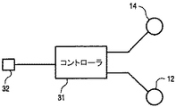
前記第1及び第2の蒸気流路の内部に配置され、制御信号(31)に応答して、前記中間圧力セクションの排気口から前記より高圧の段へ蒸気流路を変更する弁制御システム(12、14、16)とを具備する蒸気タービンシステム。 - 前記弁制御システム(12、14、16)は、前記第1の蒸気流路の内部に配置された第1の制御弁(12、14、16)と、前記第2の蒸気流路の内部に配置された第2の制御弁(12、14、16)とを具備する請求項1記載の蒸気タービンシステム。
- 前記弁制御システム(12、14、16)は、前記プロセス抽気システムが前記高圧セクションの排気口から蒸気を抽出するときに前記第1の制御弁(12、14、16)を閉鎖すると同時に、前記第2の制御弁(12、14、16)を開放する制御手段を更に具備する請求項2記載の蒸気タービンシステム。
- 前記制御手段(12、14、16)は、前記プロセス抽気システムの制御弁(12、14、16)が開放されたか否かを感知することにより、前記プロセス抽気システムが前記高圧セクションの排気口から蒸気を抽出する時点を判定する請求項3記載の蒸気タービンシステム。
- 前記制御手段(12、14、16)は、前記高圧セクションの入口と排気口における蒸気圧力比が所定の値を超えたことを判定することにより、前記プロセス抽気システムが前記高圧セクションの排気口から蒸気を抽出する時点を判定する請求項3記載の蒸気タービンシステム。
- 前記弁制御システム(12、14、16)は、前記第1及び第2の蒸気流路の内部に配置された2方向偏向制御弁(12、14、16)を具備する請求項1記載の蒸気タービンシステム。
- 前記弁制御システム(12、14、16)は、前記プロセス抽気システムが前記高圧セクションの排気口から蒸気を抽出するときに前記第1の蒸気流路を閉鎖し且つ前記第2の蒸気流路を開放するように前記2方向偏向制御弁(21)を動作する制御手段を更に具備する請求項6記載の蒸気タービンシステム。
- 前記制御手段(31)は、前記プロセス抽気システムの制御弁(12、14、16)が開放されたか否かを感知することにより、前記プロセス抽気システムが前記高圧セクションの排気口から蒸気を抽出する時点を判定する請求項7記載の蒸気タービンシステム。
- 前記制御手段(31)は、前記高圧セクションの入口と排気口の蒸気圧力比が所定の値を超えたことを判定することにより、前記プロセス抽気システムが前記高圧セクションの排気口から蒸気を抽出する時点を判定する請求項7記載の蒸気タービンシステム。
- 少なくとも1つの中間圧力セクションと、高圧セクションの排気口のパッキングステップから前記中間圧力セクションの排気口に至る第1の蒸気流路とを更に含む蒸気タービンシステムの前記高圧セクションの排気口における大きな抽気流れのスラスト効果を相殺する方法において、
前記パッキングステップから前記中間圧力セクションの排気口の上流側の、より高圧の段に至る第2の蒸気流路を提供することと、
前記第1及び第2の蒸気流路の内部に配置された弁制御システムを動作させる制御信号(31)に応答して、蒸気流路を前記第1の蒸気流路から前記第2の蒸気流路へ偏向することから成る方法。 - 前記偏向する過程は、前記第1の蒸気流路の内部に配置された第1の制御弁(12、14、16)が閉じ且つ前記第2の蒸気流路の内部に配置された第2の制御弁(12、14、16)が開くように前記弁制御システム(12、14、16)を動作させることを含む請求項10記載の方法。
- 前記弁制御システム(12、14、16)を動作させることは、前記プロセス抽気システムが前記高圧セクションの排気口から蒸気を抽出するときに前記第1の制御弁(12、14、16)を閉鎖し且つ前記第2の制御弁(12、14、16)を開放する制御手段を利用することを含む請求項11記載の方法。
Applications Claiming Priority (1)
| Application Number | Priority Date | Filing Date | Title |
|---|---|---|---|
| US10/310,858 US6705086B1 (en) | 2002-12-06 | 2002-12-06 | Active thrust control system for combined cycle steam turbines with large steam extraction |
Publications (3)
| Publication Number | Publication Date |
|---|---|
| JP2004190672A true JP2004190672A (ja) | 2004-07-08 |
| JP2004190672A5 JP2004190672A5 (ja) | 2007-01-25 |
| JP3989891B2 JP3989891B2 (ja) | 2007-10-10 |
Family
ID=31946593
Family Applications (1)
| Application Number | Title | Priority Date | Filing Date |
|---|---|---|---|
| JP2003406754A Expired - Fee Related JP3989891B2 (ja) | 2002-12-06 | 2003-12-05 | 大量抽気を伴う複合サイクル蒸気タービンの能動スラスト制御システム |
Country Status (4)
| Country | Link |
|---|---|
| US (1) | US6705086B1 (ja) |
| JP (1) | JP3989891B2 (ja) |
| CN (1) | CN100398786C (ja) |
| DE (1) | DE10356521B4 (ja) |
Cited By (6)
| Publication number | Priority date | Publication date | Assignee | Title |
|---|---|---|---|---|
| KR20100074065A (ko) * | 2008-12-23 | 2010-07-01 | 제너럴 일렉트릭 캄파니 | 대향 유동 고압-저압 증기 터빈 |
| JP2011179496A (ja) * | 2010-03-02 | 2011-09-15 | General Electric Co <Ge> | シール蒸気流を制御するリークオフライン用のバルブを備えたタービンシステム |
| WO2012002051A1 (ja) * | 2010-06-30 | 2012-01-05 | 三菱重工業株式会社 | 蒸気タービンおよび蒸気タービンのスラスト調整方法 |
| JP2012007609A (ja) * | 2010-06-23 | 2012-01-12 | General Electric Co <Ge> | 蒸気タービンにおけるスラスト制御システム |
| JP2012007610A (ja) * | 2010-06-23 | 2012-01-12 | General Electric Co <Ge> | 蒸気タービンにおけるスラスト制御システム |
| JP2012122357A (ja) * | 2010-12-06 | 2012-06-28 | Mitsubishi Heavy Ind Ltd | 蒸気タービン、発電所および蒸気タービンの運転方法 |
Families Citing this family (12)
| Publication number | Priority date | Publication date | Assignee | Title |
|---|---|---|---|---|
| US6892540B1 (en) | 2004-05-27 | 2005-05-17 | General Electric Company | System and method for controlling a steam turbine |
| US7195443B2 (en) * | 2004-12-27 | 2007-03-27 | General Electric Company | Variable pressure-controlled cooling scheme and thrust control arrangements for a steam turbine |
| US8864442B2 (en) * | 2010-12-01 | 2014-10-21 | General Electric Company | Midspan packing pressure turbine diagnostic method |
| US9003799B2 (en) * | 2012-08-30 | 2015-04-14 | General Electric Company | Thermodynamic cycle optimization for a steam turbine cycle |
| US8863522B2 (en) * | 2012-10-16 | 2014-10-21 | General Electric Company | Operating steam turbine reheat section with overload valve |
| US9032733B2 (en) * | 2013-04-04 | 2015-05-19 | General Electric Company | Turbomachine system with direct header steam injection, related control system and program product |
| EP2987952A1 (de) * | 2014-08-20 | 2016-02-24 | Siemens Aktiengesellschaft | Dampfturbine und Verfahren zum Betrieb einer Dampfturbine |
| US10247029B2 (en) * | 2016-02-04 | 2019-04-02 | United Technologies Corporation | Method for clearance control in a gas turbine engine |
| JP6652662B2 (ja) * | 2016-12-12 | 2020-02-26 | 東芝エネルギーシステムズ株式会社 | タービン及びタービンシステム |
| US10871072B2 (en) * | 2017-05-01 | 2020-12-22 | General Electric Company | Systems and methods for dynamic balancing of steam turbine rotor thrust |
| CN112627913B (zh) * | 2020-12-01 | 2022-08-19 | 中国船舶重工集团公司第七0三研究所 | 径流透平轴向力自适应调控系统 |
| CN121205752B (zh) * | 2025-11-26 | 2026-02-17 | 上海汇舸环保科技集团股份有限公司 | 超临界有机朗肯循环效率优化方法及系统 |
Family Cites Families (8)
| Publication number | Priority date | Publication date | Assignee | Title |
|---|---|---|---|---|
| US3604206A (en) * | 1968-07-31 | 1971-09-14 | Gen Electric | Shaft-sealing system for nuclear turbines |
| US3614255A (en) * | 1969-11-13 | 1971-10-19 | Gen Electric | Thrust balancing arrangement for steam turbine |
| US4819435A (en) * | 1988-07-11 | 1989-04-11 | Westinghouse Electric Corp. | Method for reducing valve loops for improving stream turbine efficiency |
| US5361585A (en) * | 1993-06-25 | 1994-11-08 | General Electric Company | Steam turbine split forward flow |
| US5660037A (en) * | 1995-06-27 | 1997-08-26 | Siemens Power Corporation | Method for conversion of a reheat steam turbine power plant to a non-reheat combined cycle power plant |
| JP3963479B2 (ja) * | 1996-03-07 | 2007-08-22 | シーメンス アクチエンゲゼルシヤフト | 発電所プラントの迅速な出力調節のための方法および装置 |
| US6443690B1 (en) * | 1999-05-05 | 2002-09-03 | Siemens Westinghouse Power Corporation | Steam cooling system for balance piston of a steam turbine and associated methods |
| DE19953123A1 (de) | 1999-11-04 | 2001-05-10 | Abb Alstom Power Ch Ag | Schubausgleich einer Turbogruppe |
-
2002
- 2002-12-06 US US10/310,858 patent/US6705086B1/en not_active Expired - Lifetime
-
2003
- 2003-12-03 DE DE10356521.3A patent/DE10356521B4/de not_active Expired - Fee Related
- 2003-12-05 JP JP2003406754A patent/JP3989891B2/ja not_active Expired - Fee Related
- 2003-12-05 CN CNB2003101231715A patent/CN100398786C/zh not_active Expired - Fee Related
Cited By (10)
| Publication number | Priority date | Publication date | Assignee | Title |
|---|---|---|---|---|
| KR20100074065A (ko) * | 2008-12-23 | 2010-07-01 | 제너럴 일렉트릭 캄파니 | 대향 유동 고압-저압 증기 터빈 |
| JP2010151130A (ja) * | 2008-12-23 | 2010-07-08 | General Electric Co <Ge> | 対向流高圧−低圧蒸気タービン |
| KR101665699B1 (ko) * | 2008-12-23 | 2016-10-12 | 제너럴 일렉트릭 캄파니 | 대향 유동 고압-저압 증기 터빈 |
| JP2011179496A (ja) * | 2010-03-02 | 2011-09-15 | General Electric Co <Ge> | シール蒸気流を制御するリークオフライン用のバルブを備えたタービンシステム |
| JP2012007609A (ja) * | 2010-06-23 | 2012-01-12 | General Electric Co <Ge> | 蒸気タービンにおけるスラスト制御システム |
| JP2012007610A (ja) * | 2010-06-23 | 2012-01-12 | General Electric Co <Ge> | 蒸気タービンにおけるスラスト制御システム |
| WO2012002051A1 (ja) * | 2010-06-30 | 2012-01-05 | 三菱重工業株式会社 | 蒸気タービンおよび蒸気タービンのスラスト調整方法 |
| KR101466457B1 (ko) | 2010-06-30 | 2014-11-28 | 미츠비시 쥬고교 가부시키가이샤 | 증기 터빈 및 증기 터빈의 스러스트 조정 방법 |
| JP2012122357A (ja) * | 2010-12-06 | 2012-06-28 | Mitsubishi Heavy Ind Ltd | 蒸気タービン、発電所および蒸気タービンの運転方法 |
| US8857183B2 (en) | 2010-12-06 | 2014-10-14 | Mitsubishi Heavy Industries, Ltd. | Steam turbine, power plant and method for operating steam turbine |
Also Published As
| Publication number | Publication date |
|---|---|
| US6705086B1 (en) | 2004-03-16 |
| DE10356521B4 (de) | 2018-05-30 |
| JP3989891B2 (ja) | 2007-10-10 |
| CN1514113A (zh) | 2004-07-21 |
| DE10356521A1 (de) | 2004-07-01 |
| CN100398786C (zh) | 2008-07-02 |
Similar Documents
| Publication | Publication Date | Title |
|---|---|---|
| JP2004190672A (ja) | 大量抽気を伴う複合サイクル蒸気タービンの能動スラスト制御システム | |
| US20090136337A1 (en) | Method and Apparatus for Improved Reduced Load Operation of Steam Turbines | |
| US8863522B2 (en) | Operating steam turbine reheat section with overload valve | |
| JP5868008B2 (ja) | シール蒸気流を制御するリークオフライン用のバルブを備えたタービンシステム | |
| US5660037A (en) | Method for conversion of a reheat steam turbine power plant to a non-reheat combined cycle power plant | |
| JP5897274B2 (ja) | 蒸気タービン流量調整システム | |
| US4628693A (en) | Casing for district heating turbine | |
| JPS6240526B2 (ja) | ||
| JP7159205B2 (ja) | 蒸気タービンロータ推力の動的バランスのためのシステムおよび方法 | |
| JP4509759B2 (ja) | 蒸気タービンの過負荷運転装置および蒸気タービンの過負荷運転方法 | |
| JP4183653B2 (ja) | 火力発電プラントおよび運転方法 | |
| JP2002115807A (ja) | ボイラ給水ポンプ用駆動タービン運転方法およびその運転装置 | |
| JPH0953414A (ja) | タービン抽気制御装置 | |
| JP5977504B2 (ja) | 蒸気駆動発電プラント | |
| JP4341827B2 (ja) | コンバインドサイクルの排ガス通路構成とその運用方法 | |
| JP2010255527A (ja) | コンバインドサイクル発電システム | |
| JPH0319884B2 (ja) | ||
| EP1666699A1 (en) | Combined cycle power plant with gas and steam turbo groups | |
| JPH10196311A (ja) | 蒸気タービンの中圧初段動翼植込部の加熱防止装置 | |
| JPS59113216A (ja) | 蒸気タ−ビンプラント | |
| JP2004027938A (ja) | 多軸型コンバインドサイクルプラント及びその制御方法 | |
| JPH11343817A (ja) | コンバインド発電プラント | |
| JPS58200007A (ja) | 蒸気タ−ビンの空転防止方法 | |
| JPS6296702A (ja) | 親子弁群式流量加減装置 | |
| JPH11343816A (ja) | 複合発電プラント |
Legal Events
| Date | Code | Title | Description |
|---|---|---|---|
| A521 | Written amendment |
Free format text: JAPANESE INTERMEDIATE CODE: A523 Effective date: 20061204 |
|
| A621 | Written request for application examination |
Free format text: JAPANESE INTERMEDIATE CODE: A621 Effective date: 20061204 |
|
| A871 | Explanation of circumstances concerning accelerated examination |
Free format text: JAPANESE INTERMEDIATE CODE: A871 Effective date: 20061204 |
|
| A975 | Report on accelerated examination |
Free format text: JAPANESE INTERMEDIATE CODE: A971005 Effective date: 20070129 |
|
| A131 | Notification of reasons for refusal |
Free format text: JAPANESE INTERMEDIATE CODE: A131 Effective date: 20070220 |
|
| A521 | Written amendment |
Free format text: JAPANESE INTERMEDIATE CODE: A523 Effective date: 20070516 |
|
| TRDD | Decision of grant or rejection written | ||
| A01 | Written decision to grant a patent or to grant a registration (utility model) |
Free format text: JAPANESE INTERMEDIATE CODE: A01 Effective date: 20070619 |
|
| A61 | First payment of annual fees (during grant procedure) |
Free format text: JAPANESE INTERMEDIATE CODE: A61 Effective date: 20070718 |
|
| FPAY | Renewal fee payment (event date is renewal date of database) |
Free format text: PAYMENT UNTIL: 20100727 Year of fee payment: 3 |
|
| R150 | Certificate of patent or registration of utility model |
Ref document number: 3989891 Country of ref document: JP Free format text: JAPANESE INTERMEDIATE CODE: R150 Free format text: JAPANESE INTERMEDIATE CODE: R150 |
|
| FPAY | Renewal fee payment (event date is renewal date of database) |
Free format text: PAYMENT UNTIL: 20110727 Year of fee payment: 4 |
|
| R250 | Receipt of annual fees |
Free format text: JAPANESE INTERMEDIATE CODE: R250 |
|
| FPAY | Renewal fee payment (event date is renewal date of database) |
Free format text: PAYMENT UNTIL: 20110727 Year of fee payment: 4 |
|
| FPAY | Renewal fee payment (event date is renewal date of database) |
Free format text: PAYMENT UNTIL: 20120727 Year of fee payment: 5 |
|
| R250 | Receipt of annual fees |
Free format text: JAPANESE INTERMEDIATE CODE: R250 |
|
| FPAY | Renewal fee payment (event date is renewal date of database) |
Free format text: PAYMENT UNTIL: 20120727 Year of fee payment: 5 |
|
| FPAY | Renewal fee payment (event date is renewal date of database) |
Free format text: PAYMENT UNTIL: 20130727 Year of fee payment: 6 |
|
| R250 | Receipt of annual fees |
Free format text: JAPANESE INTERMEDIATE CODE: R250 |
|
| R250 | Receipt of annual fees |
Free format text: JAPANESE INTERMEDIATE CODE: R250 |
|
| R250 | Receipt of annual fees |
Free format text: JAPANESE INTERMEDIATE CODE: R250 |
|
| R250 | Receipt of annual fees |
Free format text: JAPANESE INTERMEDIATE CODE: R250 |
|
| R250 | Receipt of annual fees |
Free format text: JAPANESE INTERMEDIATE CODE: R250 |
|
| R250 | Receipt of annual fees |
Free format text: JAPANESE INTERMEDIATE CODE: R250 |
|
| R250 | Receipt of annual fees |
Free format text: JAPANESE INTERMEDIATE CODE: R250 |
|
| R250 | Receipt of annual fees |
Free format text: JAPANESE INTERMEDIATE CODE: R250 |
|
| LAPS | Cancellation because of no payment of annual fees |