JP2004190815A - Piping support structure and support method - Google Patents
Piping support structure and support method Download PDFInfo
- Publication number
- JP2004190815A JP2004190815A JP2002361424A JP2002361424A JP2004190815A JP 2004190815 A JP2004190815 A JP 2004190815A JP 2002361424 A JP2002361424 A JP 2002361424A JP 2002361424 A JP2002361424 A JP 2002361424A JP 2004190815 A JP2004190815 A JP 2004190815A
- Authority
- JP
- Japan
- Prior art keywords
- bolt
- pipe
- leg
- bolt hole
- mounting member
- Prior art date
- Legal status (The legal status is an assumption and is not a legal conclusion. Google has not performed a legal analysis and makes no representation as to the accuracy of the status listed.)
- Pending
Links
Images
Landscapes
- Supports For Pipes And Cables (AREA)
Abstract
【課題】配管を支持するUボルトに持続的な高サイクルの振動等が加わる場合に、該Uボルトの損傷を効果的に防止する。
【構成】配管1を支持したUボルト4の脚部5を取付部材2に設けたボルト孔3に挿通し、脚部5に形成されているネジ部6の後端6aがボルト孔3から配管1側に突出しない状態で、Uボルト4をナット7で締結する。
【選択図】 図1An object of the present invention is to effectively prevent damage to a U-bolt when a continuous high-cycle vibration or the like is applied to the U-bolt supporting a pipe.
[Structure] A leg 5 of a U-bolt 4 supporting a pipe 1 is inserted into a bolt hole 3 provided in a mounting member 2, and a rear end 6a of a screw portion 6 formed in the leg 5 is piped from the bolt hole 3. The U bolt 4 is fastened with the nut 7 without projecting to the one side.
[Selection diagram] Fig. 1
Description
【0001】
【発明の属する技術分野】
本発明はUボルトを利用した配管の支持構造および支持方法に関し、詳しくは、Uボルトが持続的な高サイクルの振動または持続的なせん断応力を受ける状況にある場合に好適に適用できる配管の支持構造および支持方法に関する。
【0002】
【従来の技術】
種々のプラントや施設では多くの配管が敷設されるが、通常、これら配管は建物の壁や構造躯体などの取付部材にUボルトを利用して支持される。すなわち配管を支持したUボルトの脚部を取付部材に形成したボルト孔に挿通し、一対の脚部に形成したネジ部にそれぞれナットを締結することにより配管を支持する。
【0003】
配管をUボルトで支持する場合の基準はJISで規定されている。例えば「船用鋼管取付Uボルト」についてはJIS F3022に定められ、Uボルトに対するナットの取付け方としてA形,B形,C形の3種が規定されている。ここでA形とB形は通常呼び寸法100mm以上、C形は通常呼び寸法90mm以下に適用される。
【0004】
A形は取付部材のボルト孔にUボルトの脚部を挿通し、ボルト孔を挟んで配管側と反対側の両方から脚部をナットで締結する方式であり、B形は取付部材のボルト孔にUボルトの脚部を挿通し、配管側と反対側から脚部を単一のナットで締結する方式であり、C形は取付部材のボルト孔にUボルトの脚部を挿通し、配管側と反対側から脚部をダブルナットで締結する方式である。そして特に振動の激しい場所ではC形を使用してもよいと規定している。
【0005】
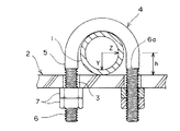
図2はJIS F3022に規定されたC形による配管の支持構造を示す断面図である。図2において、1は配管、2は取付部材、3は取付部材に設けたボルト孔、4はUボルト、5はUボルト4の脚部、6は脚部5に設けたネジ部、6aはネジ部の後端、7はナットである。図示のように配管1を取付部材2に支持するには、先ずUボルト4のU形部分で配管1を把持して支持し、その脚部5を取付部材2のボルト孔3に挿通した上で、配管1と反対側から脚部5に形成したネジ部6にナット7を二重に締結する。
【0006】
【発明が解決しようとする課題】
しかし図2に示す配管の支持構造では、脚部5に形成したネジ部6の後端6aが取付部材2のボルト穴3から配管側に突出している。そのためUボルト4が配管1から持続的な高サイクルの振動または持続的なせん断応力を受ける状況にある場合には、金属疲労によりUボルト4が損傷する恐れがある。
【0007】
実験によれば、Uボルトが配管1から図2に矢印で示すようなY方向およびZ方向の持続的な高サイクルの振動または持続的なせん断応力を受けると、Uボルトの脚部5に引張り荷重とせん断荷重が繰り返し作用し、それらは脚部5がボルト孔3の配管側の縁部と接触する部分に集中することが確認された。
【0008】
このように応力が集中する該部分は、前記のようにネジ部6が形成されているので、脚部の軸径が減少し切り込み効果も加わって損傷しやすくなるものと推定される。そこで本発明は従来のUボルトによる配管の支持構造における上記問題を解決することを課題とし、そのための新しい配管の支持構造および支持方法を提供することを目的とする。
【0009】
【課題を解決するための手段】
前記課題を解決する本発明に係る配管の支持構造は、配管を支持したUボルトの脚部が取付部材に設けたボルト孔に挿通され、前記Uボルトはその脚部に形成されたネジ部の後端がボルト孔から配管側に突出しない状態でナットにより締結されていることを特徴とする(請求項1)。
【0010】
上記支持構造によれば、Uボルトに形成したネジ部の後端がナット締結時にボルト孔から配管側に突出しないようになされている。そのため脚部がボルト孔の配管側の縁部と接触する部分には脚部の径を減少させるネジ部が存在しないので脚部の耐久性を向上させることができる。
【0011】
上記配管の支持構造はUボルトが配管から持続的な高サイクルの振動または持続的なせん断応力を受ける状況にある場合に、特に前記効果が発揮される(請求項2)。
なお、ここで高サイクルの振動とは、各種プラントの運転中に回転機械の回転や流体の流通に伴う振動により連続して発生する振動による疲労をいう。
【0012】
また、前記課題を解決する本発明に係る配管の支持方法は、配管を支持したUボルトの脚部を取付部材に設けたボルト孔に挿通し、脚部に形成したネジ部の後端がボルト孔から配管側に突出しないようにして、前記Uボルトの脚部にナットを締結することを特徴とする(請求項3)。
【0013】
上記配管の支持方法において、前記Uボルトをナットで締結する際にロックナットを介在することにより、脚部のボルト孔に対する挿通量を調整することができる(請求項4)。このようなロックナットを用いると、脚部のボルト孔に対する挿通量を任意に且つ容易に設定できる。
【0014】
【発明の実施の形態】
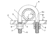
次に本発明の実施の形態を図面により説明する。図1は本発明に係る配管の支持構造を示す断面図である。図1において、1は配管、2は取付部材、3は取付部材にボルト孔、4はUボルト、5はUボルト4の脚部、6は脚部5に設けたネジ部、6aはネジ部の後端、7はナットである。
【0015】
図1の支持構造では、脚部5に形成したネジ部6がボルト孔3の内部から配管1と反対側に延長した状態とされているので、ネジ部6の後端6aはボルト孔3から配管1側に突出しない。そのため前記のように配管1から脚部5に加わる荷重はネジ部6を形成していない部分に集中することになり、脚部5の耐久性を向上させることができる。
【0016】
すなわち、配管1からUボルト4が図1に矢印で示すようなY方向およびZ方向の持続的な高サイクルの振動または持続的なせん断応力を受けた場合、それによってUボルト4の脚部5に引張り荷重とせん断荷重が作用し、それらは脚部5がボルト孔3の配管1側の縁部と接触する部分に集中する。しかし該接触部分にはネジ部6が形成されていないので、脚部5の実質断面積は本来の断面積のままであるから耐荷重性が低下することはなく、結果として脚部5の耐久性が向上する。
【0017】
図示のように配管1を取付部材2に支持するには、先ず配管1を支持したUボルト4の脚部5を取付部材2に設けたボルト孔3に挿通し、脚部5に形成したネジ部6の後端6aがボルト孔3から配管側に突出しないようにして、前記Uボルト4の脚部5にナット7を締結する。
脚部5にナット7を締結する際に、平座金及びばね座金等からなるスペーサまたはロックナット8を1枚もしくは数枚介在させることにより、脚部5のボルト孔3に対する挿通量を任意に且つ容易に設定することができる。
【0018】
【実施例】
次に図1に示す本発明に係る配管の支持構造におけるUボルトの強度についての実験例を説明する。配管1の口径Dが34mm、取付部材2から配管1の中心までの高さhがD/2=17mm、配管1からUボルトに加わるZ方向の反力Rzが48.0Kg、Y方向の反力Ryが76.3Kg、Z方向の加振力(解析値)Fzが28.0Kg、Y方向の加振力(解析値)Fyが35.0Kgであるとき、Uボルト4における曲げモーメントや応力度は次のように計算される。
【0019】
(1)配管反力による応力
Uボルトの曲げモーメントM=Rz×h=48.0×17=816.0(Kg・mm)
Uボルトの曲げ応力度σb=M/Z=816.0/98.18=8.31(Kg/mm2 )
但し、上記式中のZはボルト断面係数であり、ボルトの軸径d2を10mmとするとZ=(π×d2の3乗)/32=(π×10の3乗)/32=98.18(mm3 )となる。
【0020】
Uボルトの引張力T=Ry/2=76.3/2=38.15(Kg)
Uボルトの引張応力度σt=βk×(T/A1)=2.64×(38.15/55.1)=1.83(Kg/mm2 )
但し、上記式中のA1はネジ部におけるUボルトの断面積であり、ボルト谷径d1を8.376mmとすると、A1=π×(d1の2乗/4)=π×(8.376の2条/4)=55.1(mm2 )となる。
【0021】
Uボルトのせん断応力度τ=Rz/A2=48.0/78.54=0.61(Kg/mm2 )
但し、上記式中のA2はUボルトの断面積であり、軸径d2を10mmとすると、A2=π×(d2の2乗)/4=π×(10の2乗)/4=78.54(mm)となる。
合成応力度σm=[(σb+σt)の2乗+3×τの2乗]=10.19(Kg/mm2 )
【0022】
(2)振動時の応力振幅
Uボルトの曲げモーメントM=Fz×h=28.0×17=476.0(Kg・mm)
Uボルトの曲げ応力度度σb=M/Z=476.0/598.18=4.85(Kg/mm2 )
Uボルトの引張力T=Fy/2=35.0/2=17.5(Kg)
【0023】
Uボルトの引張応力度σt=βk×(T/A1)=2.64×(17.5/55.1)=0.84(Kg/mm2 )
Uボルトのせん断応力度τ=Fz/A2=28.0/78.54=0.36(Kg/mm2 )
合成応力度σm=[(σb+σt)の2乗+3×τの2乗]=5.72(Kg/mm2 )
【0024】
上記各式において、応力度はUボルトが単位断面積当たりに受ける応力であるから、この値が小さいほど耐久性がよいことになる。
次に比較のため図2に示す従来の配管の支持構造について、図1と同じ配管からの配管反力や振動加振力が加わったときのUボルトにおける曲げモーメントや応力度は次のように計算される。
【0025】
(1)管反力による応力
Uボルトの曲げモーメントM=Rz×h=48.0×17=816.0(Kg・mm)
Uボルトの曲げ応力度σb=M/Z=816.0/57.7=14.14(Kg/mm2 )
但し、上記式中のZはボルト断面係数であり、ボルト谷径d1を8.376mmとすると、Z=(π×d1の3乗)/32=(π×8.376の3乗)/32=57.7(mm3 )となる。
【0026】
Uボルトの引張力T=Ry/2=76.3/2=38.15(Kg)
Uボルトの引張応力度σt=βk×(T/A1)=2.64×(38.15/55.1)=1.83(Kg/mm2 )
但し、上記式中のA1はネジ部におけるUボルトの断面積であり、ボルト谷径d1を8.376mmすると、A1=π×(dの2乗/4)=π×(8.376の2条/4)=55.1(mm2 )となる。
Uボルトのせん断応力度τ=Rz/A1=48.0/55.1=0.87(Kg/mm2 )
合成応力度σm=[(σb+σt)の2乗+3×τの2乗]=16.04(Kg/mm2 )
【0027】
(2)振動時の応力振幅
Uボルトの曲げモーメントM=Fz×h=28.0×17=476.0(Kg・mm)
Uボルトの曲げ応力度度σb=M/Z=476.0/57.7=8.25(Kg/mm2 )
Uボルトの引張力T=Fy/2=35.0/2=17.5(Kg)
【0028】
Uボルトの引張応力度σt=βk×(T/A1)=2.64×(17.5/55.1)=0.84(Kg/mm2 )
Uボルトのせん断応力度τ=Fz/A1=28.0/55.1=0.51(Kg/mm2 )
合成応力度σm=[(σb+σt)の2乗+3×τの2乗]=9.13(Kg/mm2 )
【0029】
以上の実験結果から、図1に示す本発明に係る支持構造と、図2に示す従来の支持構造を比較すると、配管反力に対するUボルトの曲げ応力度σbは8.31/14.14=0.59(59%)、Uボルトのせん断応力度τは0.61/0.87=0.7(70%)、合成応力度は10.19/16.04=0.63(63%)に減少する。
【0030】
また振動時におけるUボルトの曲げ応力度σbは4.85/8.25=0.59(59%)、Uボルトのせん断応力度τは0.36/0.51=0.7(70%)、合成応力度は5.72/9.13=0.63(63%)に減少する。したがって、本発明に係る支持構造は時の支持構造に比べてUボルトを金属疲労させる応力度が減少するので、耐久性が向上することは明らかである。
【0031】
【発明の効果】
以上のように本発明に係る配管の支持構造は、配管を支持したUボルトの脚部が取付部材に設けたボルト孔に挿通され、前記Uボルトはその脚部に形成したネジ部の後端がボルト孔から配管側に突出しない状態でナットにより締結されていることを特徴とする。
【0032】
本支持構造によれば、Uボルトに形成したネジ部の後端がボルト孔から配管側に突出しないので、脚部がボルト孔の配管側の縁部と接触する部分には脚部の径を減少させるネジ部が形成されていない。そのため配管から脚部に加わる荷重はネジ部を形成していない部分に集中することになり、脚部の耐久性を向上させることができる。そして本支持構造は、Uボルトが配管から持続的な高サイクルの振動または持続的なせん断応力を受ける状況にある場合に、特に前記効果が発揮される。
【図面の簡単な説明】
【図1】本発明に係る配管の支持構造の断面図。
【図2】従来の配管の支持構造の断面図。
【符号の説明】
1 配管
2 取付部材
3 ボルト孔
4 Uボルト
5 脚部
6 ネジ部
6a 後端
7 ナット
8 ロックナット[0001]
TECHNICAL FIELD OF THE INVENTION
The present invention relates to a pipe supporting structure and a supporting method using a U-bolt, and more particularly, to a pipe supporting method that can be suitably applied when the U-bolt is subjected to a continuous high-cycle vibration or a continuous shear stress. It relates to the structure and the supporting method.
[0002]
[Prior art]
Many pipes are laid in various plants and facilities. Usually, these pipes are supported on mounting members such as building walls and structural frames using U-bolts. In other words, the pipe is supported by inserting the legs of the U-bolt supporting the pipe into the bolt holes formed in the mounting member and fastening nuts to the threaded portions formed on the pair of legs.
[0003]
Standards for supporting pipes with U bolts are specified in JIS. For example, “U-bolt for mounting steel pipes for ships” is specified in JIS F3022, and three types of A-type, B-type, and C-type are specified as a method of mounting a nut to the U-bolt. Here, the A type and the B type are applied to a nominal size of 100 mm or more, and the C type is applied to a nominal size of 90 mm or less.
[0004]
Type A is a method in which the leg of a U-bolt is inserted into the bolt hole of the mounting member, and the leg is fastened with nuts from both the piping side and the opposite side with the bolt hole in between. The U-bolt is inserted into the bolt hole of the mounting member, and the U-bolt is inserted into the bolt hole of the mounting member. And the legs are fastened with double nuts from the opposite side. In addition, it stipulates that a C-shape may be used especially in a place where vibration is severe.
[0005]
FIG. 2 is a cross-sectional view showing a C-shaped pipe support structure defined in JIS F3022. In FIG. 2, 1 is a pipe, 2 is a mounting member, 3 is a bolt hole provided on the mounting member, 4 is a U-bolt, 5 is a leg of the
[0006]
[Problems to be solved by the invention]
However, in the piping support structure shown in FIG. 2, the
[0007]
Experiments have shown that when a U-bolt is subjected to sustained high-cycle vibrations or sustained shear stress in the Y and Z directions as shown by the arrows in FIG. It was confirmed that a load and a shear load were repeatedly applied, and they were concentrated on a portion where the
[0008]
Since the
[0009]
[Means for Solving the Problems]
The pipe supporting structure according to the present invention that solves the above-mentioned problem has a U-bolt leg supporting a pipe inserted into a bolt hole provided in a mounting member, and the U-bolt having a threaded portion formed in the leg. The rear end is fastened by a nut without protruding from the bolt hole to the pipe side (claim 1).
[0010]
According to the above support structure, the rear end of the threaded portion formed on the U bolt is prevented from protruding from the bolt hole toward the pipe when the nut is fastened. Therefore, since there is no threaded portion for reducing the diameter of the leg at the portion where the leg contacts the edge of the bolt hole on the pipe side, the durability of the leg can be improved.
[0011]
The above-mentioned effect is exhibited particularly when the U-bolt is in a situation where the U-bolt receives a continuous high-cycle vibration or a continuous shear stress from the pipeline (claim 2).
Here, high-cycle vibration means fatigue caused by continuous vibration caused by rotation of a rotating machine or vibration caused by fluid flow during operation of various plants.
[0012]
In addition, a pipe supporting method according to the present invention for solving the above-mentioned problems is characterized in that a leg of a U-bolt supporting a pipe is inserted into a bolt hole provided in a mounting member, and a rear end of a screw part formed in the leg is bolted. A nut is fastened to the leg of the U-bolt so as not to protrude from the hole toward the pipe (claim 3).
[0013]
In the pipe supporting method, the amount of the leg portion inserted into the bolt hole can be adjusted by interposing the lock nut when the U bolt is fastened with the nut (claim 4). By using such a lock nut, the insertion amount of the leg portion into the bolt hole can be set arbitrarily and easily.
[0014]
BEST MODE FOR CARRYING OUT THE INVENTION
Next, an embodiment of the present invention will be described with reference to the drawings. FIG. 1 is a cross-sectional view showing a pipe support structure according to the present invention. In FIG. 1, 1 is a pipe, 2 is a mounting member, 3 is a bolt hole in the mounting member, 4 is a U-bolt, 5 is a leg of the
[0015]
In the support structure of FIG. 1, the
[0016]
That is, if the
[0017]
As shown in the figure, in order to support the pipe 1 on the mounting
When fastening the
[0018]
【Example】
Next, an experimental example on the strength of the U bolt in the pipe support structure according to the present invention shown in FIG. 1 will be described. The diameter D of the pipe 1 is 34 mm, the height h from the mounting
[0019]
(1) Bending moment of stress U bolt due to pipe reaction force M = Rz × h = 48.0 × 17 = 816.0 (Kg · mm)
U bolt bending stress degree σb = M / Z = 816.0 / 98.18 = 8.31 (Kg / mm 2 )
Here, Z in the above equation is a bolt section modulus, and when the shaft diameter d2 of the bolt is 10 mm, Z = (π × d2 cube) / 32 = (π × 10 cube) /32=98.18 (Mm 3 ).
[0020]
U bolt tension T = Ry / 2 = 76.3 / 2 = 38.15 (Kg)
U bolt tensile stress degree σt = βk × (T / A1) = 2.64 × (38.15 / 55.1) = 1.83 (Kg / mm 2 )
Here, A1 in the above equation is the cross-sectional area of the U bolt in the threaded portion, and when the bolt root diameter d1 is 8.376 mm, A1 = π × (square of d1 / 4) = π × (8.376 (2/4) = 55.1 (mm 2 ).
[0021]
U bolt shear stress τ = Rz / A2 = 48.0 / 78.54 = 0.61 (Kg / mm 2 )
Here, A2 in the above equation is the cross-sectional area of the U bolt, and when the shaft diameter d2 is 10 mm, A2 = π × (square of d2) / 4 = π × (square of 10) / 4 = 78. 54 (mm).
Synthetic stress degree σm = [square of (σb + σt) + square of 3 × τ] = 10.19 (Kg / mm 2 )
[0022]
(2) Stress amplitude during vibration U bending moment of bolt M = Fz × h = 28.0 × 17 = 476.0 (Kg · mm)
U bolt bending stress degree σb = M / Z = 476.0 / 598.18 = 4.85 (Kg / mm 2 )
U bolt tension T = Fy / 2 = 35.0 / 2 = 17.5 (Kg)
[0023]
U bolt tensile stress degree σt = βk × (T / A1) = 2.64 × (17.5 / 55.1) = 0.84 (Kg / mm 2 )
U bolt shear stress τ = Fz / A2 = 28.0 / 78.54 = 0.36 (Kg / mm 2 )
Synthetic stress degree σm = [square of (σb + σt) + square of 3 × τ] = 5.72 (Kg / mm 2 )
[0024]
In each of the above equations, the stress level is the stress that the U bolt receives per unit cross-sectional area, so that the smaller the value, the better the durability.
Next, for comparison, with respect to the conventional pipe support structure shown in FIG. 2, the bending moment and the stress degree in the U bolt when the pipe reaction force and the vibration excitation force from the same pipe as in FIG. 1 are applied are as follows. Is calculated.
[0025]
(1) Stress due to pipe reaction force U Bending moment of bolt M = Rz × h = 48.0 × 17 = 816.0 (Kg · mm)
U bolt bending stress degree σb = M / Z = 816.0 / 57.7 = 14.14 (Kg / mm 2 )
Here, Z in the above equation is a bolt section coefficient, and when the bolt root diameter d1 is 8.376 mm, Z = (π × d1 cube) / 32 = (π × 8.376 cube) / 32 = 57.7 (mm 3 ).
[0026]
U bolt tension T = Ry / 2 = 76.3 / 2 = 38.15 (Kg)
U bolt tensile stress degree σt = βk × (T / A1) = 2.64 × (38.15 / 55.1) = 1.83 (Kg / mm 2 )
Here, A1 in the above equation is the cross-sectional area of the U bolt in the threaded portion. If the bolt root diameter d1 is 8.376 mm, A1 = π × (square of d / 4) = π × (8.376 / 2) (Article / 4 ) = 55.1 (mm 2 ).
U bolt shear stress τ = Rz / A1 = 48.0 / 55.1 = 0.87 (Kg / mm 2 )
Synthetic stress degree σm = [square of (σb + σt) + square of 3 × τ] = 16.04 (Kg / mm 2 )
[0027]
(2) Stress amplitude during vibration U Bending moment of bolt M = Fz × h = 28.0 × 17 = 476.0 (Kg · mm)
U bolt bending stress degree σb = M / Z = 476.0 / 57.7 = 8.25 (Kg / mm 2 )
U bolt tension T = Fy / 2 = 35.0 / 2 = 17.5 (Kg)
[0028]
U bolt tensile stress degree σt = βk × (T / A1) = 2.64 × (17.5 / 55.1) = 0.84 (Kg / mm 2 )
U bolt shear stress τ = Fz / A1 = 28.0 / 55.1 = 0.51 (Kg / mm 2 )
Synthetic stress degree σm = [square of (σb + σt) + square of 3 × τ] = 9.13 (Kg / mm 2 )
[0029]
From the above experimental results, when the support structure according to the present invention shown in FIG. 1 is compared with the conventional support structure shown in FIG. 2, the bending stress degree σb of the U bolt with respect to the pipe reaction force is 8.31 / 14.14 = 0.59 (59%), the shear stress degree τ of the U bolt is 0.61 / 0.87 = 0.7 (70%), and the combined stress degree is 10.19 / 16.04 = 0.63 (63% ).
[0030]
The bending stress σb of the U bolt at the time of vibration is 4.85 / 8.25 = 0.59 (59%), and the shear stress τ of the U bolt is 0.36 / 0.51 = 0.7 (70% ), The resultant stress level is reduced to 5.72 / 9.13 = 0.63 (63%). Therefore, it is clear that the support structure according to the present invention has improved durability since the stress level that causes metal fatigue of the U-bolt is reduced as compared with the conventional support structure.
[0031]
【The invention's effect】
As described above, in the piping support structure according to the present invention, the legs of the U-bolt supporting the piping are inserted into the bolt holes provided in the mounting member, and the U-bolt is the rear end of the threaded portion formed in the leg. Are fastened by nuts without projecting from the bolt holes to the pipe side.
[0032]
According to the present support structure, the rear end of the threaded portion formed on the U bolt does not protrude from the bolt hole toward the pipe side. No threads to reduce are formed. Therefore, the load applied to the leg from the pipe concentrates on the portion where the thread is not formed, and the durability of the leg can be improved. The present support structure is particularly effective when the U-bolt is subjected to continuous high-cycle vibration or continuous shear stress from the pipe.
[Brief description of the drawings]
FIG. 1 is a sectional view of a pipe support structure according to the present invention.
FIG. 2 is a sectional view of a conventional pipe support structure.
[Explanation of symbols]
DESCRIPTION OF SYMBOLS 1
Claims (4)
Priority Applications (1)
| Application Number | Priority Date | Filing Date | Title |
|---|---|---|---|
| JP2002361424A JP2004190815A (en) | 2002-12-12 | 2002-12-12 | Piping support structure and support method |
Applications Claiming Priority (1)
| Application Number | Priority Date | Filing Date | Title |
|---|---|---|---|
| JP2002361424A JP2004190815A (en) | 2002-12-12 | 2002-12-12 | Piping support structure and support method |
Publications (1)
| Publication Number | Publication Date |
|---|---|
| JP2004190815A true JP2004190815A (en) | 2004-07-08 |
Family
ID=32760195
Family Applications (1)
| Application Number | Title | Priority Date | Filing Date |
|---|---|---|---|
| JP2002361424A Pending JP2004190815A (en) | 2002-12-12 | 2002-12-12 | Piping support structure and support method |
Country Status (1)
| Country | Link |
|---|---|
| JP (1) | JP2004190815A (en) |
Cited By (2)
| Publication number | Priority date | Publication date | Assignee | Title |
|---|---|---|---|---|
| KR200474986Y1 (en) * | 2013-01-22 | 2014-10-28 | 삼성중공업 주식회사 | Device for supporting pipe |
| JPWO2022157893A1 (en) * | 2021-01-21 | 2022-07-28 |
-
2002
- 2002-12-12 JP JP2002361424A patent/JP2004190815A/en active Pending
Cited By (3)
| Publication number | Priority date | Publication date | Assignee | Title |
|---|---|---|---|---|
| KR200474986Y1 (en) * | 2013-01-22 | 2014-10-28 | 삼성중공업 주식회사 | Device for supporting pipe |
| JPWO2022157893A1 (en) * | 2021-01-21 | 2022-07-28 | ||
| WO2022157893A1 (en) * | 2021-01-21 | 2022-07-28 | 日本電信電話株式会社 | Construction system, construction method, and u bolt |
Similar Documents
| Publication | Publication Date | Title |
|---|---|---|
| JP5184327B2 (en) | Side member nut holding structure | |
| JPH0525014U (en) | Fastening parts such as bolts and rivets | |
| JP4701253B2 (en) | Bolt and fastener using the same | |
| US20030209871A1 (en) | Suspension seat and axle coupling | |
| US20030234114A1 (en) | Aerial cable installation and aerial cable suspension device therefor | |
| JP2004190815A (en) | Piping support structure and support method | |
| CN105485129A (en) | Anti-loosen nut with memory alloy ring | |
| KR101185765B1 (en) | Self-locking nut with flange | |
| JP2010084498A (en) | Support structure of drainage vertical pipe | |
| JP5628634B2 (en) | Torque rod and its mounting structure | |
| JP4971916B2 (en) | Washers and aquarium | |
| JP4674993B2 (en) | Resin-coated flange fastening structure | |
| JP3654749B2 (en) | Pile head joint reinforcement mounting structure | |
| JPH0448393Y2 (en) | ||
| JP2006240463A (en) | Fluid storage tank mounting bracket device | |
| RU2605665C2 (en) | Strengthening embossment for mounting | |
| JP2004132518A (en) | Fixture | |
| JP3631448B2 (en) | Pipe nut fixing | |
| KR101924851B1 (en) | Clamp with a toothed block inner side | |
| JP2002372021A (en) | Bolt fastening structure | |
| JP7840774B2 (en) | Vehicle bumper structure, bumper anti-slip plate | |
| CN221942926U (en) | U-shaped bolt assembly and concrete mixing transport vehicle | |
| CN217401905U (en) | Be applied to pipeline installation support on steel construction spare | |
| JP4804239B2 (en) | High load rebar crossing fasteners | |
| JP4083714B2 (en) | Pile head joint rebar |
Legal Events
| Date | Code | Title | Description |
|---|---|---|---|
| A621 | Written request for application examination |
Free format text: JAPANESE INTERMEDIATE CODE: A621 Effective date: 20051212 |
|
| A977 | Report on retrieval |
Free format text: JAPANESE INTERMEDIATE CODE: A971007 Effective date: 20090219 |
|
| A131 | Notification of reasons for refusal |
Free format text: JAPANESE INTERMEDIATE CODE: A131 Effective date: 20090310 |
|
| A02 | Decision of refusal |
Free format text: JAPANESE INTERMEDIATE CODE: A02 Effective date: 20090707 |