【0001】
【発明の属する技術分野】
本発明はねじ孔にて螺着するストレート型継手、L字型継手、T字型継手、十字型継手等に関し、特に管継手と被接続部の製作を容易にし、長期にわたり安定した密封効果を有する高圧流体用の管継手構造に関する物である。
【0002】
【従来の技術】
本発明の説明で用いる各図面の符号については作用等が同じものは説明の重複を避ける為に同じ付番として表現する。また後述する弾性部材10や王冠部材9の図面説明では断りの無い時は右側を部品の上面側とし、左側を部品の底面側として説明する。更に後述する締め付けホイル8或いは締め付けナット6の総称を締め付け部材15と略して言う事にする。また管継手1が固定される相手の高圧機器や部品を被接続部20と以後略して言う事にする。
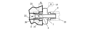
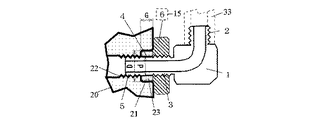
【0003】図1(ストレート型の管継手構造の従来例説明断面図である)と図2(L字型の管継手構造の従来例説明断面図である)とを用いて従来例の管継手構造を説明をする。従来、車両や産業機器等の高圧流体(油・空気・水等)を扱う高圧機器や部品(被接続部20)と、鋼管やチューブなどの管部材33とを相互接続する為に管継手1は用いられていた。
【0004】この種の管継手構造は、図1、図2に示するように管継手1の内部に形成された流路と同軸に雄ねじ5が形成されており、また、被接続部20には開口する流路と同軸に雌ねじ22が形成されている。そして、管継手1の雄ねじ5と雌ねじ22とを螺着することにより、管継手1が被接続部20に取り付けられるようになつていた。
【0005】
【発明が解決しようとする課題】
これら管継手構造は高圧流体を扱うために、ねじによる接続だけでは密封性が得られないので、オーリング23を介在させていた。そのために被接続部20にはオーリング23を挿入して密封作用させる為に、雌ねじ22の口元に溝21が設けられていた。この溝21はグランド溝やV溝やあり溝や隅角溝などが知られている。
【0006】図1および図2の従来例では、被接続部20に締め付けホイル8により閉じられてオーリング23を保持する溝21を形成している。この溝21は高圧の密封効果を得る為に、精度良く製作され、精度管理される事が必要であった。例えば雌ね22の外径がφ10位の場合は、溝21の溝内径Dの許容公差は+0.05、−0mmが求められていた。更にその溝21の各隅はR面加工してオーリング23の損傷を防ぐ必用が有った。また溝幅Gも精度良く作る必用が有った。
【0007】一方、管継手1においても図1の例では締め付け用の部材としての締め付けホイル8と雄ねじ5との間に、溝幅G以上の長さの平らな平滑軸4を設ける必用がつた。この平滑軸4の平滑軸外径dは、通常のねじ逃げ加工と異なりその外径が精度良く製作され管理される必用があった。例えば前記の被接続部20に対応する場合は+0、−0.06mmの許容公差で製作する事が求められていた。
【0008】図2のL字型の例では出力方向を任意な方向とする為に、締め付け用としての部材として格別な締め付けナット6が設けられた構造となっている。その為にナット用雄ねじ3と雄ねじ5の間に前記の平滑軸4が作られる必要が有った。この平滑軸4は、図1の第1の従来例と同様に高い工作精度で作る事と、その精度管理が求められていた。
【0009】この様に従来の管継手構造は被接続部20と管継手1との2つ部品にそれぞれ、高精度加工と精度管理が求められていた。従ってこれらが有るために作業工程の短縮が出来ず、そのために高圧流体を扱う製品自体が高価となる欠点が有った。
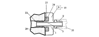
【0010】一方前記の欠点を解決するものとして、出願番号 特願2001−78491の配管継手構造が知られている。その構造について図3(オーリング付き締め付け部材による従来例説明断面図である)を用いて簡単に説明する。締め付けホイル8あるいは締め付けナット6(図示は略す)の被接続部20側の面にオーリング23を収納する為の収納凹部24を設け、内部にオーリング23を設けて、管継手1を被接続部20に締め付けるように構成している。
【0011】この様に構成するので、締め付け部材15でオーリング23を被接続部20の面に押圧する事ができるので、密封性が容易に得られる構造であり、更に図1と図2の様な高精度な加工も無く廉価な配管継手構造が得られる事が特徴で有る事が知られていた。しかし、この従来例のものは管継手1の締め付け課程で発生するオーリング23の劣化の問題を残していた。以下詳細に説明する。
【0012】回転する締め付け部材15で保持されたオーリング23は、螺着時に被接続部20の面に単純に押圧されるだけで無く、その面で回転摺動する構造になっていた。その為に高圧を密封するためにオーリング23を強く押圧すると、その押圧に応じて面との摩擦力や、面とのくさび効果が増加して、オーリング23は内部歪みを発生させ部分的に弾性限界を超え弾性体としての作用を失ったり、また剪断応力により部分的に切断される危険を内在していた。
【0013】従って高圧流体を扱う管継手構造としては、初期値においては目的は達したとしても、長期にわたる安定した密封度確保の課題を残していた。
【0014】本発明の目的は、かかる欠点を無くし、管継手1と被接続部20の製作を容易にし、長期にわたり安定した密封効果を有する高圧流体用の管継手構造を提供するものである。
【0015】
【課題を解決する手段】
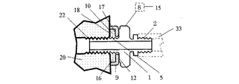
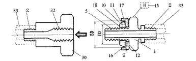
本発明の管継手構造について図4(第1実施例の管継手構造説明断面図である)と図5(実施例の弾性部材と王冠部材との詳細説明断面図である)と図6(第2実施例の管継手構造説明断面図である)と図7(第3実施例の管継手構造説明断面図である)を用いて簡単に説明する。
【0016】請求項1に示すように、被接続部20の平坦面に対して垂直に形成された雌ねじ22に管継手1を螺着する高圧流体用の管継手構造において、被接続部20の平坦面に対して垂直に形成された雌ねじ22に管継手1の雄ねじ5を螺着する高圧流体用の管継手構造において、高い剛性のある金属で王冠状の王冠部材9を設け、かつ締め付け部材15で回動しないように、上面は平滑に下面は平坦に王冠部材9を形設して設け、更に下面の径を上面の径より小さな径とした筒状の肉厚な弾性体による弾性部材10を構成し、更に王冠部材9の内部に弾性部材10を設け、弾性部材10を内装した王冠部材9を被接続部20と締め付け部材15との間に構成して管継手構造を構成する。
【0017】次に前記の王冠部材9は請求項2のように構成する。即ち王冠部材9は、上面の王冠上面12に雄ねじ5より大きな径で貫通した王冠孔14を設けるとともに、王冠上面12と下面の王冠底面16とは平行に形設し、且つ王冠上面12は、外周および王冠孔14の面取り処理を含み平滑に形設し、王冠底面16は、面取り無しで端面全体で被接続部20に密着するように平坦に形設して王冠部材9を構成するとともに、一方、締め付け部材15の王冠部材9に接する面は面取り処理を含み平滑に形設して構成して管継手構造を構成する。
【0018】また前記の弾性部材10は請求項3のように構成する。即ち弾性部材10は、中央に雄ねじ5の外径とほぼ同じ径の貫通した弾性孔13を設けた筒状で且つ王冠部材9の内部高さより30%以上大きい高さの肉厚で形設し、更に王冠部材9に接触する面の弾性上面17と被接続部20に接触する面の弾性底面18とは平行に形設するととともに、弾性底面18の弾性底面径TDは弾性上面17の弾性上面径SDより小さくなるように弾性部材10を形設して構成して管継手構造を構成する。
【0019】この様に構成するので、王冠部材9は締め付け部材15で回動されないで軸方向にのみ押圧され、被接続部20の面に密着する。よつて被接続部20の面と雌ねじ22と雄ねじ5と締め付け部材15とを、王冠部材9の内部の弾性部材10で密封する事が出来る。
【0020】更に弾性部材10は高い押圧下での回動はしないので、内部歪みや剪断応力を受ける事は無い。よつて高圧流体でも長期にわたり安定した密封効果を得る事が出来る。
【0021】更に弾性底面径TDを弾性上面径SDより小さくしたので、王冠底面16と被接続部20の間に弾性部材10を部分的に挟み込んでしまう事が無く、密封効果を下げる事がない。
【0022】また通常の精度で製作できる王冠部材9や弾性部材10を用いる事で、高精度加工や精度管理を必要とする被接続部20の溝21と管継手1の平滑軸4が不要となり廉価に管継手構造を提供出来る。
【0023】複雑な高圧機器などを含む被接続部20は大型の複雑な形状のものが多い。この大型の被接続部20を高精度加工の出来る工場に持ち込む必要が無い事と、弾性部材10や王冠部材9は小型で有る事より、工程節減や扱いやすさからも管継手構造全体を廉価に提供出来る。
【0024】弾性部材10を内蔵した王冠部材9を、締め付け部材15と被接続部20の間に単純に配設するだけなので、作業性も良く、容易に管継手構造が構成できる。
【0025】
【発明の実施の形態】
最も最良と考える本発明の実施の形態(発明をどのように実施するか)を、添付図(図4〜図7)に基づいてその構成と作用と効果を説明する。
【0026】
(第1の実施例)
始めに図5を用いて構成要素となる王冠部材9と弾性部材10との詳細説明をする。壁状の王冠上面12で筒の一端が閉ざされた王冠状の形状の王冠部材9を高い剛性のある金属で設ける。
【0027】その王冠上面12の中央には雄ねじ5の回動に無関係とするように雄ねじ5よりも大きな内径の貫通した王冠孔14を設けるとともに、王冠上面12に平行となるように平面に王冠部材12の被接続部20に面する端面の王冠底面16を構成する。
【0028】次に管継手1の雄ねじ5を貫通可能な内径の弾性孔13を有する肉厚な筒状の弾性体で弾性部材10を設け、その弾性部材10を王冠部材9の内部に設ける。
【0029】更にその弾性部材10の肉厚は、締め付け以前の状態の弾性部材10の弾性肉厚SHを、王冠部材9の内部の高さの王冠内部高さWKより30%以上大きい肉厚で設ける。
【0030】また更に王冠部材9に接触する面の弾性上面17と被接続部20に接触する面の弾性底面18とを平行に形成するとともに、弾性底面18の径は弾性上面17の外径より小さくなるように弾性部材10の外周を斜面状にした弾性斜面11を設けて弾性部材10を構成する。
【0031】次に弾性部材10について補足する。弾性部材10の弾性体は密封性と耐久性を得るように、ニトリルゴムやシリコンゴムやフッ素ゴム等を用いて構成する。更に弾性孔13の径は雄ねじ5の外径とほぼ同じに選定する。(その径を雄ねじ5の谷径を超えて小さくする事は装着時に弾性部材10に損傷を与える原因となるので好ましくない。またその径があまり大きいと雄ねじ5より落下するので作業性より雄ねじ5の外径にほぼ同じとする方がよい。)
【0032】次に弾性底面18の径である弾性底面径SDは、弾性上面17の外径の弾性上面径SDより小さくなるように弾性部材10の外周を斜面状にした弾性斜面11を設けるが、その弾性斜面11の形状は、使用する弾性体が30%以上押圧されて王冠部材9の中で広がり王冠底面16よりはみ出ない様な形状に実験的に求めればよい。
【0033】例えば図5は、押圧されていない時の状態でのφ10の雄ねじ5に適した王冠部材9と弾性部材10の例を示している。王冠部材9の内部の高さの王冠内部高さWKは2.5mm、弾性部材10の高さの弾性肉厚SHは3.8mm、弾性上面径SDはφ15、弾性底面径TDはφ13となるように弾性斜面11を選定して構成している。
【0034】原則的には王冠部材9で弾性底面18は回転しないように構成されている。よって弾性底面径TDのエッジの面取りは任意でよい。(R面やC面や面取り無しなど)。更に王冠底面16よりはみ出ない様にする為の弾性斜面11の形状は、図5の折れ線状の面や、後述する図6の階段状の面や、図7の直線状の面や曲面状の面など任意で弾性底面径TDが、弾性上面径SDより小さくなるように構成する。
【0035】次に王冠部材9に付いて補足する。回転しながら押圧する締め付け部材15に対向する王冠上面12の表面は、十分平滑になるように仕上げる。更に王冠上面12の形状は滑りやすいように大きなR面(例えば2Rの面)やC面で面取りをする。またメッキなどで表面を滑りやすくする事は好ましい。
【0036】王冠底面16は王冠上面12と平行になるように仕上げるが、焼き入れ鋼で王冠部材9を製作したときは研削処理して平行平面度を出す。この精度は±0.1程度の通常の仕上げで良い。この王冠底面16は回転しにくいように、その端面はR面やC面の面取りはしないで被接続部20の面との密着度を上げるようにする。(面取りをしない方が被接続部20に接した時に、くさび効果で回転しにくくなる傾向がある。)
【0037】また王冠上面12には王冠孔14を設けるが、雄ねじ5の外径より十分大きな内径(例えば雄ねじ5がφ10の時はφ10.3など)として設ける。この孔の締め付け部材15側の表面も回動しないようにR面やC面の面取り処理をする。
【0038】次に管継手1について図4に示す第1の実施例(ストレート型)のものを説明する。管継手1の本体には内部に形成された流路と同軸に管33を接続する管接続部2と締め付け部材15としての締め付けホイル8と被接続部20に接続する雄ねじ5を設ける。
【0039】この管継手1の本体には従来有った精度を要する平滑軸4は不要であるので、雄ねじ5は締め付け部材15の近傍より任意に構成する事が出来る。
【0040】次に前述の王冠部材9と弾性部材10を、被接続部20と締め付け部材15との間に王冠上面12が締め付け部材15側になるように配設して第1の実施例の管継手構造は構成する。
【0041】締め付け部材15について補足する。王冠上面12は回動しないように前記の様に配慮をしたが、締め付け部材15も王冠上面12に対向する面は、王冠部材9を回動しないように平滑に仕上げる。例えば回転方向に滑りやすいようにR面やC面で面取りをする。
【0042】このようにに構成するので、(王冠部材9の王冠上面12と王冠底面16とは平行に作られるので、)締め付け部材15を締め付けた状態では被接続部20との隙間も無く王冠部材9の内部が密室状態になると同時に、中にある弾性部材10は、軸方向に圧縮されて王冠部材9の内部で3次元的に広がり被接続部20の面および雌ねじ22や管継手1の雄ねじ5や王冠部材9の内面に密着する。
【0043】また更に弾性底面18の径は弾性上面17の外径より小さいので押圧されて内部で広がっても、王冠底面16と被接続部20の間に部分的に挟み込むような事が無いので、隙間が出来て密封度が下がる事が無い。
【0044】また締め付け部材15と王冠上面12と王冠底面16は、締め付けにより王冠部材9を回動しないように配慮した構造となっているので、内部の弾性部材10に回動による内部歪みや剪断応力を与える事が無く弾性体としての性能が保持されるので、長期にわたって安定した密封度をを確保できる。
【0045】このように第1の実施例の管継手構造は確実に密封度が得られるので高圧の流体の管継手構造としては簡単な構造で優れた特性が得られる。例えば第1の実施例の水圧試験では20Mpa以上の性能を得ている。
【0046】更に管継手1の本体側や被接続部20には高精度加工を要求する溝21や平滑軸4を設ける必要が無いので、そのための加工工数と精度管理など不要となり、この節減効果により廉価に管継手構造を提供出来る。特に被接続部20は複雑な高圧流体の機構を内在した大型の機器が多いので、被接続部20の工数節減効果は更に大きくなる。また締め付け部材15にオーリング23を内蔵した従来のもののような不安定さも無い。
【0047】王冠部材9は通常の精度で作れるの事と、小型の部品である事と、平滑の配慮だけで作れることより、全体の管継手構造を廉価に提供出来る。
【0048】
(第2の実施例)
本発明の第2の実施例としてL字型の管継手構造を図6を用いて説明する。管継手1の本体内部の流路がL字型に曲げられた構造のものであり、そのために管33の引き回し方向が任意な方向に出来るように締め付け部材15は締め付けナット6として構成する。従ってナット用雄ねじ3と雄ねじ5が管継手1の本体には必要になるが、両者を1つのねじに共通化可能であり、図6では雄ねじ5で共通化した構成している。よつて連続して雄ねじ5が作れるので工程の節減が出来る。
【0049】また弾性斜面11の形状は階段状に設けて被接続部20の雌ねじ22のC面の中まで入り込み易くして、雌ねじ22の密封度を上げるようにしている。
【0050】また第2の実施例の締め付けナット6は、王冠上面12に対向する押圧面を平滑に配慮して製作する。それ以外の全体の構成と作用と効果は図4の第1の実施例と同じであるので重複を避けるために詳細説明は省略する。
【0051】
(第3の実施例)
本発明の応用展開例として第3の実施例で一方の管33と他方の管33を接続する中継用の管継手構造を図7を用いて説明する。
【0052】この管継手構造は一方の管33を図4で説明した管継手1と同様な管接続部2に接続して設け、また前記の管継手1と接続する為の中継部材30の管接続部2に他方の管33は接続して構成する。
【0053】更に内部の流路の開口部に管継手1の雄ねじ5に適合する中継雌ねじ32を設けて中継部材30を構成する。(この中継雌ねじ32は被接続部20の雌ねじ22と同じもので良い。)この中継部材30の開口面(王冠底面16に対向する面)は被接続部20と同様に中継雌ねじ32の軸に対して垂直な平面として構成する。
【0054】このように構成したので、弾性部材10を内蔵した王冠部材9を配設した管継手1と、中継部材30とを螺着する事により、一方の管33と他方の管33を簡単に高圧流路の中で密封した状況で簡単に確実に中継する事が出来る。
【0055】本発明の管継手構造は中継用としても、中継部材30に特別な精度を要求する溝21など不要になるので、廉価に中継が可能となり、しかも長期にわたり安定した密封度を確保出来る中継装置を提供出来る。
【0056】本発明の管継手構造の構成は主旨を逸脱しない範囲で応用展開や変更しても良い。例えば図7の第3の実施例のような中継部材30の管継手構造に応用展開する事や、第3の実施例の図7に示すように弾性斜面11を、弾性上面径SDより弾性底面径TDまでを連続的に径が変化する斜面としても良い。(図5では弾性上面径SDで外周が途中まで作られ、その途中から徐々に径が小さくなるように弾性斜面11が折れ線状の面で設けられている。)
【0057】
【発明の効果】
本発明は、以上説明したようなものであるから、以下に記載されるような効果を奏する。
【0058】1)管継手1本体に高精度の加工を求める平滑軸4を形成する必要が無いので、工数節減と精度管理が不要となり管継手構造全体を廉価に提供できる
【0059】2)被接続部20に高精度の加工を求める溝21を形成する必要が無いので、工数節減と精度管理が不要となり管継手構造全体を廉価に提供できる。
【0060】3)溝21を形成する必用が無いので、複雑な高圧流体機構を有する大型な被接続部20を、精密加工する次の行程へ移動したりする事が無いので、工数節減により管継手構造全体を廉価に提供できる。
【0061】4)小型の王冠部材9と弾性部材10を通常精度で製作するだけなので、管継手構造全体を廉価に提供できる。
【0062】5)王冠上面12と、その面に対向する締め付け部材15の面を平滑にし、且つ王冠底面16の端面は平坦にし密着度を上げたので、王冠部材9は容易に回動しないので、回動による内部歪みや剪断応力を弾性部材10が受けて弾性特性を変質するような事が無く、長期にわたり高圧を密封する事が出来る。
【0063】6)王冠上面12と王冠底面16とを平行にしたので、締め付け部材15による螺着が振動でゆるむ事が無い。
【0064】7)押圧されても王冠底面16と被接続部20の間に弾性部材10を挟み込む事がないように予め弾性底面18を弾性上面17よりも小さな径としたので、部分的にはみ出して密封効果を下げる事が無い。
【0065】8)締め付け部材15と被接続部20の間に配設出来るように予め管継手1の本体に弾性部材10を内蔵した王冠部材9を配設し、その配設した管継手1を締め付けるだけで管継手構造が容易に構成できるので、作業性も良い。
【0066】9)本発明の管継手構造は、高圧(例えば20Mpa以上)流体用に適した性能を有している。
【0067】このように本発明は従来の多くの問題を解決した優れた管継手構造を提供出来る。
【図面の簡単な説明】
【図1】ストレート型の管継手構造の従来例説明断面図である。
【図2】L字型の管継手構造の従来例説明断面図である。
【図3】オーリング付き締め付け部材 による従来例説明断面図である。
【図4】第1実施例の管継手構造説明断面図である。
【図5】実施例の弾性部材と王冠部材との詳細説明断面図である。
【図6】第2実施例の管継手構造説明断面図である。
【図7】第3実施例の管継手構造説明断面図である。
【符号の説明】
1 管継手
2 管接続部
3 ナット用雄ねじ
4 平滑軸
5 雄ねじ
6 締付けナット
8 締め付けホイル
9 王冠部材
10 弾性部材
11 弾性斜面
12 王冠上面
13 弾性孔
14 王冠孔
15 締め付け部材
16 王冠底面
17 弾性上面
18 弾性底面
20 被接続部
21 溝
22 雌ねじ
23 オーリング
24 収納凹部
30 中継部材
32 中継雌ねじ
33 管
d 平滑軸外径
D 溝内径
G 溝幅
SD 弾性上面径
SH 弾性肉厚
TD 弾性底面径
WK 王冠内部高さ[0001]
TECHNICAL FIELD OF THE INVENTION
The present invention relates to a straight joint, an L-shaped joint, a T-shaped joint, a cruciform joint, etc., which are screwed with a screw hole, and in particular, facilitates production of a pipe joint and a connected portion, and achieves a long-term stable sealing effect. The present invention relates to a pipe joint structure for a high-pressure fluid having the same.
[0002]
[Prior art]
Regarding the reference numerals of the drawings used in the description of the present invention, those having the same operation and the like are represented by the same reference numerals in order to avoid repetition of the description. In the description of the elastic member 10 and the crown member 9 described below, unless otherwise noted, the right side will be described as the top side of the component, and the left side will be described as the bottom side of the component. Furthermore, a generic name of a fastening wheel 8 or a fastening nut 6 described later is abbreviated as a fastening member 15. In addition, a high-pressure device or a component to which the pipe joint 1 is fixed will be abbreviated as a connected portion 20 hereinafter.
FIG. 1 (a cross-sectional view illustrating a conventional example of a straight type pipe joint structure) and FIG. 2 (a cross-sectional view illustrating a conventional example of an L-shaped pipe joint structure) are used. The structure will be described. Conventionally, a pipe joint 1 for interconnecting a high-pressure device or a part (connected portion 20) that handles a high-pressure fluid (oil, air, water, etc.) such as a vehicle or an industrial device and a pipe member 33 such as a steel pipe or a tube. Was used.
In this type of pipe joint structure, as shown in FIGS. 1 and 2, a male screw 5 is formed coaxially with a flow path formed inside the pipe joint 1, and Is formed with a female screw 22 coaxially with the opening channel. Then, by screwing the male screw 5 and the female screw 22 of the pipe joint 1, the pipe joint 1 is attached to the connected portion 20.
[0005]
[Problems to be solved by the invention]
Since these pipe joint structures handle high-pressure fluid, sealing cannot be obtained only by connection with screws, so the O-ring 23 is interposed. For this purpose, a groove 21 is provided at the mouth of the female screw 22 in order to insert the O-ring 23 into the connected portion 20 to perform a sealing action. The groove 21 is known as a ground groove, a V groove, a dovetail groove, a corner groove, or the like.
In the conventional example shown in FIGS. 1 and 2, a groove 21 which is closed by a fastening wheel 8 and holds an O-ring 23 is formed in a connected portion 20. In order to obtain a high-pressure sealing effect, the groove 21 needs to be manufactured with high precision and controlled in precision. For example, when the outer diameter of the female socket 22 is about φ10, the allowable tolerance of the groove inner diameter D of the groove 21 is required to be +0.05 and −0 mm. Further, each corner of the groove 21 had to be rounded to prevent the O-ring 23 from being damaged. Also, the groove width G had to be made with high precision.
On the other hand, in the case of the pipe joint 1 in the example of FIG. 1, it is necessary to provide the flat smooth shaft 4 having a length equal to or more than the groove width G between the tightening wheel 8 as a tightening member and the male screw 5. . The smooth shaft outer diameter d of the smooth shaft 4 has to be manufactured and controlled with high precision, unlike ordinary screw relief processing. For example, in the case of corresponding to the above-mentioned connected part 20, it has been required to manufacture with a tolerance of +0, -0.06 mm.
The L-shaped example of FIG. 2 has a structure in which a special tightening nut 6 is provided as a member for tightening in order to set the output direction to an arbitrary direction. Therefore, it was necessary to form the smooth shaft 4 between the male screw 3 for the nut and the male screw 5. As with the first conventional example shown in FIG. 1, the smooth shaft 4 is required to be manufactured with high machining accuracy and its accuracy management is required.
As described above, in the conventional pipe joint structure, high precision machining and precision control are required for the two parts, the connected part 20 and the pipe joint 1. Therefore, the work steps cannot be shortened because of these, and there is a disadvantage in that the product handling high-pressure fluid itself becomes expensive.
On the other hand, as a solution to the above-mentioned drawback, a pipe joint structure disclosed in Japanese Patent Application No. 2001-78491 is known. The structure will be briefly described with reference to FIG. 3 (a sectional view illustrating a conventional example using a fastening member with an O-ring). A housing recess 24 for housing the O-ring 23 is provided on the surface of the tightening wheel 8 or the tightening nut 6 (not shown) on the connected portion 20 side, and the O-ring 23 is provided therein to connect the pipe joint 1. It is configured to be fastened to the part 20.
With such a configuration, the O-ring 23 can be pressed against the surface of the connected portion 20 by the fastening member 15, so that the sealing property can be easily obtained, and the structure shown in FIGS. It has been known that an inexpensive pipe joint structure can be obtained without such high-precision processing. However, this conventional example has a problem of deterioration of the O-ring 23 generated during the tightening process of the pipe joint 1. The details will be described below.
The O-ring 23 held by the rotating fastening member 15 is not only simply pressed against the surface of the connected portion 20 at the time of screwing, but also has a structure in which the O-ring 23 slides on the surface. Therefore, when the O-ring 23 is strongly pressed to seal the high pressure, the frictional force with the surface and the wedge effect with the surface increase in accordance with the pressing, and the O-ring 23 generates internal distortion and partially In addition, there is an inherent danger of exceeding the elastic limit, losing the function as an elastic body, and being partially cut by shear stress.
Therefore, a pipe joint structure for handling a high-pressure fluid has a problem that a long-term stable degree of sealing must be ensured even if the object is achieved at an initial value.
An object of the present invention is to provide a pipe joint structure for high-pressure fluid which eliminates the above drawbacks, facilitates the manufacture of the pipe joint 1 and the connected portion 20, and has a stable sealing effect over a long period of time.
[0015]
[Means to solve the problem]
The pipe joint structure of the present invention is shown in FIG. 4 (a cross-sectional view illustrating the pipe joint structure of the first embodiment), FIG. 5 (a detailed cross-sectional view of the elastic member and the crown member of the embodiment), and FIG. It is simply explained using FIG. 7 (which is a cross-sectional view for explaining the pipe joint structure of the third embodiment) and FIG. 7 (which is a cross-sectional view for explaining the pipe joint structure of the third embodiment).
According to a first aspect of the present invention, in a pipe joint structure for a high-pressure fluid in which the pipe joint 1 is screwed into a female screw 22 formed perpendicular to a flat surface of the connected section 20, In a pipe joint structure for high-pressure fluid in which a male screw 5 of a pipe joint 1 is screwed to a female screw 22 formed perpendicular to a flat surface, a crown member 9 having a crown shape made of a highly rigid metal is provided, and a fastening member is provided. The crown member 9 is formed so that the upper surface is smooth and the lower surface is flat so as not to rotate at 15, and furthermore, a cylindrical elastic member made of a thick elastic body having a lower surface smaller in diameter than the upper surface. 10, the elastic member 10 is further provided inside the crown member 9, and the crown member 9 having the elastic member 10 therein is formed between the connected portion 20 and the fastening member 15 to form a pipe joint structure.
Next, the crown member 9 is constructed as in claim 2. That is, the crown member 9 is provided with a crown hole 14 penetrating with a diameter larger than the male screw 5 in the crown top surface 12 on the top surface, the crown top surface 12 and the crown bottom surface 16 on the bottom surface are formed in parallel, and the crown top surface 12 is The crown member 9 is formed in a smooth shape including chamfering of the outer periphery and the crown hole 14, and the crown bottom surface 16 is formed flat so as to be in close contact with the connected portion 20 on the entire end surface without chamfering, On the other hand, the surface of the fastening member 15 which is in contact with the crown member 9 is formed to have a smooth shape including a chamfering process, thereby forming a pipe joint structure.
Further, the elastic member 10 is configured as in claim 3. That is, the elastic member 10 is formed in a cylindrical shape having a through-hole elastic hole 13 having a diameter substantially the same as the outer diameter of the male screw 5 at the center, and formed with a thickness greater than the inner height of the crown member 9 by 30% or more. Further, the elastic upper surface 17 of the surface contacting the crown member 9 and the elastic bottom surface 18 of the surface contacting the connected portion 20 are formed in parallel, and the elastic bottom surface diameter TD of the elastic bottom surface 18 is the elastic upper surface of the elastic upper surface 17. The pipe joint structure is formed by forming and configuring the elastic member 10 so as to be smaller than the diameter SD.
With such a configuration, the crown member 9 is pressed only in the axial direction without being rotated by the fastening member 15, and is brought into close contact with the surface of the connected portion 20. Thus, the surface of the connected portion 20, the female screw 22, the male screw 5, and the fastening member 15 can be sealed by the elastic member 10 inside the crown member 9.
Further, since the elastic member 10 does not rotate under a high pressure, it does not receive internal strain or shear stress. Therefore, a stable sealing effect can be obtained for a long time even with a high-pressure fluid.
Further, since the elastic bottom diameter TD is smaller than the elastic top diameter SD, the elastic member 10 is not partially sandwiched between the crown bottom surface 16 and the connected portion 20, and the sealing effect is not reduced. .
Further, the use of the crown member 9 and the elastic member 10 which can be manufactured with normal precision eliminates the need for the groove 21 of the connected portion 20 and the smooth shaft 4 of the pipe joint 1 which require high precision processing and precision control. A pipe joint structure can be provided at low cost.
The connected portion 20 including a complicated high-voltage device or the like often has a large and complicated shape. There is no need to bring this large connected part 20 to a factory where high-precision processing is possible, and the elastic member 10 and the crown member 9 are small in size. Can be provided.
Since the crown member 9 incorporating the elastic member 10 is simply disposed between the fastening member 15 and the connected portion 20, workability is good and a pipe joint structure can be easily formed.
[0025]
BEST MODE FOR CARRYING OUT THE INVENTION
The configuration, operation, and effects of the embodiment of the present invention (how to implement the invention) which is considered to be the best will be described based on the attached drawings (FIGS. 4 to 7).
[0026]
(First embodiment)
First, the crown member 9 and the elastic member 10, which are constituent elements, will be described in detail with reference to FIG. A crown-shaped crown member 9 in which one end of a cylinder is closed at a wall-shaped crown upper surface 12 is provided with a highly rigid metal.
At the center of the crown upper surface 12, a penetrating crown hole 14 having an inner diameter larger than that of the male screw 5 is provided so as to be unrelated to the rotation of the male screw 5, and the crown is formed in a plane parallel to the crown upper surface 12. The crown bottom surface 16 of the end face of the member 12 facing the connected portion 20 is formed.
Next, the elastic member 10 is provided as a thick cylindrical elastic body having an elastic hole 13 with an inner diameter capable of penetrating the male screw 5 of the pipe joint 1, and the elastic member 10 is provided inside the crown member 9.
Further, the thickness of the elastic member 10 is set such that the elastic thickness SH of the elastic member 10 before tightening is 30% or more larger than the crown inner height WK of the inner height of the crown member 9. Provide.
Further, the elastic upper surface 17 of the surface contacting the crown member 9 and the elastic bottom surface 18 of the surface contacting the connected portion 20 are formed in parallel, and the diameter of the elastic bottom surface 18 is larger than the outer diameter of the elastic upper surface 17. The elastic member 10 is formed by providing an elastic slope 11 in which the outer periphery of the elastic member 10 is inclined so as to be small.
Next, the elastic member 10 will be supplemented. The elastic body of the elastic member 10 is made of nitrile rubber, silicon rubber, fluorine rubber, or the like so as to obtain sealing performance and durability. Further, the diameter of the elastic hole 13 is selected to be substantially the same as the outer diameter of the male screw 5. (Reducing the diameter beyond the root diameter of the male screw 5 is not preferable because it causes damage to the elastic member 10 at the time of mounting. If the diameter is too large, it falls down from the male screw 5, so that the male screw 5 cannot be removed due to workability. It is better to be almost the same as the outer diameter of
Next, an elastic slope 11 is provided in which the outer periphery of the elastic member 10 is inclined so that the elastic bottom diameter SD, which is the diameter of the elastic bottom surface 18, is smaller than the elastic upper surface diameter SD of the outer diameter of the elastic upper surface 17. The shape of the elastic slope 11 may be experimentally determined so that the elastic body to be used is pressed by 30% or more and spreads in the crown member 9 so as not to protrude from the crown bottom surface 16.
For example, FIG. 5 shows an example of the crown member 9 and the elastic member 10 suitable for the φ10 male screw 5 when not pressed. The crown inner height WK of the height inside the crown member 9 is 2.5 mm, the elastic thickness SH of the height of the elastic member 10 is 3.8 mm, the elastic upper surface diameter SD is φ15, and the elastic bottom diameter TD is φ13. The elastic slope 11 is selected and configured as described above.
In principle, the elastic bottom surface 18 of the crown member 9 is configured not to rotate. Therefore, the chamfering of the edge having the elastic bottom diameter TD may be arbitrary. (No R surface, C surface or chamfer). Further, the shape of the elastic slope 11 for preventing the protrusion from protruding from the crown bottom surface 16 is as follows: a polygonal surface in FIG. 5, a step-like surface in FIG. 6 described later, a linear surface or a curved surface in FIG. The elastic bottom surface diameter TD is arbitrarily smaller than the elastic upper surface diameter SD.
Next, the crown member 9 will be supplemented. The surface of the crown upper surface 12 facing the fastening member 15 pressed while rotating is finished so as to be sufficiently smooth. Further, the shape of the crown upper surface 12 is chamfered on a large R surface (for example, a 2R surface) or a C surface so as to be slippery. It is also preferable to make the surface slippery by plating or the like.
The crown bottom surface 16 is finished so as to be parallel to the crown top surface 12, but when the crown member 9 is made of hardened steel, it is ground to obtain a parallel flatness. This accuracy may be a normal finish of about ± 0.1. To prevent the crown bottom 16 from rotating easily, the end face thereof is not chamfered on the R-plane or the C-plane and the degree of close contact with the surface of the connected portion 20 is increased. (The one without chamfering tends to be less likely to rotate due to the wedge effect when in contact with the connected part 20.)
A crown hole 14 is provided on the crown upper surface 12, and is provided with an inner diameter sufficiently larger than the outer diameter of the male screw 5 (for example, when the male screw 5 is φ10, φ10.3). The chamfering process of the R surface and the C surface is performed so that the surface of the hole on the side of the fastening member 15 does not rotate.
Next, the pipe joint 1 of the first embodiment (straight type) shown in FIG. 4 will be described. The main body of the pipe joint 1 is provided with a pipe connecting part 2 for connecting the pipe 33 coaxially with a flow path formed therein, a fastening foil 8 as a fastening member 15, and a male screw 5 for connecting to the connected part 20.
Since the main body of the pipe joint 1 does not require the smooth shaft 4 which requires the precision conventionally required, the male screw 5 can be arbitrarily formed from the vicinity of the tightening member 15.
Next, the crown member 9 and the elastic member 10 described above are arranged between the connected portion 20 and the fastening member 15 so that the crown upper surface 12 is on the fastening member 15 side. The pipe joint structure is composed.
The supplementary description of the fastening member 15 will be given. Although the crown upper surface 12 has been considered so as not to rotate as described above, the surface of the tightening member 15 facing the crown upper surface 12 is also finished smoothly so that the crown member 9 does not rotate. For example, chamfering is performed on the R surface or the C surface so as to be slippery in the rotation direction.
With such a configuration, the crown upper surface 12 and the crown bottom surface 16 of the crown member 9 are formed in parallel with each other. At the same time as the inside of the member 9 is closed, the elastic member 10 inside is compressed in the axial direction and spreads three-dimensionally inside the crown member 9, and the surface of the connected portion 20 and the internal thread 22 and the pipe joint 1 are removed. The inner screw 5 and the inner surface of the crown member 9 are in close contact with each other.
Further, since the diameter of the elastic bottom surface 18 is smaller than the outer diameter of the elastic upper surface 17, even if the elastic bottom surface 18 is pressed and spreads inside, there is no possibility that the elastic bottom surface 18 is partially sandwiched between the crown bottom surface 16 and the connected portion 20. There is no gap and the degree of sealing is not reduced.
The tightening member 15, the crown upper surface 12, and the crown bottom surface 16 are structured so as not to rotate the crown member 9 by tightening. Since the performance as an elastic body is maintained without applying a stress, a stable sealing degree can be secured for a long period of time.
As described above, the pipe joint structure of the first embodiment can surely obtain the degree of sealing, so that excellent characteristics can be obtained with a simple structure as a pipe joint structure for high-pressure fluid. For example, in the water pressure test of the first embodiment, a performance of 20 Mpa or more is obtained.
Further, since it is not necessary to provide the groove 21 and the smooth shaft 4 which require high-precision machining on the main body side and the connected portion 20 of the pipe joint 1, the man-hour and accuracy control for the machining are not required, and this saving effect is obtained. Thus, a pipe joint structure can be provided at a low cost. In particular, since the connected portion 20 is often a large-sized device having a complicated high-pressure fluid mechanism therein, the effect of reducing the man-hour of the connected portion 20 is further increased. Further, there is no instability unlike the conventional one in which the O-ring 23 is built in the fastening member 15.
Since the crown member 9 can be made with normal accuracy, a small component, and can be made only by considering smoothness, the entire pipe joint structure can be provided at low cost.
[0048]
(Second embodiment)
An L-shaped pipe joint structure will be described as a second embodiment of the present invention with reference to FIG. The passage inside the main body of the pipe joint 1 has a structure bent into an L-shape, so that the clamping member 15 is configured as a clamping nut 6 so that the pipe 33 can be drawn in any direction. Therefore, although the male screw 3 for the nut and the male screw 5 are required for the main body of the pipe joint 1, both can be shared by one screw, and the male screw 5 is used in common in FIG. Accordingly, since the male screw 5 can be continuously formed, the number of steps can be reduced.
Further, the shape of the elastic slope 11 is provided in a step-like manner so that it can easily enter the C-plane of the female screw 22 of the connected portion 20, and the degree of sealing of the female screw 22 is increased.
The tightening nut 6 according to the second embodiment is manufactured with smoothness of the pressing surface facing the crown upper surface 12. The rest of the configuration, operation, and effects are the same as those of the first embodiment shown in FIG. 4, so that detailed description is omitted to avoid duplication.
[0051]
(Third embodiment)
A relay pipe joint structure for connecting one pipe 33 and the other pipe 33 in a third embodiment will be described with reference to FIG. 7 as an application example of the present invention.
In this pipe joint structure, one pipe 33 is provided by connecting it to a pipe connection 2 similar to the pipe joint 1 described with reference to FIG. 4, and the pipe of the relay member 30 for connecting to the pipe joint 1 is provided. The other pipe 33 is connected to the connection part 2 and configured.
Further, a relay female screw 32 which is adapted to the male screw 5 of the pipe joint 1 is provided in the opening of the internal flow path to constitute the relay member 30. (The relay female screw 32 may be the same as the female screw 22 of the connected portion 20.) The opening surface of the relay member 30 (the surface facing the crown bottom surface 16) is connected to the axis of the relay female screw 32 in the same manner as the connected portion 20. It is configured as a plane perpendicular to the plane.
With this configuration, the pipe joint 1 provided with the crown member 9 containing the elastic member 10 and the relay member 30 are screwed together, so that the one pipe 33 and the other pipe 33 can be simplified. It can be easily and reliably relayed in a sealed state in a high-pressure flow path.
The pipe joint structure of the present invention does not require the groove 21 which requires special precision in the relay member 30 even for relay, so that the relay can be performed at a low cost and a stable sealing degree can be secured for a long period of time. A relay device can be provided.
The configuration of the pipe joint structure of the present invention may be applied or changed without departing from the gist of the invention. For example, the present invention can be applied to the pipe joint structure of the relay member 30 as in the third embodiment shown in FIG. 7, or the elastic slope 11 can be formed as shown in FIG. The slope up to the diameter TD may be a slope whose diameter continuously changes. (In FIG. 5, the outer periphery is made partway with the elastic upper surface diameter SD, and the elastic slope 11 is provided as a polygonal surface so that the diameter gradually decreases from that part of the way.)
[0057]
【The invention's effect】
Since the present invention is as described above, the following effects can be obtained.
1) Since it is not necessary to form the smooth shaft 4 for high-precision machining in the body of the pipe joint 1, it is possible to save man-hours and eliminate the need for precision control, and to provide the entire pipe joint structure at a low cost. Since it is not necessary to form the groove 21 requiring high-precision processing in the connecting portion 20, the number of steps can be reduced and accuracy control can be eliminated, and the entire pipe joint structure can be provided at a low cost.
3) Since there is no need to form the groove 21, the large connected portion 20 having a complicated high-pressure fluid mechanism does not need to be moved to the next step for precision machining. The entire joint structure can be provided at low cost.
4) Since the small crown member 9 and the elastic member 10 are simply manufactured with normal accuracy, the entire pipe joint structure can be provided at a low cost.
5) The crown upper surface 12 and the surface of the tightening member 15 opposed to the crown upper surface 12 are smoothed, and the end surface of the crown bottom surface 16 is flattened to increase the degree of adhesion, so that the crown member 9 does not rotate easily. In addition, the elastic member 10 does not receive the internal strain or the shear stress due to the rotation, thereby deteriorating the elastic characteristic, and can seal the high pressure for a long time.
6) Since the crown upper surface 12 and the crown bottom surface 16 are parallel, the screwing by the fastening member 15 does not loosen due to vibration.
7) Since the elastic bottom surface 18 has a smaller diameter than the elastic upper surface 17 in advance so that the elastic member 10 is not sandwiched between the crown bottom surface 16 and the connected portion 20 even when pressed, it partially protrudes. It does not lower the sealing effect.
8) The crown member 9 having the elastic member 10 built therein is previously disposed on the main body of the pipe joint 1 so that the pipe joint 1 can be disposed between the fastening member 15 and the connected portion 20. The workability is good because the pipe joint structure can be easily configured simply by tightening.
9) The pipe joint structure of the present invention has a performance suitable for a high-pressure fluid (for example, 20 Mpa or more).
As described above, the present invention can provide an excellent pipe joint structure which has solved many conventional problems.
[Brief description of the drawings]
FIG. 1 is a cross-sectional view illustrating a conventional example of a straight type pipe joint structure.
FIG. 2 is an explanatory sectional view of a conventional example of an L-shaped pipe joint structure.
FIG. 3 is an explanatory sectional view of a conventional example using a fastening member with an O-ring.
FIG. 4 is an explanatory sectional view of the pipe joint structure of the first embodiment.
FIG. 5 is a detailed explanatory sectional view of an elastic member and a crown member of the embodiment.
FIG. 6 is an explanatory sectional view of a pipe joint structure according to a second embodiment.
FIG. 7 is an explanatory sectional view of a pipe joint structure according to a third embodiment.
[Explanation of symbols]
DESCRIPTION OF SYMBOLS 1 Pipe joint 2 Pipe connection part 3 Male screw for nut 4 Smooth shaft 5 Male screw 6 Tightening nut 8 Tightening foil 9 Crown member 10 Elastic member 11 Elastic slope 12 Crown top surface 13 Elastic hole 14 Crown hole 15 Clamping member 16 Crown bottom surface 17 Elastic top surface 18 Elastic bottom surface 20 Connected portion 21 Groove 22 Female screw 23 O-ring 24 Storage concave portion 30 Relay member 32 Relay female screw 33 Tube d Smooth shaft outer diameter D Groove inner diameter G Groove width SD Elastic upper surface diameter SH Elastic wall thickness TD Elastic bottom diameter WK Inside crown height