JP2004190866A - Ventilator - Google Patents
Ventilator Download PDFInfo
- Publication number
- JP2004190866A JP2004190866A JP2002355411A JP2002355411A JP2004190866A JP 2004190866 A JP2004190866 A JP 2004190866A JP 2002355411 A JP2002355411 A JP 2002355411A JP 2002355411 A JP2002355411 A JP 2002355411A JP 2004190866 A JP2004190866 A JP 2004190866A
- Authority
- JP
- Japan
- Prior art keywords
- ventilation
- air
- air volume
- bathroom
- room
- Prior art date
- Legal status (The legal status is an assumption and is not a legal conclusion. Google has not performed a legal analysis and makes no representation as to the accuracy of the status listed.)
- Granted
Links
- 238000009423 ventilation Methods 0.000 claims abstract description 222
- 238000007599 discharging Methods 0.000 claims abstract description 7
- 230000004044 response Effects 0.000 abstract description 3
- 238000010438 heat treatment Methods 0.000 description 8
- 238000001035 drying Methods 0.000 description 7
- CURLTUGMZLYLDI-UHFFFAOYSA-N Carbon dioxide Chemical compound O=C=O CURLTUGMZLYLDI-UHFFFAOYSA-N 0.000 description 4
- WSFSSNUMVMOOMR-UHFFFAOYSA-N Formaldehyde Chemical compound O=C WSFSSNUMVMOOMR-UHFFFAOYSA-N 0.000 description 3
- 230000000694 effects Effects 0.000 description 3
- 238000003825 pressing Methods 0.000 description 3
- OKTJSMMVPCPJKN-UHFFFAOYSA-N Carbon Chemical compound [C] OKTJSMMVPCPJKN-UHFFFAOYSA-N 0.000 description 2
- 238000013459 approach Methods 0.000 description 2
- 238000003287 bathing Methods 0.000 description 2
- 229910052799 carbon Inorganic materials 0.000 description 2
- 239000001569 carbon dioxide Substances 0.000 description 2
- 229910002092 carbon dioxide Inorganic materials 0.000 description 2
- 238000010586 diagram Methods 0.000 description 2
- 239000012855 volatile organic compound Substances 0.000 description 2
- 241000238876 Acari Species 0.000 description 1
- 206010019233 Headaches Diseases 0.000 description 1
- 206010020751 Hypersensitivity Diseases 0.000 description 1
- 208000026935 allergic disease Diseases 0.000 description 1
- 230000007815 allergy Effects 0.000 description 1
- QVGXLLKOCUKJST-UHFFFAOYSA-N atomic oxygen Chemical compound [O] QVGXLLKOCUKJST-UHFFFAOYSA-N 0.000 description 1
- 239000004566 building material Substances 0.000 description 1
- 238000004364 calculation method Methods 0.000 description 1
- 238000009833 condensation Methods 0.000 description 1
- 230000005494 condensation Effects 0.000 description 1
- 238000010276 construction Methods 0.000 description 1
- 238000001816 cooling Methods 0.000 description 1
- 230000007423 decrease Effects 0.000 description 1
- 230000003247 decreasing effect Effects 0.000 description 1
- 230000002950 deficient Effects 0.000 description 1
- 238000009408 flooring Methods 0.000 description 1
- 231100000869 headache Toxicity 0.000 description 1
- 238000005286 illumination Methods 0.000 description 1
- 230000001771 impaired effect Effects 0.000 description 1
- WSFSSNUMVMOOMR-NJFSPNSNSA-N methanone Chemical compound O=[14CH2] WSFSSNUMVMOOMR-NJFSPNSNSA-N 0.000 description 1
- 235000019645 odor Nutrition 0.000 description 1
- 229910052760 oxygen Inorganic materials 0.000 description 1
- 239000001301 oxygen Substances 0.000 description 1
- 230000002093 peripheral effect Effects 0.000 description 1
Images

Landscapes
- Ventilation (AREA)
Abstract
Description
【0001】
【発明の属する技術分野】
本発明は、一戸建てやマンションの住宅等の時間当たりにおける常時換気風量を一定に保つ換気装置に関する。
【0002】
【従来の技術】
最近の住宅は、高気密化や高断熱化が進んでいる一方、新築住宅・新規家具・カーテンでは、カーペット、フローリング、クロス等の建材からホルムアルデヒドや揮発有機化合物を発散することが知られている。
【0003】
このため、キッチンのレンジフードファンや、バスルーム、洗面室、トイレ等から屋外に強制的に排気するダクトファン等を頻繁に起動させて適切な換気を行い、二酸化炭素、ホルムアルデヒド、VOC等の濃度及び湿度を低く維持し、アレルギーの発生を防ぐことが好ましい。
【0004】
特に、閉め切った室内で石油ファンヒータ等を長時間換気なしで使用したために、酸欠状態となったり、二酸化炭素濃度が高まって頭痛等を引き起こすことや、湿度が高くなってカビやダニが発生し、アレルギーの因子となっている等が問題とされており、マンション等の高気密性住宅においては、頻繁な換気が望まれている。
【0005】
そこで、住宅内の換気を常時行う24時間換気を行うことが求められている。この24時間換気とは、常時換気を低風量で行うものであり、マンションの住宅では、各室内の必要換気風量を満たすように、例えば、各室内の容積の0.5回/毎時程度の換気が必要とされている。この24時間換気の風量は予め必要風量が得られるように住宅の施工時に設定される。
【0006】
そこで、複数の室内を同時に換気する場合、各室内の局所換気スイッチがオンされると、換気スイッチのオンされた吸込口の開口面積を増大させる一方、他の部屋の吸込口の開口面積を狭小化し、更に換気装置のファン回転数を増大させることによって局所換気風量を確保しようとするものがある。
【0007】
尚、多室換気に関する先行技術としては、特許文献1に示す「複室換気装置」が知られている。この「複室換気装置」は「浴室、トイレ、洗面所を換気」し、「浴室の湿気がトイレ、洗面所に浸入したり、トイレの臭気が浴室、洗面所に漏れないようにすること」を目的とするもので、「送風機の吸気側に浴室側吸気口、トイレ側吸気口、洗面所吸気口を形成し、この各吸気口をダンパーで開閉自在とし、1つのダンパーを開くことで1つの室を換気できるし、各室相互が連通しないようにする」ものである。
【0008】
【特許文献1】
特開平10−73297号公報(0004〜0080、図1,図2)
【0009】
【発明が解決しようとする課題】
しかし、従来の局所換気方式では、局所換気の対象となる部屋の換気が開始されても、他の部屋の吸込口の開口面積は「0」とはならず、それぞれの部屋の換気を同時に行うため、局所換気を行おうとする以外の部屋に換気風量を奪われてしまい、局所換気対象の部屋の換気風量が十分に得られない可能性があった。また、局所換気風量を確保しようとすると、ファンの回転数を上げなくてはならないため、騒音が増大する可能性があった。
【0010】
更に、従来、トイレや浴室を換気した場合、住宅全体の総換気風量が変化するため、気密性の高いマンションや戸建て住宅では、総排気量が多すぎると、夏場では冷房等の省エネルギー効果が損なわれ、冬場では自然吸気口からの通気風量が強くなり、暖房効果が低下する問題がある。
【0011】
また、風圧の強いときには、住宅の外側に臨む排気口から配管を介して住宅内に空気が逆流するため、換気風量が低下したり、空気の逆流による配管周りに結露が発生するという問題もある。
【0012】
本願は、このような問題に着目してなされたものであり、24時間換気を行う場合に、外気の風圧の変動に拘わらず、住宅の総換気風量を一定に保ちつつ、各部屋に応じた適当な局所換気を行うことができる換気装置を提供することを目的とする。
【0013】
【課題を解決するための手段】
上記課題を解決するために、本願の第1の換気装置は、複数の室内から空気を吸い込む複数の吸込口と、該複数の吸込口から住宅内の空気を吸い込んで住宅の外側に排気することにより換気を行う空気排出手段と、前記複数の吸込口から吸い込んで排出する対象エリアが必要とする総換気風量を満たしつつ、個々の室内に応じて換気風量を制御する制御手段とを設けたことを特徴とする。
【0014】
本願の第2の換気装置は、複数の室内からそれぞれ空気を吸引する複数の吸込口を備え、該複数の吸込口から住宅内の空気を吸い込んで住宅の外部に排出する空気排出手段を備えた換気装置であって、前記空気排出手段を制御する制御手段に、対象エリアの常時換気を行う常時換気モードを設けると共に、該常時換気モードの実行中は、対象エリアにおける常時換気風量を一定に保ちつつ、個々の室内における換気風量を所定風量となるように制御する風量制御機能を設けたことを特徴とする。
【0015】
本願の第3の換気装置は、第1,第2の何れかの換気装置において、前記複数の吸込口に風量調整手段を設けたことを特徴とする。
【0016】
本願の第4の換気装置は、請求項1乃至請求項3何れか記載の換気装置において、前記複数の吸込口のうち選択された吸込口からの換気風量を基準として、選択されていない吸込口の換気風量を選択時より少なくし、対象エリアが必要とする換気風量になるように、風量調整手段を調整することを特徴とする。
【0017】
【発明の実施の形態】
以下、本願の実施の形態にかかる換気装置について図面に基づいて説明する。
【0018】
図2〜図4は、浴室、脱衣室等に設置される換気装置本体1の主要な構成を模式的に示したものである。換気装置本体1の外側を覆う本体ケース2は、浴室3の天井に取り付けられる。本体ケース2には、図2,図3にも示すように、上下二段ユニットが設けられ、浴室側の下部ユニット6には、浴室3の空気を吸引する円筒型の遠心型の循環ファン7を配設する吸引開口部8と、吸い込んだ空気を浴室3に循環する循環風路9と、浴室3の空気を上部ユニット13に案内する第1の吸込口14とが形成されている。第1の吸込口14にはダンパーD1が設けられている。
【0019】
下部ユニット6の循環ファン7は、ファンケース10内部に格納されており、ファンケース10に浴室3内の空気を吸引するための吸引開口部8が形成されている。循環風路9には、PTCヒータ(Positive Temperature Coefficientヒータ)11が配備されている。循環用排気開口部の近傍にサーミスタからなる図示しない温度センサが設置されている。尚、PTCヒータ11の他にカーボンヒータ12を設けても良い。カーボンヒータ12は入浴暖房モードを設けた際に輻射熱により入浴者を暖めることが出来る。
【0020】
循環ファン7を回転させるためのファンモータM2は、ファンケース10の上部に取り付けられ、ファンモータM2の出力軸には循環ファン7が固定されている。
【0021】
上部ユニット13は、浴室3の他に洗面所・居室等の他の部屋からの空気を換気するための換気機構を構成する。上部ユニット13のケース13A下部には吸引開口部15が形成されている。この吸引開口部15は下部ユニット6との隙間Sを経由して浴室3に通じる第1の吸込口14に通じており、浴室3の空気を上部ユニット13内に吸引した後に上部ユニット13、本体ケース2の排気口16から排気(換気)可能とされている。17Aは排気口16に臨むように本体ケース2に設けられたダクトジョイントであり、ダクトジョイント17Aに排気ダクト18Aが接続されている。
【0022】
上部ユニット13のファンケース13A内部には換気ファン23が設けられており、換気ファン23はファンモータM1により回転される。換気ファン23が回転すると、第1吸込口14及び吸引開口部15から空気を吸い込んで上部ユニット13の内壁に沿って移動させ、排気口16からダクトジョイント17A、ダクト18Aから建物外に排気(換気)する。
【0023】
本体ケース2の側壁部には、図3に示すように、浴室以外の洗面所や他の室内の換気を行うための第2吸込口19,第3吸込口20,第4吸込口21が開口されており、これらの吸込口19、20にはダンパーD2,D3が設けられていると共に、それぞれダクトジョイント17Bが設けられており、ダクトジョイント17Bに吸気ダクト22が接続されている。第4吸込口21は閉鎖されている。
【0024】
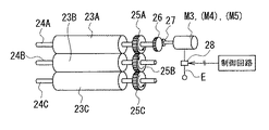
第1吸込口14と第2吸込口19,第3吸込口20のダンパーD1〜D3は風量調整手段として設けられている。これらのダンパーD1〜D3は、図5に示すように、3枚の遮蔽板23A、23B、23Cとこれらの遮蔽板23A、23B、23Cの中央部に設けられた回転軸24A、24B、24Cと、回転軸24A、24B、24Cの端部に取り付けられたギア25A、25B、25Cとを備えている。
【0025】
回転軸24A、24B、24Cの両端部は、吸込口19〜21の相対する縁部に回転可能に保持されており、ギア25A、25B、25Cは吸込口19〜21の外側に位置するように設置される。3本の回転軸のうちの一つの回転軸24Aには、駆動用のギア26が固定されており、ギア26はダンパーモーターM3(以下、ダンパーD1,D2も同様にダンパーモーターM4,M5に駆動される。)の出力軸に固定されたギア27に噛み合っており、ダンパーモーターM3によって駆動される。なお、ダンパーD1,D2も同様な機構を介してダンパーモーターM4,M5により駆動される。
【0026】
ダンパーモーターM3はインターフェースとしてのモーター駆動回路28に接続されている。ダンパーモーターM4,M5も同様にモーター駆動回路29,30に接続されている。モーター駆動回路28〜30は、ダンパーモーターM3、M4,M5の正転と反転とを切り換える回路を備えており、制御ユニット31の制御によってダンパーモーターM3,M4,M5の正逆回転を行うように供給電力を制御する。制御ユニット31(図3参照)は上部ユニット13の上部に設けられている。尚、ダンパーモーターは回転可能であれば、正逆回転式でなくても良い。
【0027】
制御ユニット31の制御基板には、マイクロコンピュータ32と、電源回路とその他の周辺回路を備えている。制御ユニット31は、ファンモータM1,M2、モーター駆動回路28,29,30、PTCヒータ11等を制御する。
【0028】
電源回路は、家庭内の商用電源の電力をPTCヒータ11、ファンモータM1,M2、ダンパーモーターM3、M4,M5に供給すると共に、商用電源を低圧の直流に変換してマイクロコンピュータ32に供給する。
【0029】
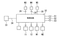
マイクロコンピュータ32には、図6に示すように、PTCヒータ11、温度センサ、ファンモータM1,M2、ダンパーモーターM3、M4,M5、浴室照明スイッチS1、洗面所換気スイッチS2、トイレ換気スイッチS3が接続されている。
【0030】
浴室照明スイッチS1は、浴室の入り口壁面等に設けられた照明用の電源スイッチの接地線に抵抗・整流器からなる直列回路を並列接続したもので、導通時に電圧を低下させてマイクロコンピュータ32に照明が点灯されたことを検知する。洗面所換気スイッチS2、トイレ換気スイッチS2は、浴室・洗面所・トイレに設置される換気スイッチにより構成される。
【0031】
また、マイクロコンピュータ32には、制御線34を介してリモートコントローラ33が接続されている。リモートコントローラ33は、乾燥ボタンB1、涼風ボタンB2、暖房ボタンB3、換気ボタンB4、24時間換気ボタンB5、タイマー切換ボタンB6、タイマー合わせアップボタンB7、タイマー合わせダウンボタンB8、リセットスイッチB9、LCD、LED1,LED2を有する。
【0032】
マイクロコンピュータ32は、リモートコントローラ33からの操作命令に基づいて動作制御プログラムを起動する。
【0033】
動作制御プログラムは、上記の操作ボタンB1〜B9の操作に応じて動作し、乾燥モードと、涼風モードと、換気モードと、タイマーモードと、24時間換気モードとを有する。動作制御プログラムにおける24時間換気モードでは、浴室の照明スイッチS1、洗面所換気スイッチS2、トイレ換気スイッチS3のオンオフ状態をも考慮して風量を調整する。
【0034】
「乾燥」ボタンB1が押されると、換気装置本体1が乾燥モードとなり、循環ファンモーターM2が高速で回転すると共に、換気ファンモーターM1が中速で回転し、更に、PTCヒータ11が発熱して、衣類等の乾燥が可能となる。
【0035】
「涼風」ボタンB2が押されると、換気装置本体1が涼風モードとなり、循環ファンモーターM2が高速で回転し、換気ファンモーターM1が中速で回転する。
【0036】
「暖房」ボタンB3が押されると、換気装置本体1が暖房モードになり、循環ファンヒータM2が高速で回転すると共に、PTCヒータ11が発熱する。換気ファンモーターM1は回転しない。
【0037】
「換気」ボタンB4には、換気強B4aと換気弱B4bとが設けられている。換気ボタンB4の換気強B4aが押されると、換気装置本体1が換気強モードとなり、換気ファンモーターM1が高速回転する。換気ボタンB4の換気弱B4bが押されると、換気装置本体1が換気弱モードとなり、換気ファンモーターM1が低速回転する。また、浴室照明スイッチS1がオンとされた状態で、換気ボタンB4が押されているときは、入力換気モードとなり、換気ファンモーターM1は最低速度で回転する。
【0038】
これらの操作ボタンB1〜B8の操作をすると、制御線34を介して指定された命令信号が換気装置本体1に送信され、換気装置本体1が指定された「暖房」「涼風」「乾燥」「換気」の動作を行う。
【0039】
乾燥ボタンB1、涼風ボタンB2、暖房ボタンB3、換気ボタンB4は、それぞれボタンを押すと、バックライト照明が点灯して、指定した動作が行われていることを表示する。
【0040】
タイマーモードでは、リモートコントローラ33から送られてきた動作要求に基づいて、動作制御プログラムの各動作モードを選択し、その動作モードを命令された時間に開始し、終了する。
【0041】
LED1は、タイマー合わせアップボタンB7やダウンボタンB8を押したときに、タイマー切換ボタンB6を押すことによって、選択動作を開始する、入り時刻(動作開始時刻)を表示する。LED2は、タイマー合わせアップボタンB7やダウンボタンB8を押したときに、タイマー切換ボタンB6を押すことによって、選択動作を停止する切り残時間(動作残時間)を表示する。
【0042】
24時間換気ボタンB5は、24時間換気を行うことを命令するボタンであり、24時間換気ボタンB5を3秒以内の時間だけ押すと、換気用ファン23が回転し、24時間換気が開始される。
【0043】
この24時間換気とは、常時換気を低風量で行うものであり、マンションでは、対象エリアである各室内の単位時間当たりの必要換気風量(換気回数、例えば、各室内の容積の0.5回/時間程度の換気が必要となっている。)を満たすように、マンション・戸建ての住宅等における延べ床面積に高さを乗じた容積に応じた時間当たりの換気風量が設定される。対象エリアとはマンションや戸建て住宅によって異なるが、住宅内の同一フロア内にあるものでも良く、また、複数エリアにまたがって対象エリアとしても良い。
【0044】
24時間換気ボタンB5を3秒以上押すと、24時間換気が停止する。24時間換気が停止されると、LCD32に24時間換気が停止されていることが点滅表示され、ユーザーに示される。
【0045】
動作制御プログラムにおける24時間換気モードは、換気装置本体1の風量調整プログラムを有する。
【0046】
この風量調整プログラムは、乾燥・暖房・涼風・換気等の操作ボタンB、浴室照明スイッチS1、洗面所スイッチS2、トイレスイッチS3のオンオフ状態の組合せにより、換気ファンモーターM1の換気風量を選択し、ダンパーD1〜D3の開度を選択する。
【0047】
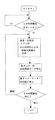
即ち、図1に示すように、24時間換気ボタンB5が押されると(ステップ1)、風量調整プログラムが開始され、換気ボタンB5、浴室照明スイッチS1、洗面所スイッチS2、トイレスイッチS3のオンオフ状態が判別され(ステップ2)、記憶した対応テーブルから、換気ボタンB5の操作内容と、浴室照明スイッチS1、洗面所スイッチS2、トイレスイッチS3のオンオフ状態とに対応した総換気風量が決定される。
【0048】
ステップ2において、換気ボタンB5の操作内容と、浴室照明スイッチS1、洗面所スイッチS2、トイレスイッチS3のオンオフ状態によって、総換気風量が決められた後には、記憶した対応テーブルからダンパーD1〜D3の対応開度データが呼び出される(ステップ3)。
【0049】
ステップ3でダンパーD1〜D3の対応開度データが呼び出されたら、対応開度データに対応するように、ダンパーモーターM3,M4,M5を回転させ、ダンパーD1〜D3を所定の対応開度にする(ステップ4)。尚、ダンパーD1〜D3の開度は選択されたもののうち、最大となるものを基準(例えば全開)として決められている。
【0050】
例えば、24時間換気ボタンB5が押された24時間換気モード下において、換気ボタンB4、洗面所スイッチS2、トイレスイッチS3が全てオフであれば、浴室、洗面所、トイレの総換気風量は例えば60立方メートル(以下立方メートルは省略する)としてあり、ダンパーD1〜D3の開度調整では、各吸込口から吸い込んで排出する風量は40である。
【0051】
24時間換気モードに加えて、浴室の局所換気が選択されているときには、総換気風量は70となり、浴室の換気風量は60で洗面所とトイレの換気風量はそれぞれ10となる。
【0052】
また、24時間換気モードに加えて、浴室と洗面所の2つの局所換気が選択されているときには、浴室と洗面所での必要な換気風量を合算し、更にトイレの最低風量を合算した総換気風量は80となり、浴室が50、洗面所が30、トイレが0となる。24時間換気モードに加えて、浴室とトイレの局所換気が選択されているときは、前記算出法により、総換気風量は170となり、浴室が60、洗面所10,トイレ40という風量になる。この実施の形態では最低風量を10としたが、この値はこれに限らず、0でも良い。
【0053】
要は、24時間換気モード下にあって、浴室、洗面所、トイレの何れかの換気が求められているときは、該当する室内の換気は最大設定風量となり、該当しない室内の風量は少量となっている。
【0054】
また、24時間換気モード下であり、且つ、浴室に入浴中の場合には、浴室、洗面所、トイレの総換気風量は80を保ったままとして、浴室の換気はいずれも最低風量10とし、洗面所・トイレを30とする。浴室に入浴中で洗面所の換気が選択されれば、洗面所を最大風量40とし、トイレを30とする。トイレの換気が選択されれば、トイレを40とし、洗面所を30として速く排出したいと思われるトイレを優先する。
【0055】
また、24時間換気モード下であり、且つ、乾燥モード又は涼風モードが選択されている場合には、浴室、洗面所、トイレの総換気風量は最低の60を基準とする。この状態で、浴室の乾燥ボタンB1・涼風ボタンB2が選択されているときは、浴室の換気風量は中速で40が選択される。浴室の換気風量40に対して洗面所・トイレのいずれもが選択されていなければ、洗面所・トイレは10とされる。浴室の換気風量40に対して洗面所が選択されれば洗面所が30とされ、トイレが0とされる。また、浴室の換気風量40に対して、トイレが選択されればトイレが30となり、洗面所が0となる。
【0056】
更に、24時間換気モード下において、暖房ボタンB3が押されたときには、浴室の換気風量は0とされ、洗面所・トイレはスイッチのオンオフに拘わらず、30とされる。
【0057】
浴室・洗面所・トイレのいずれも換気する状態にあるときは、浴室を60とし、洗面所・トイレをそれぞれ40として総換気風量130と最大とすることも可能であり、浴室・洗面所・トイレのいずれも40として総換気風量を120とすることも可能である。
【0058】
以上説明したように、この実施の形態にかかる換気装置は、複数の室内からそれぞれ空気を吸い込む第1の吸込口14,第2の吸込口19,第3の吸込口20を備えており、この複数の吸込口14,19,20から住宅内の空気を吸い込んで住宅の外側に排気することにより換気を行う換気ファン23と、上記吸込口14,19,20から吸い込んで排出する対象エリアが必要とする総換気風量を一定に保ちつつ、個々の室内に応じて換気風量を制御するマイクロコンピュータ32(制御手段)と、吸込口14,19,20にダンパーD1〜D3及びダンパーモーターM3、M4,M5(風量調整手段)とを設けたものである。
【0059】
そして、マイクロコンピュータ32は、住宅全体の常時換気を行う24時間換気モード(常時換気モード)を設けると共に、24時間換気モードの実行中は、住宅全体における総換気風量若しくは複数の室内の総換気風量の何れかを一定に保ちつつ、個々の室内における換気風量を所定風量となるように制御するものである。
【0060】
対象エリアの必要とする常時換気風量(換気回数)は、前述のように、各室内の容積(0.5回/h)によってきまっている。また、浴室、洗面所、トイレそれぞれが選択された場合の局所換気風量が決まっている。選択されたエリアの換気風量を一定に制御し、選択されていないエリアについては、住宅全体の対象エリアの常時換気風量を満たし、その必要な常時換気風量に近づけるように設定した値に制御している。各風量の数値については記載したものに限定されるものではなく、対象エリアにより種々多様である。
【0061】
特に、局所換気を行う浴室や洗面所、トイレ等の特定の吸込口の換気風量を基準として、その他の室内の吸込口の換気風量を当該室内に合わせて室内の換気風量を抑制する風量とするように、ダンパーモーターM3、M4,M5を調整するので、24時間換気モードにおける総換気風量を一定に保ちつつ、局所換気を十分に行うことができる。
【0062】
また、風量センサ等を設け、各室内の風量を所定回数になるように、制御プログラムで演算して制御しても良い。
【0063】
尚、本発明の換気装置は浴室換気装置について説明したがこれに限定されるものではなく、室内用換気装置にも適用可能なものである。
【0064】
【発明の効果】
本願の第1の換気装置によれば、住宅全体等の対象エリアに必要な総換気風量を一定に保ちつつ、個々の室内に応じた換気風量を確保可能となる。
【0065】
本願の第2の換気装置によれば、常時換気(低送風量による24時間の換気)を行いつつ、複数の室内に応じた適切な換気を行うことができる。
【0066】
本願の第3の換気装置によれば、複数の吸込口に設けた風量調整手段を制御手段によって制御することにより、住宅全体等の対象エリア若しくは複数の室内の総換気風量を維持しつつ、各室内の換気風量を増減して各室内に応じた換気風量を得ることができる。
【0067】
本願の第4の換気装置によれば、選択された室内(例えば、浴室等)の換気風量を一定にし、その他の室内の換気風量を各々の室内に応じて適切な換気風量に調整することが出来、住宅全体の総換気風量が一定値に近くなる。
【図面の簡単な説明】
【図1】本発明の実施の形態にかかる換気装置の風量制御の流れを示す流れ図。
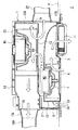
【図2】図1の換気装置の断面図。
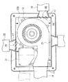
【図3】図1の換気装置の上部平断面図。
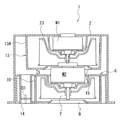
【図4】図1の換気装置の縦断面図。
【図5】風量調整手段としてのダンパーの機構を示す概略図。
【図6】制御手段としてのマイクロコンピュータのブロック図。
【図7】リモートコントローラの平面図。
【符号の説明】
1 換気装置本体
14 第1の吸込口
19 第2の吸込口
20 第3の吸込口
23 換気ファン
D1〜D3 ダンパー
M1 換気モーター
M2 循環モーター
M3 ダンパーモーター
M4 ダンパーモーター
M5 ダンパーモーター
32 マイクロコンピュータ
33 リモートコントローラ[0001]
TECHNICAL FIELD OF THE INVENTION
TECHNICAL FIELD The present invention relates to a ventilator for constantly maintaining a constant ventilation air volume per hour, such as a detached house or a condominium house.
[0002]
[Prior art]
Recent houses are becoming more airtight and more heat-insulating, while new houses, new furniture and curtains are known to emit formaldehyde and volatile organic compounds from building materials such as carpets, flooring and cloths. .
[0003]
For this reason, a range hood fan in a kitchen, a duct fan forcibly exhausting air from a bathroom, a washroom, a toilet, and the like to the outside are frequently started to perform appropriate ventilation, and a concentration of carbon dioxide, formaldehyde, VOC, etc. It is preferable to keep the humidity low and prevent allergy from occurring.
[0004]
In particular, since the oil fan heaters etc. were used in a closed room without ventilation for a long time, they became oxygen deficient, the concentration of carbon dioxide increased, causing headaches, etc., and the humidity increased, causing mold and ticks However, frequent ventilation is desired in highly airtight houses such as condominiums.
[0005]
Therefore, it is required to perform 24-hour ventilation, which constantly performs ventilation in a house. The 24-hour ventilation is to constantly perform ventilation at a low air flow. In a condominium house, for example, ventilation of about 0.5 times / hour of the volume of each room to satisfy the required ventilation air volume in each room. Is needed. The air volume of this 24-hour ventilation is set in advance at the time of construction of a house so that a required air volume is obtained.
[0006]
Therefore, when simultaneously ventilating a plurality of rooms, when the local ventilation switch in each room is turned on, the opening area of the suction port where the ventilation switch is turned on is increased, while the opening area of the suction port of another room is reduced. In some cases, a local ventilation air volume is secured by increasing the number of fan rotations of the ventilation device.
[0007]
As a prior art relating to multi-chamber ventilation, a “multi-chamber ventilator” disclosed in Patent Document 1 is known. This "multi-chamber ventilation system""ventilates bathrooms, toilets and toilets" and "prevents bathroom moisture from entering toilets and toilets, and does not leak toilet odors into bathrooms and toilets." A bathroom-side intake, a toilet-side intake, and a lavatory intake are formed on the intake side of the blower, and each of the intakes can be freely opened and closed by a damper, and one damper is opened. One room can be ventilated and each room should not communicate with each other. "
[0008]
[Patent Document 1]
JP-A-10-73297 (0004 to 0080, FIGS. 1 and 2)
[0009]
[Problems to be solved by the invention]
However, in the conventional local ventilation system, even if the ventilation of a room to be subjected to local ventilation is started, the opening area of the suction port of another room does not become “0”, and the ventilation of each room is performed simultaneously. Therefore, there is a possibility that the room other than the one trying to perform the local ventilation loses the ventilation air volume, and the ventilation air volume of the room targeted for the local ventilation cannot be sufficiently obtained. Also, in order to secure the local ventilation air volume, the number of rotations of the fan must be increased, so that the noise may increase.
[0010]
Furthermore, conventionally, when the toilets and bathrooms are ventilated, the total ventilation air volume of the entire house changes, so that in a highly airtight apartment or a detached house, if the total exhaust amount is too large, the energy saving effect such as cooling in summer is impaired. However, in winter, there is a problem in that the amount of ventilation air from the natural air intake increases and the heating effect decreases.
[0011]
In addition, when the wind pressure is strong, the air flows back into the house from the exhaust port facing the outside of the house via the pipe, so that there is a problem that the ventilation air volume is reduced and dew condensation occurs around the pipe due to the backflow of the air. .
[0012]
The present application has been made in view of such a problem, and when performing ventilation for 24 hours, irrespective of the fluctuation of the wind pressure of the outside air, the total ventilation air volume of the house is kept constant, and the room is adapted to each room. An object of the present invention is to provide a ventilation device that can perform appropriate local ventilation.
[0013]
[Means for Solving the Problems]
In order to solve the above-described problems, a first ventilator of the present application includes a plurality of air inlets for sucking air from a plurality of rooms, and sucking air in a house from the plurality of air inlets and exhausting the air to the outside of the house. Air exhaust means for providing ventilation, and control means for controlling the amount of ventilation air according to each room while satisfying the total ventilation air volume required by the target area to be sucked and discharged from the plurality of suction ports. It is characterized by.
[0014]
The second ventilator of the present application includes a plurality of suction ports for sucking air from a plurality of rooms, respectively, and includes an air discharge unit that sucks air in the house from the plurality of suction ports and discharges the air outside the house. A ventilator, wherein a control means for controlling the air discharging means is provided with a constant ventilation mode for constantly ventilating the target area, and while the constant ventilation mode is being executed, the constant ventilation air volume in the target area is kept constant. In addition, an air volume control function for controlling the ventilation air volume in each room to be a predetermined air volume is provided.
[0015]
A third ventilation device according to the present invention is characterized in that, in any one of the first and second ventilation devices, an air volume adjusting means is provided at the plurality of suction ports.
[0016]
The fourth ventilator of the present application is the ventilator according to any one of claims 1 to 3, wherein the suction port that is not selected based on a ventilation air volume from a suction port selected from the plurality of suction ports. Is characterized in that the airflow adjusting means is adjusted so that the ventilation airflow of the target area is reduced to the required ventilation airflow.
[0017]
BEST MODE FOR CARRYING OUT THE INVENTION
Hereinafter, a ventilation device according to an embodiment of the present application will be described with reference to the drawings.
[0018]
FIGS. 2 to 4 schematically show the main configuration of the ventilation device main body 1 installed in a bathroom, a dressing room, or the like. The
[0019]
The
[0020]
A fan motor M2 for rotating the
[0021]
The
[0022]
A
[0023]
As shown in FIG. 3, a
[0024]
The
[0025]
Both ends of the
[0026]
The damper motor M3 is connected to a
[0027]
The control board of the
[0028]
The power supply circuit supplies the power of the domestic commercial power supply to the
[0029]
As shown in FIG. 6, the
[0030]
The bathroom lighting switch S1 is a switch in which a series circuit composed of a resistor and a rectifier is connected in parallel to a ground wire of a power switch for lighting provided on the entrance wall of the bathroom or the like. It detects that is lit. The toilet ventilation switch S2 and the toilet ventilation switch S2 are configured by ventilation switches installed in bathrooms, toilets, and toilets.
[0031]
Further, a
[0032]
The
[0033]
The operation control program operates in response to the operation of the operation buttons B1 to B9, and has a drying mode, a cool air mode, a ventilation mode, a timer mode, and a 24-hour ventilation mode. In the 24-hour ventilation mode in the operation control program, the air volume is adjusted in consideration of the on / off state of the bathroom lighting switch S1, the bathroom ventilation switch S2, and the toilet ventilation switch S3.
[0034]
When the "dry" button B1 is pressed, the ventilation device body 1 enters a drying mode, the circulation fan motor M2 rotates at high speed, the ventilation fan motor M1 rotates at medium speed, and the
[0035]
When the "cool air" button B2 is pressed, the ventilation device body 1 enters the cool air mode, the circulation fan motor M2 rotates at high speed, and the ventilation fan motor M1 rotates at medium speed.
[0036]
When the "heating" button B3 is pressed, the ventilation device main body 1 enters the heating mode, the circulation fan heater M2 rotates at a high speed, and the
[0037]
The “ventilation” button B4 is provided with strong ventilation B4a and weak ventilation B4b. When the strong ventilation B4a of the ventilation button B4 is pressed, the ventilation device body 1 enters the strong ventilation mode, and the ventilation fan motor M1 rotates at a high speed. When the weak ventilation B4b of the ventilation button B4 is pressed, the ventilation device body 1 enters the weak ventilation mode, and the ventilation fan motor M1 rotates at a low speed. If the ventilation button B4 is pressed with the bathroom lighting switch S1 turned on, the input ventilation mode is set, and the ventilation fan motor M1 rotates at the minimum speed.
[0038]
When these operation buttons B1 to B8 are operated, a command signal designated via the
[0039]
When each of the drying button B1, the cool air button B2, the heating button B3, and the ventilation button B4 is pressed, the backlight illumination is turned on to indicate that the specified operation is being performed.
[0040]
In the timer mode, each operation mode of the operation control program is selected based on the operation request sent from the
[0041]
The LED 1 displays an entry time (operation start time) at which the selection operation is started by pressing the timer switching button B6 when the timer adjustment up button B7 or the down button B8 is pressed. The
[0042]
The 24-hour ventilation button B5 is a button for instructing to perform 24-hour ventilation. When the 24-hour ventilation button B5 is pressed for a time within 3 seconds, the
[0043]
The 24-hour ventilation is to constantly perform ventilation at a low air volume. In an apartment, a required ventilation air volume per unit time of each room as a target area (the number of times of ventilation, for example, 0.5 times the volume of each room) / Hour ventilation is required.), The ventilation air volume per hour is set according to the volume obtained by multiplying the total floor area by the height in an apartment or a detached house. The target area differs depending on the condominium or detached house, but may be on the same floor in the house, or may be a target area over a plurality of areas.
[0044]
Pressing the 24-hour ventilation button B5 for 3 seconds or more stops the 24-hour ventilation. When the ventilation for 24 hours is stopped, the fact that the ventilation for 24 hours is stopped is blinked on the
[0045]
The 24-hour ventilation mode in the operation control program has an air volume adjustment program for the ventilation device main body 1.
[0046]
This air volume adjustment program selects the ventilation air volume of the ventilation fan motor M1 by a combination of operation buttons B for drying, heating, cool air, ventilation, etc., a bathroom lighting switch S1, a washroom switch S2, and an on / off state of a toilet switch S3. Select the degree of opening of the dampers D1 to D3.
[0047]
That is, as shown in FIG. 1, when the 24-hour ventilation button B5 is pressed (step 1), the air volume adjustment program is started, and the ventilation button B5, bathroom lighting switch S1, toilet switch S2, and toilet switch S3 are turned on and off. Is determined (step 2), and the total ventilation air volume corresponding to the operation content of the ventilation button B5 and the on / off state of the bathroom lighting switch S1, the washroom switch S2, and the toilet switch S3 is determined from the stored correspondence table.
[0048]
In
[0049]
When the corresponding opening data of the dampers D1 to D3 is called in
[0050]
For example, in the 24-hour ventilation mode in which the 24-hour ventilation button B5 is pressed, if the ventilation button B4, the toilet switch S2, and the toilet switch S3 are all off, the total ventilation air volume of the bathroom, the toilet, and the toilet is 60, for example. The cubic meter (hereinafter, cubic meter is omitted), and the amount of air sucked and discharged from each suction port is 40 in adjusting the opening degree of the dampers D1 to D3.
[0051]
When the local ventilation of the bathroom is selected in addition to the 24-hour ventilation mode, the total ventilation air volume is 70, the ventilation air volume of the bathroom is 60, and the ventilation air volumes of the toilet and the toilet are 10 respectively.
[0052]
When two local ventilation modes, bathroom and toilet, are selected in addition to the 24-hour ventilation mode, the total ventilation volume is calculated by adding the required ventilation air volume in the bathroom and bathroom and the minimum air volume in the toilet. The air volume is 80, the bathroom is 50, the lavatory is 30, and the toilet is 0. When the local ventilation of the bathroom and the toilet is selected in addition to the 24-hour ventilation mode, the total ventilation air volume is 170 by the above calculation method, and the air volume is 60 for the bathroom, 10 for the washroom, and 40 for the toilet. In this embodiment, the minimum air volume is set to 10, but this value is not limited to this and may be 0.
[0053]
In short, if you are in the 24-hour ventilation mode and require ventilation in the bathroom, toilet, or toilet, the ventilation in the corresponding room will be the maximum set airflow, and the airflow in the room not applicable will be a small amount. Has become.
[0054]
In addition, when in the 24-hour ventilation mode, and when bathing in the bathroom, the total ventilation air volume of the bathroom, the toilet, and the toilet is kept at 80, and the ventilation of the bathroom is set to the minimum air volume of 10; 30 toilets and toilets. If the ventilation of the lavatory is selected while bathing in the bathroom, the lavatory is set to the maximum air volume of 40 and the toilet is set to 30. If toilet ventilation is selected, the priority is given to toilets that want to drain quickly with a toilet of 40 and a washroom of 30.
[0055]
In addition, when in the 24-hour ventilation mode and the drying mode or the cool air mode is selected, the total ventilation air volume of the bathroom, the toilet, and the toilet is based on the minimum 60. In this state, when the drying button B1 and the cool air button B2 of the bathroom are selected, the ventilation air volume of the bathroom is selected to be 40 at medium speed. If neither the toilet nor the toilet is selected for the ventilation air volume 40 of the bathroom, the number of the toilet and the toilet is set to 10. If a washroom is selected for the ventilation air volume 40 of the bathroom, the washroom is set to 30 and the toilet is set to 0. If the toilet is selected with respect to the ventilation air volume 40 of the bathroom, the number of toilets is 30, and the number of toilets is 0.
[0056]
Further, in the 24-hour ventilation mode, when the heating button B3 is pressed, the ventilation air volume in the bathroom is set to 0, and the toilet and toilet are set to 30 regardless of the on / off state of the switch.
[0057]
When the bathroom, washroom, and toilet are all in a state of ventilation, the bathroom can be set to 60, the washroom and toilet can be set to 40, and the total ventilation air volume can be set to 130 and the maximum. Can be set to 40 and the total ventilation air volume can be set to 120.
[0058]
As described above, the ventilating apparatus according to this embodiment includes the
[0059]
The
[0060]
The required constant ventilation air volume (ventilation frequency) of the target area is determined by the volume (0.5 times / h) of each room as described above. In addition, the local ventilation airflow when each of the bathroom, toilet, and toilet is selected is determined. Control the ventilation airflow of the selected area to be constant, and for the unselected area, control the value set to satisfy the constant ventilation airflow of the target area of the entire house and approach the required constant ventilation airflow. I have. The numerical values of the respective air volumes are not limited to those described, but are variously varied depending on the target area.
[0061]
In particular, based on the ventilation air volume of a specific suction port such as a bathroom, a lavatory, and a toilet that performs local ventilation, the ventilation air volume of the suction ports of other rooms is adjusted to the ventilation volume of the room in accordance with the room, and the ventilation air volume of the room is suppressed. Since the damper motors M3, M4, and M5 are adjusted as described above, the local ventilation can be sufficiently performed while the total ventilation air volume in the 24-hour ventilation mode is kept constant.
[0062]
Alternatively, an airflow sensor or the like may be provided, and the airflow in each room may be calculated and controlled by a control program so as to be a predetermined number of times.
[0063]
Although the ventilation device of the present invention has been described with reference to a bathroom ventilation device, the invention is not limited to this, and can be applied to an indoor ventilation device.
[0064]
【The invention's effect】
According to the first ventilation device of the present application, it is possible to secure a ventilation airflow corresponding to each room while keeping a constant total ventilation airflow required for a target area such as an entire house.
[0065]
According to the second ventilation device of the present application, it is possible to perform appropriate ventilation according to a plurality of rooms while constantly performing ventilation (ventilation for 24 hours with a low air flow rate).
[0066]
According to the third ventilation device of the present application, by controlling the air volume adjusting means provided in the plurality of suction ports by the control means, while maintaining the total ventilation air volume in the target area such as the entire house or the plurality of rooms, By increasing or decreasing the amount of ventilation air in the room, it is possible to obtain the amount of ventilation air corresponding to each room.
[0067]
According to the fourth ventilation device of the present application, it is possible to make the ventilation air volume of a selected room (for example, a bathroom or the like) constant, and adjust the ventilation air volume of other rooms to an appropriate ventilation air volume according to each room. As a result, the total ventilation air volume of the entire house approaches a constant value.
[Brief description of the drawings]
FIG. 1 is a flowchart showing a flow of air volume control of a ventilation device according to an embodiment of the present invention.
FIG. 2 is a cross-sectional view of the ventilation device of FIG.
FIG. 3 is a top plan sectional view of the ventilator of FIG. 1;
FIG. 4 is a longitudinal sectional view of the ventilation device of FIG. 1;
FIG. 5 is a schematic diagram showing a mechanism of a damper as air volume adjusting means.
FIG. 6 is a block diagram of a microcomputer as control means.
FIG. 7 is a plan view of a remote controller.
[Explanation of symbols]
DESCRIPTION OF SYMBOLS 1 Ventilation apparatus
Claims (4)
前記空気排出手段を制御する制御手段に、対象エリアの常時換気を行う常時換気モードを設けると共に、該常時換気モードの実行中は、対象エリアにおける常時換気風量を一定に保ちつつ、個々の室内における換気風量を所定風量となるように制御する風量制御機能を設けたことを特徴とする換気装置。A ventilation device comprising a plurality of suction ports for sucking air from a plurality of rooms, respectively, and an air discharging means for sucking air in the house from the plurality of suction ports and discharging the air outside the house,
The control means for controlling the air discharging means, provided with a constant ventilation mode for constant ventilation of the target area, and during execution of the constant ventilation mode, while keeping the constant ventilation air volume in the target area constant, in each room A ventilation device provided with an air volume control function for controlling a ventilation air volume to a predetermined air volume.
Priority Applications (1)
| Application Number | Priority Date | Filing Date | Title |
|---|---|---|---|
| JP2002355411A JP4042553B2 (en) | 2002-12-06 | 2002-12-06 | Bathroom ventilator |
Applications Claiming Priority (1)
| Application Number | Priority Date | Filing Date | Title |
|---|---|---|---|
| JP2002355411A JP4042553B2 (en) | 2002-12-06 | 2002-12-06 | Bathroom ventilator |
Publications (2)
| Publication Number | Publication Date |
|---|---|
| JP2004190866A true JP2004190866A (en) | 2004-07-08 |
| JP4042553B2 JP4042553B2 (en) | 2008-02-06 |
Family
ID=32756121
Family Applications (1)
| Application Number | Title | Priority Date | Filing Date |
|---|---|---|---|
| JP2002355411A Expired - Fee Related JP4042553B2 (en) | 2002-12-06 | 2002-12-06 | Bathroom ventilator |
Country Status (1)
| Country | Link |
|---|---|
| JP (1) | JP4042553B2 (en) |
Cited By (2)
| Publication number | Priority date | Publication date | Assignee | Title |
|---|---|---|---|---|
| JP2008025950A (en) * | 2006-07-24 | 2008-02-07 | Max Co Ltd | Air conditioner |
| JP2017138043A (en) * | 2016-02-03 | 2017-08-10 | 三菱電機株式会社 | Ventilation system and ventilation control unit |
-
2002
- 2002-12-06 JP JP2002355411A patent/JP4042553B2/en not_active Expired - Fee Related
Cited By (2)
| Publication number | Priority date | Publication date | Assignee | Title |
|---|---|---|---|---|
| JP2008025950A (en) * | 2006-07-24 | 2008-02-07 | Max Co Ltd | Air conditioner |
| JP2017138043A (en) * | 2016-02-03 | 2017-08-10 | 三菱電機株式会社 | Ventilation system and ventilation control unit |
Also Published As
| Publication number | Publication date |
|---|---|
| JP4042553B2 (en) | 2008-02-06 |
Similar Documents
| Publication | Publication Date | Title |
|---|---|---|
| JP4604588B2 (en) | Bathroom air conditioner | |
| US10704795B2 (en) | Bathroom management system | |
| JP5545311B2 (en) | Bathroom air conditioner | |
| JP5071491B2 (en) | Bathroom air conditioner | |
| JP2002039599A (en) | Ventilation system, ventilation control device and ventilation method | |
| JP4239675B2 (en) | Ventilation equipment | |
| KR20070042150A (en) | Bathroom air conditioning unit | |
| JP4801022B2 (en) | Bathroom air conditioner with mist function | |
| JP2004293849A (en) | Indoor air distribution system | |
| JP2005241160A (en) | Bathroom ventilating heating drying device | |
| JP4042553B2 (en) | Bathroom ventilator | |
| JP4548027B2 (en) | Bathroom air conditioner | |
| JPH09280604A (en) | Air conditioner | |
| JP4354415B2 (en) | Heat exchange ventilator | |
| JP2004045016A (en) | Bath room heater with ventilating function | |
| JP2004003837A (en) | Air conditioner | |
| JP2005009796A (en) | Ventilation control method | |
| JP4311036B2 (en) | Bathroom ventilation heating dryer | |
| JP4807036B2 (en) | Bathroom air conditioner | |
| JP2004301447A (en) | Air conditioner | |
| JP2004257605A (en) | Bathroom ventilation, heating, and drying apparatus | |
| KR100702431B1 (en) | Integated ventilation system for occupants in household | |
| JP4924031B2 (en) | Ventilation system | |
| JP7805122B2 (en) | Residential ventilation system and its interior door | |
| JP2005291604A (en) | Bathroom heating and drying machine |
Legal Events
| Date | Code | Title | Description |
|---|---|---|---|
| A621 | Written request for application examination |
Free format text: JAPANESE INTERMEDIATE CODE: A621 Effective date: 20050808 |
|
| A977 | Report on retrieval |
Free format text: JAPANESE INTERMEDIATE CODE: A971007 Effective date: 20070514 |
|
| A131 | Notification of reasons for refusal |
Free format text: JAPANESE INTERMEDIATE CODE: A131 Effective date: 20070612 |
|
| A521 | Request for written amendment filed |
Free format text: JAPANESE INTERMEDIATE CODE: A523 Effective date: 20070813 |
|
| TRDD | Decision of grant or rejection written | ||
| A01 | Written decision to grant a patent or to grant a registration (utility model) |
Free format text: JAPANESE INTERMEDIATE CODE: A01 Effective date: 20071023 |
|
| A61 | First payment of annual fees (during grant procedure) |
Free format text: JAPANESE INTERMEDIATE CODE: A61 Effective date: 20071105 |
|
| R150 | Certificate of patent or registration of utility model |
Ref document number: 4042553 Country of ref document: JP Free format text: JAPANESE INTERMEDIATE CODE: R150 Free format text: JAPANESE INTERMEDIATE CODE: R150 |
|
| FPAY | Renewal fee payment (event date is renewal date of database) |
Free format text: PAYMENT UNTIL: 20101122 Year of fee payment: 3 |
|
| FPAY | Renewal fee payment (event date is renewal date of database) |
Free format text: PAYMENT UNTIL: 20101122 Year of fee payment: 3 |
|
| FPAY | Renewal fee payment (event date is renewal date of database) |
Free format text: PAYMENT UNTIL: 20111122 Year of fee payment: 4 |
|
| FPAY | Renewal fee payment (event date is renewal date of database) |
Free format text: PAYMENT UNTIL: 20121122 Year of fee payment: 5 |
|
| FPAY | Renewal fee payment (event date is renewal date of database) |
Free format text: PAYMENT UNTIL: 20131122 Year of fee payment: 6 |
|
| LAPS | Cancellation because of no payment of annual fees |