JP2017138043A - Ventilation system and ventilation control unit - Google Patents
Ventilation system and ventilation control unit Download PDFInfo
- Publication number
- JP2017138043A JP2017138043A JP2016018552A JP2016018552A JP2017138043A JP 2017138043 A JP2017138043 A JP 2017138043A JP 2016018552 A JP2016018552 A JP 2016018552A JP 2016018552 A JP2016018552 A JP 2016018552A JP 2017138043 A JP2017138043 A JP 2017138043A
- Authority
- JP
- Japan
- Prior art keywords
- ventilation
- ventilator
- control unit
- information
- building
- Prior art date
- Legal status (The legal status is an assumption and is not a legal conclusion. Google has not performed a legal analysis and makes no representation as to the accuracy of the status listed.)
- Pending
Links
Images



Landscapes
- Ventilation (AREA)
- Air Conditioning Control Device (AREA)
Abstract
【課題】 住宅内の空気が汚れたり湿気がある場合は換気装置を運転させて排気を行うが、その都度スイッチ操作を行う煩わしさや切り忘れによる無駄な電力消費という問題があり、それを解消するために空気の汚れや湿気の原因となる機器が動作したことをその機器との通信やセンサで取得し、それに連動して運転を行なう自動運転機能を有する換気装置が提案されている。しかし、そのような換気装置は連動のための専用の機能を必要とするため、換気装置自体が高価となりかつ汎用性がないという課題があった。【解決手段】 本発明の換気システムは、建物の室内と屋外との間で換気を行う換気装置と、外部情報を収集する情報収集手段と外部情報に基づいて換気装置の運転モードを決定する判定手段と換気装置に運転モードでの運転を指示する運転指令を送出する出力手段とを有する換気制御ユニットとにより構成したことを特徴とする。【選択図】 図1PROBLEM TO BE SOLVED: To solve the problems of troublesome operation of switch operation and wasteful power consumption due to forgetting to cut each time exhaust air is exhausted by operating a ventilator when the air in the house is dirty or humid In addition, a ventilation device having an automatic operation function that acquires the fact that a device causing air contamination or moisture has been operated by communication with the device or a sensor and operates in conjunction with the sensor has been proposed. However, since such a ventilator requires a dedicated function for interlocking, there is a problem that the ventilator itself is expensive and not versatile. SOLUTION: The ventilation system of the present invention is a ventilator that ventilates between the indoor and outdoor of a building, an information collecting means that collects external information, and a determination that determines an operation mode of the ventilator based on the external information. And a ventilation control unit having an output means for sending an operation command for instructing the ventilation device to operate in the operation mode. [Selection] Figure 1
Description
本発明は、建物の室内と屋外との間で自動換気運転を行う換気システムおよびそれに用いる換気制御ユニットに関するものである。 The present invention relates to a ventilation system that performs automatic ventilation operation between a room in a building and the outdoors, and a ventilation control unit used therefor.
建物に設置され、建物の室内と屋外との間での換気を行う換気扇等は、一般的に換気扇の近くに設置された壁スイッチや専用のリモコンにより運転操作を行っている。しかしながら、換気が必要だと感じたときにいちいち操作しなければならない煩わしさや、十分な換気を実施したにも関わらずスイッチ切り忘れ等によって換気を継続してしまい無駄な電力を消費するという問題があった。 A ventilation fan or the like that is installed in a building and ventilates between the interior and the exterior of the building is generally operated by a wall switch or a dedicated remote controller installed near the ventilation fan. However, there are problems such as the hassle of having to operate each time when you feel that ventilation is necessary, and wasteful power consumption due to continued ventilation due to forgetting to switch off, etc. despite sufficient ventilation. It was.
そのような問題に対して、例えば、特許文献1および2には、IH加熱調理器と連動するレンジフードファンが提案されている。
特許文献1におけるレンジフードファンは、IH加熱調理器のON/OFFに連動して運転し、さらにIH加熱調理器の火力に応じて適切な風量で運転するものである。
また、特許文献2におけるレンジフードファンは、焦電型赤外線センサを有し、IH加熱調理器のバーナ利用個数や方位に見合った排気風量での換気運転を行うものである。
For such a problem, for example,
The range hood fan in
Moreover, the range hood fan in
このような自動運転を行う従来のレンジフードファンにおいては、IH加熱調理器との通信機能を備えることにより、IH加熱調理器の火力の情報を得ている。また、焦電型赤外線センサを備えることによりIH加熱調理器を監視し、バーナの利用状態等を把握している。したがって、レンジフードファン自体にIH加熱調理器との連動を行うための専用の機能を有していなければならず、その分高価になってしまうという課題があった。また、IH加熱調理器専用の連動を行い、汎用性のあるものではなかった。 In the conventional range hood fan which performs such an automatic driving | operation, the information of the thermal power of an IH heating cooker is obtained by providing a communication function with an IH heating cooker. Moreover, the IH heating cooker is monitored by providing a pyroelectric infrared sensor, and the usage state and the like of the burner are grasped. Therefore, the range hood fan itself must have a dedicated function for interlocking with the IH heating cooker, and there is a problem that the cost increases accordingly. In addition, the IH heating cooker was linked exclusively and was not versatile.
この発明は、上記のような課題を解決するためになされたものであり、換気装置自体には専用の連動機能を備えずに、安価でかつ汎用性のある自動換気運転が可能な換気システムを提供するものである。 The present invention has been made to solve the above-described problems. A ventilation system capable of inexpensive and versatile automatic ventilation operation without providing a dedicated interlocking function in the ventilation device itself. It is to provide.
この発明にかかる換気システムは、建物の室内と屋外との間で換気を行う換気装置と、外部情報を収集する情報収集手段と前記外部情報に基づいて前記換気装置の運転モードを決定する判定手段と前記換気装置に前記運転モードでの運転を指示する運転指令を送出する出力手段とを有する換気制御ユニットとにより構成したことを特徴とする。 A ventilation system according to the present invention includes a ventilator that ventilates between a room interior and an exterior, an information collection unit that collects external information, and a determination unit that determines an operation mode of the ventilator based on the external information. And a ventilation control unit having an output means for sending an operation command for instructing the ventilation device to operate in the operation mode.
この発明は上記のように構成したので、換気装置自体に専用の連動機能を備えずとも、建物内の機器と連動した自動換気運転が可能になるという効果が得られる。また、連動する対象や連動する換気装置が任意に構成可能であり、より汎用性のある、また、安価な換気システムが得られるという効果も得られる。 Since the present invention is configured as described above, it is possible to obtain an effect that automatic ventilation operation interlocked with equipment in a building becomes possible without providing a dedicated interlocking function in the ventilation device itself. Further, the interlocking target and the interlocking ventilator can be arbitrarily configured, and an effect that a more versatile and inexpensive ventilation system can be obtained is also obtained.
以下、本発明にかかる換気システムおよび換気制御ユニットの実施の形態を図面に基づいて詳細に説明する。 DESCRIPTION OF EMBODIMENTS Hereinafter, embodiments of a ventilation system and a ventilation control unit according to the present invention will be described in detail with reference to the drawings.
実施の形態1.
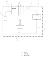
図1は、この発明の実施の形態1にかかる換気システムを備える住宅内ブロック構成図である。
図1を用いて、台所部に設置した換気システムの構成について説明する。建物内の一室としての台所1aの天井部にレンジフードファン等の換気装置2aが設置されている。換気装置2aには換気制御ユニット3が信号線4を介して接続されている。また、換気装置2aは壁リモコン21とも接続されている。
なお、台所1aにはIH加熱調理器等の調理器7や炊飯器8、食器洗浄機9が設置されている。調理器7はその電源プラグ71をコンセント52に接続することにより電源を得ている。炊飯器8、食器洗浄機9も同様である。コンセント52には商用交流電源5から分電盤50内の分岐ブレーカ51を経由して電源が供給される。また、分岐ブレーカ51部あるいはその付近に換気制御ユニット3の一部である情報収集手段としての電力センサ31が設置されている。なお、電力センサ31はコンセント52部に設置されていてもよい。
1 is a block diagram of an in-house block including a ventilation system according to
The structure of the ventilation system installed in the kitchen part will be described with reference to FIG. A ventilation device 2a such as a range hood fan is installed on the ceiling of a kitchen 1a as a room in the building. A
The kitchen 1a is provided with a
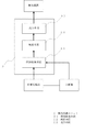
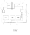
図2は、換気制御ユニット3のブロック構成図である。換気制御ユニット3は、調理器7等の電気機器の電力情報を分電盤50部あるいはコンセント52部から取得する情報収集手段31、その情報に基づいて換気装置2の運転モードを決定する判定手段32、その判定結果を動作指令として換気装置2に送出する出力手段33を備えている。情報収集手段31、判定手段32、出力手段33は通信用IC、マイコン等のハードウェアやそれらに搭載されたソフトウェアにより構成されている。
FIG. 2 is a block configuration diagram of the
次に、この発明の換気システムの動作について説明する。
まず、換気装置2aが運転を停止している状態の動作を説明する。調理器7を停止状態から使用開始したとする。それによって調理器7の接続されたコンセント52あるいは分岐ブレーカ51部の電力波形あるいは電力値が変化すると、それを電力センサ31が検出し、換気制御ユニット3内の判定手段32に送る。判定手段32は調理器7が運転開始したので調理時の臭いや煙、水蒸気が発生することを予測し、換気装置2aによる排気運転が必要だと判断する。その時点で換気装置2aは停止しているので、換気装置2aの運転を開始させる指令を出力手段33から信号線4を経由して換気装置2aに送信する。換気装置2aはその指令を受けて排気運転を開始する。
なお、調理器7の運転開始だけでなく、炊飯器8の動作や食器洗浄機9の動作によっても水蒸気等の発生が予測されるので、換気制御ユニット3は同様に電力波形あるいは電力値の変化によってそれらの電気機器の動作状況を取得し、換気装置2aの運転を開始させる指令を換気装置2aに送信する。
上記により、換気装置2aが運転を停止していても、調理器7や炊飯器8、食器洗浄機9等のいずれかが動作を開始し、臭いや煙、水蒸気の発生が予測される際には、換気制御ユニット3の指令により換気装置2aの排気運転を自動的に開始させることができる。
Next, the operation of the ventilation system of the present invention will be described.
First, the operation in a state where the ventilation device 2a is not operating will be described. It is assumed that use of the
In addition, since generation | occurrence | production of water vapor | steam etc. is estimated not only by the operation start of the
As described above, even when the ventilator 2a has stopped operating, when any of the
続いて、換気装置2aが排気運転を行っている状態での動作を説明する。調理器7のコンロ1台を使用しており、換気装置2aが風量弱で運転しているものとする。ここで、調理器7の別なコンロをさらに使い始めた場合、その情報は電力波形あるいは電力値の変化として換気制御ユニット3の電力センサ31から取り込まれる。電力センサ31はその情報を判定手段32に送り、判定手段32は調理器7の使用コンロ台数が増えたので調理時の臭いや煙、水蒸気が増加することを予測し、換気装置2aの排気風量を増やす必要があると判断する。その時点で換気装置2aは風量弱運転を実施しているので、風量を強に切り換える指令を出力手段33から信号線4を経由して換気装置2aに送信する。換気装置2aはその指令を受けて運転モードを風量弱から風量強に切り換えて運転する。
上記では調理器7の使用コンロ台数に対応し排気風量を増やす制御の例を示したが、対象となる電気機器を1台使用している状態から複数台使用する状態に変わった際に風量を増やす制御とすることもできる。また、上記では風量弱→風量強の例を示したが、風量弱→風量中、あるいは風量中→風量強であってもよい。また、風量は使用機器に対応して設定しておいてもいい。例えば、調理器7を使用開始した際は最大排気量である強を選択するように設定しておけばより適切な排気風量による自動運転が可能となる。
Subsequently, an operation in a state where the ventilation device 2a is performing the exhaust operation will be described. It is assumed that one stove of the
In the above, the example of the control for increasing the exhaust air volume corresponding to the number of the stove used for the
次に、換気制御ユニット3から換気装置への指令を送信する構成について説明する。
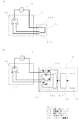
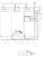
図3(a)は建物に既設の換気装置を簡単に示した構成図である。換気装置2のモータ20は商用交流電源5および壁リモコン21と配線接続されている。壁リモコン21には運転/停止スイッチ211、風量強/弱スイッチ212がある。運転/停止スイッチ211がON(運転)側に操作されると、商用交流電源5、運転/停止スイッチ211、風量強/弱スイッチ212、モータ20の閉回路が構成され、モータ20が起動してファン(図示せず)を回転させ、排気運転を開始する。このときの風量は風量強/弱スイッチ212の状態によって決まる。
Next, a configuration for transmitting a command from the
FIG. 3A is a configuration diagram simply showing an existing ventilation device in a building. The
図3(b)は上記のような既設の換気装置2に対し、換気制御ユニット3を接続して本実施の形態の換気システムの構成とする例を示す配線図である。壁リモコン21と商用交流電源5の一端およびモータ20の強ノッチ、弱ノッチとをそれぞれ接続していた配線を外し、商用交流電源5の一端を換気制御ユニット3の運転/停止リレー331の接点のNO端子(運転側)と接続、モータ20の強ノッチ、弱ノッチをそれぞれ換気制御ユニット3の風量強/弱リレー332の接点のNO端子(強側)、NC端子(弱側)と接続する。なお、運転/停止リレー331の接点のCOM端子と風量強/弱リレー332の接点のCOM端子とは換気制御ユニット3内で接続されている。また、運転/停止リレー331のコイルおよび風量強/弱リレー332のコイルは換気制御ユニット3内の出力リレー駆動部333に接続されている。運転/停止リレー331、風量強/弱リレー332および出力リレー駆動部333が換気制御ユニット3の出力手段33を構成している。
換気制御ユニット3は既設の換気装置2に対し、上記のように接続されるので、対象電気機器からの電力波形あるいは電力値の変化を受けた電力センサ31からの情報により判定手段32が決定した運転モードの指令を出力手段33の運転/停止リレー331あるいは風量強/弱リレー332の駆動により換気装置2に送信する。運転/停止リレー331、風量強/弱リレー332は壁リモコン21の運転/停止スイッチ211、風量強/弱スイッチ212と同一の構成で換気装置に接続されているので、対象電気機器の運転状況に応じた換気装置の自動運転を実現することができる。
FIG.3 (b) is a wiring diagram which shows the example which connects the
Since the
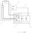
図4は、既設の換気装置に対し、換気制御ユニット3を接続して本実施の形態の換気システムの構成とする他の例を示す配線図である。換気装置2と換気制御ユニット3との接続は図3(b)に示した例と同じであるが、図4では、既設の壁リモコン21と換気制御ユニット3の情報収集手段31とを配線により接続している。すなわち、換気装置2との接続を外された既設の壁リモコン21のリモコン状態信号61を、新たな配線により換気制御ユニット3に送ることができる構成となっている。情報収集手段31が壁リモコン21の状態および対象電気機器の運転状態の両方を収集し、判定手段32がそれらの情報を総合的に判断して換気装置2の運転モードを決定する。例えば、壁リモコン21の状態と対象電気機器の運転状態とをORで判断することによって、手動運転と自動運転の両方が可能な換気システムが実現できる。なお、壁リモコン21と対象電気機器とに優先順位を設けることや別の条件を加味して運転モードを決定することも可能である。
FIG. 4 is a wiring diagram showing another example in which the
ここでは汎用の換気装置2に対し、換気制御ユニット3を配線によって本実施の形態の換気システムの構成とする例を示したが、換気制御ユニットの出力手段33をリレーではなく制御信号を送信する通信部とし、換気装置2側に受信部およびモータのON/OFFと風量の切り換えを行う制御部を設けることによって、換気制御ユニット3からの通信で換気装置2を制御する構成とすることも可能である。この場合の通信の方式は有線通信であっても無線通信であっても構わない。
Here, an example in which the
ところで、実施の形態1においては電気機器の運転状態を電力波形あるいは電力値の変化の検出により取得する例で説明したが、それ以外の方法で取得することも可能である。例えば、各電気機器の運転情報をHEMSコントローラ経由や各電気機器のリモコン装置経由で有線あるいは無線通信により取り込むことや各電気機器から直接有線あるいは無線通信により取り込むことも可能である。
また、調理器であれば温度センサにより温度上昇を検出したり、湿度センサにより湿度の増加を検出することで動作状態を認識することも可能である。さらに、臭いセンサや煙センサも有効である。炊飯器、食器洗浄機であれば湿度センサにより湿度の増加を検出することで動作状態を認識することができる。
なお、上記有線あるいは無線による各電気機器の運転情報の取り込み、あるいはセンサによる各電気機器周辺状況の取り込みの経路について、運転状態信号6として図1に模式的に示した。
なお、実施の形態1においては電気機器として調理器、炊飯器、食器洗浄機の例を上げたが、台所で使用するコーヒーメーカー、トースター、オーブンレンジ、電気ポット等も対象とすることができる。
また、実施の形態1においては換気装置の排気動作を取り上げて説明したが、排気と給気の両方を行うタイプの換気装置であっても本発明を適用することができる。
By the way, in
Moreover, if it is a cooking appliance, it is also possible to recognize an operation state by detecting a temperature rise with a temperature sensor or detecting an increase in humidity with a humidity sensor. Furthermore, odor sensors and smoke sensors are also effective. If it is a rice cooker and a dishwasher, an operation state can be recognized by detecting an increase in humidity with a humidity sensor.
Note that the
In the first embodiment, examples of a cooker, a rice cooker, and a dishwasher have been given as examples of electric devices. However, coffee makers, toasters, microwave ovens, electric kettles, and the like used in the kitchen can also be targeted.
In the first embodiment, the exhaust operation of the ventilator has been described. However, the present invention can also be applied to a ventilator that performs both exhaust and air supply.
実施の形態1では上記のように構成されているため、換気装置自体に専用の連動装置を備えずとも、建物内の機器と連動した自動換気運転が可能になる。また、連動する対象や連動する換気装置が任意に構成可能であり、より汎用性のある、かつ安価な換気システムが得られる。 Since the first embodiment is configured as described above, automatic ventilation operation linked to equipment in the building can be performed without providing a dedicated linkage device in the ventilation device itself. Further, the interlocking target and the interlocking ventilator can be arbitrarily configured, and a more versatile and inexpensive ventilation system can be obtained.
実施の形態2.
実施の形態1における換気システムでは、台所に設置された換気装置を台所で使用する各電気機器の運転状態に応じて自動運転させる例を示した。実施の形態2ではリビング等に設置された換気装置が掃除機の運転に応じて自動運転する例について説明する。
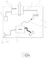
図5は、この発明の実施の形態2にかかる換気システムを備える住宅内ブロック図である。
図5を用いて、リビングに設置した換気システムの構成について説明する。建物内の一室としてのリビング1bの天井に居間用換気扇等の換気装置2bが設置されている。換気装置2bには換気制御ユニット3が信号線4を介して接続されている。また、換気装置2bは壁リモコン21とも接続されている。なお、リビング1b内のコンセント52部に換気制御ユニット3の情報収集手段としての電力センサが接続されているものとする(図示せず)。
In the ventilation system in
FIG. 5 is a block diagram in a house provided with a ventilation system according to
The configuration of the ventilation system installed in the living room will be described with reference to FIG. A ventilation device 2b such as a living room ventilation fan is installed on the ceiling of a living room 1b as a room in the building. A
次に、この発明の換気システムの動作について説明する。
まず、電気掃除機10を使っていない状態において、換気装置2bは停止状態だったとする。次に、リビング1b内のコンセント52に電気掃除機10の電源プラグ101を接続し、電気掃除機10の運転を開始すると、電力波形あるいは電力値の変化情報が換気制御ユニット3の電力センサによって取り込まれ、電力センサはその取得した情報を判定手段に送り、判定手段は電気掃除機10が運転開始したのでリビング1b内に軽量の塵埃が浮遊することを予測し、換気装置2bによる排気が必要だと判断する。その時点で換気装置2bは停止しているので、換気装置2bの運転を開始させる指令を信号線4を経由して換気装置2bに送信する。
上記により、換気装置2bが運転を停止していても、電気掃除機10が動作を開始し、塵埃の浮遊等の発生が予測される際には、換気制御ユニット3の指令により換気装置2bの排気運転を自動的に開始することができる。
Next, the operation of the ventilation system of the present invention will be described.
First, it is assumed that the ventilation device 2b is in a stopped state when the
As described above, even when the ventilation device 2b is not in operation, when the
また、換気装置2bがすでに運転している状態において電気掃除機10の運転を開始するような場合は、換気制御ユニット3は換気装置2bの排気風量を増やす指令を送信する。それによってリビング1b内に浮遊する塵埃をより確実に排気することが可能となる。
In addition, when the operation of the
なお、上記説明では換気制御ユニット3は電気掃除機10の運転状況を電力波形あるいは電力値の変化情報により取得したが、次に示す方法で取得してもよい。例えば、電気掃除機10の運転情報を電気掃除機10から無線信号により直接取り込んだり、HEMSコントローラ経由で取り込むことも可能である。
また、換気制御ユニット3の情報収集手段として音を検知するセンサ31を備えていてもよい。電気掃除機10が運転を開始するとモータの運転音や吸込み音が発生する。換気制御ユニット3は、その音を検知し、電気掃除機10が停止している静寂時の音のレベルと比較することによって電気掃除機10の運転開始を判断することができる。
なお、換気制御ユニット3と換気装置2bとの接続については、実施の形態1と同様であるため説明を省略する。
In the above description, the
Moreover, you may provide the sensor 31 which detects a sound as an information collection means of the
Since the connection between the
実施の形態2では上記のように構成されているため、実施の形態1同様、換気装置自体に専用の連動装置を備えずとも、建物内の機器と連動した自動換気運転が可能になる。また、連動する対象や連動する換気装置が任意に構成可能であり、より汎用性のある、かつ安価な換気システムが得られる。
また、音を検知するセンサを設けることによって、電気機器の動作状況を取得するための構成がより安価で簡単に実現可能となる。
Since the second embodiment is configured as described above, as in the first embodiment, automatic ventilation operation linked to equipment in the building can be performed even if the ventilation device itself is not provided with a dedicated linkage device. Further, the interlocking target and the interlocking ventilator can be arbitrarily configured, and a more versatile and inexpensive ventilation system can be obtained.
In addition, by providing a sensor for detecting sound, a configuration for acquiring the operation status of the electric device can be realized more inexpensively and easily.
実施の形態3.
実施の形態3における換気システムでは、洗濯乾燥機を設置している一室にある換気装置が洗濯乾燥機の運転に応じて自動運転する例について説明する。
図6は、この発明の実施の形態3にかかる換気システムを備える住宅内ブロック図である。
図6を用いて、例えば脱衣所に設置した換気システムの構成について説明する。建物の一室としての脱衣所1cの壁に換気扇等の換気装置2cが設置されている。換気装置2cには換気制御ユニット3が信号線4を介して接続されている。また、換気装置2cは壁リモコン21とも接続されている。なお、換気制御ユニット3と洗濯乾燥機11とは実施の形態1と同様にコンセントあるいは分電盤部の電力波形あるいは電力値の変化情報の取り込み(図示せず)あるいは無線通信等の運転状態信号6の取り込みにより接続されているものとする。
In the ventilation system according to the third embodiment, an example in which a ventilation device in one room in which a washing / drying machine is installed automatically operates according to the operation of the washing / drying machine will be described.
FIG. 6 is a block diagram in a house provided with a ventilation system according to
The structure of the ventilation system installed, for example in the dressing room is demonstrated using FIG. A ventilation device 2c such as a ventilation fan is installed on the wall of a dressing room 1c as a room of a building. A
次に、この発明の換気システムの動作について説明する。
まず、洗濯乾燥機11を使っていない状態において、換気装置2cは停止状態だったとする。次に、洗濯乾燥機11の運転を開始すると、その運転情報が電力波形あるいは電力値の変化情報として換気制御ユニット3の電力センサによって取り込まれ、電力センサはその取得した情報を判定手段に送り、判定手段は洗濯乾燥機11が運転開始したので脱衣所1c内の空気が高湿度になることを予測し、換気装置2cによる排気が必要だと判断する。その時点で換気装置2cは停止しているので、換気装置2cの運転を開始させる指令を信号線4を経由して換気装置2cに送信する。
上記により、換気装置2cが運転を停止していても、洗濯乾燥機11が動作を開始し、空気が高湿度になることが予測される際には、換気制御ユニット3の指令により換気装置2cの排気運転を自動的に開始することができる。
Next, the operation of the ventilation system of the present invention will be described.
First, it is assumed that the ventilation device 2c is in a stopped state when the washing / drying machine 11 is not used. Next, when the operation of the washing / drying machine 11 is started, the operation information is taken in by the power sensor of the
As described above, even when the ventilator 2c is not in operation, when the washing / drying machine 11 starts to operate and air is expected to become high humidity, the ventilator 2c is instructed by the command of the
また、換気装置2cがすでに運転している状態において洗濯乾燥機11の運転を開始するような場合は、換気制御ユニット3は換気装置2cの排気風量を増やす指令を送信する。それによって脱衣所1c内の高湿度空気をより確実に排気することが可能となる。
Further, when the operation of the washing / drying machine 11 is started in a state where the ventilation device 2c is already in operation, the
なお、上記説明では換気制御ユニット3は洗濯乾燥機11の運転状況を電力波形あるいは電力値の変化情報により取得したが、無線信号により直接取り込んだり、HEMSコントローラ経由で取り込むことも可能である。また、脱衣所1c内の湿度を検出するセンサを設け、高湿度を検出した際に洗濯乾燥機11の運転開始を判断してもよい。また、実施の形態2で示したような音の発生情報を取得し、それらに基づいて洗濯乾燥機11の運転開始を判断してもよい。
なお、換気制御ユニット3と換気装置2cとの接続については、実施の形態1と同様である。
In the above description, the
The connection between the
実施の形態3では上記のように構成されているため、実施の形態1同様、換気装置自体に専用の連動装置を備えずとも、建物内の機器と連動した自動換気運転が可能になる。また、連動する対象や連動する換気装置が任意に構成可能であり、より汎用性のある、かつ安価な換気システムが得られる。
また、湿度を検出するセンサを設けることによって、電気機器の動作状況を取得するための構成がより安価で簡単に実現可能となる。
Since the third embodiment is configured as described above, as in the first embodiment, automatic ventilation operation linked to equipment in the building can be performed without providing a dedicated interlocking device in the ventilation device itself. Further, the interlocking target and the interlocking ventilator can be arbitrarily configured, and a more versatile and inexpensive ventilation system can be obtained.
In addition, by providing a sensor for detecting humidity, a configuration for acquiring the operation status of the electric device can be realized more inexpensively and easily.
実施の形態4.
実施の形態4における換気システムでは、リビング等に設置された換気装置がエアコンや加湿機、除湿機等の空調機器の運転に応じて自動運転する例について説明する。
図7は、この発明の実施の形態4にかかる換気システムを備える住宅内ブロック図である。
図7を用いて、リビングに設置した換気システムの構成について説明する。建物の一室としてのリビング1bの天井に居間用換気扇等の換気装置2bが設置されている。換気装置2bには換気制御ユニット3が信号線4を介して接続されている。また、換気装置2bは壁リモコン21とも接続されている。なお、換気制御ユニット3と、エアコン12、加湿機13、除湿機14とは実施の形態1と同様にコンセントあるいは分電盤部の電力波形あるいは電力値の変化情報の取り込み(図示せず)あるいは無線通信等の運転状態信号6の取り込みにより接続されているものとする。
Embodiment 4 FIG.
In the ventilation system according to Embodiment 4, an example in which a ventilation device installed in a living room or the like automatically operates according to the operation of an air conditioner such as an air conditioner, a humidifier, or a dehumidifier will be described.
FIG. 7 is a block diagram in a house provided with a ventilation system according to Embodiment 4 of the present invention.
The structure of the ventilation system installed in the living room will be described with reference to FIG. A ventilation device 2b such as a living room ventilation fan is installed on the ceiling of the living room 1b as a room of the building. A
次に、この発明の換気システムの動作について説明する。
まず、エアコン12、加湿機13、除湿機14を使っていない状態において、換気装置2bが運転状態だったとする。次に、エアコン12、加湿機13、除湿機14のいずれかの運転を開始すると、その運転情報が電力波形あるいは電力値の変化情報として換気制御ユニット3の電力センサによって取り込まれ、電力センサはその取得した情報を判定手段に送り、判定手段はエアコン12、加湿機13、除湿機14等の空調機器のいずれかが運転を開始したのでリビング1b内が調和された快適な空気状態になることを予測し、換気装置2bによる排気を抑制する必要があると判断する。その時点で換気装置2bは運転しているので、換気装置2bの排気風量を減らす指令を信号線4を経由して換気装置2bに送信する。
上記により、換気装置2bが運転を実行していても、エアコン12、加湿機13、除湿機14等の空調機器が動作を開始し、空気が調和された快適な状態になることが予測される際には、換気制御ユニット3の指令により換気装置2bの排気風量を減らし、調和された快適な空気の排出を自動的に抑制することができる。なお、条件によっては排気風量を減らすのではなく換気装置2bを停止させてもよい。
Next, the operation of the ventilation system of the present invention will be described.
First, it is assumed that the ventilator 2b is in an operating state when the air conditioner 12, the humidifier 13, and the dehumidifier 14 are not used. Next, when any one of the air conditioner 12, the humidifier 13, and the dehumidifier 14 is started, the operation information is captured by the power sensor of the
From the above, even if the ventilation device 2b is operating, it is predicted that the air conditioners such as the air conditioner 12, the humidifier 13, and the dehumidifier 14 will start to operate, and the air is harmonized and comfortable. In this case, the exhaust air volume of the ventilator 2b can be reduced by the command of the
なお、上記説明では換気制御ユニット3はエアコン12、加湿機13、除湿機14等の空調機器の運転状況を電力波形あるいは電力値の変化情報によりにより取得したが、無線信号により直接取り込んだり、HEMSコントローラ経由で取り込むことも可能である。また、リビング1b内の温湿度を検出するセンサを設け、温湿度が快適な状態としてあらかじめ設定しておいた範囲内にある場合あるいはその範囲に向かって変化していることを検出した場合に各空調機器が運転状態あるいは運転を開始したと判断してもよい。
なお、換気制御ユニット3と換気装置2bとの接続については、実施の形態1と同様である。
In the above description, the
The connection between the
実施の形態4では上記のように構成されているため、実施の形態1同様、換気装置自体に専用の連動装置を備えずとも、建物内の機器と連動した自動換気運転が可能になる。また、連動する対象や連動する換気装置が任意に構成可能であり、より汎用性のある、かつ安価な換気システムが得られる。
また、温湿度を検出するセンサを設けることによって、空調機器の動作状況を取得するための構成がより安価で簡単に実現可能となる。
さらに、空調機器により調和された快適な空気の排出を抑制する動作を行うため、空調機器の運転負荷を軽減する省エネルギー効果も得られる。
Since the fourth embodiment is configured as described above, as in the first embodiment, automatic ventilation operation in conjunction with equipment in the building can be performed even if the ventilation device itself is not provided with a dedicated interlock device. Further, the interlocking target and the interlocking ventilator can be arbitrarily configured, and a more versatile and inexpensive ventilation system can be obtained.
Further, by providing a sensor for detecting the temperature and humidity, a configuration for acquiring the operation status of the air conditioner can be realized more inexpensively and easily.
Furthermore, since the operation | movement which suppresses the discharge | emission of the comfortable air harmonized with the air conditioner is performed, the energy saving effect which reduces the operation load of an air conditioner is also acquired.
実施の形態5.
実施の形態5における換気システムでは、浴室に設置された換気装置が給湯システムや浴室照明の運転に応じて自動運転する例について説明する。
図8は、この発明の実施の形態5にかかる換気システムを備える住宅内ブロック図である。
図8を用いて、浴室に設置した換気システムの構成について説明する。建物内の一室としての浴室1dの天井に浴室用換気扇等の換気装置2dが設置されている。換気装置2dには換気制御ユニット3が信号線4を介して接続されている。また、換気装置2dは壁リモコン21とも接続されている。換気制御ユニット3および壁リモコン21は脱衣所1c内に設置されているものとしたが、浴室1d内でも構わない。なお、換気制御ユニット3と、給湯システム16、浴室照明15とは実施の形態1と同様にコンセントあるいは分電盤部の電力波形あるいは電力値の変化情報の取り込み(図示せず)あるいは無線通信等の運転状態信号6の取り込みにより接続されているものとする。
In the ventilation system in the fifth embodiment, an example will be described in which a ventilation device installed in a bathroom automatically operates in accordance with the operation of a hot water supply system or bathroom lighting.
FIG. 8 is a block diagram in a house provided with a ventilation system according to
The configuration of the ventilation system installed in the bathroom will be described with reference to FIG. A
次に、この発明の換気システムの動作について説明する。
まず、給湯システム16、浴室照明15を使っていない状態において、換気装置2dが運転状態だったとする。次に、給湯システム16から浴槽161へのお湯張りの開始あるいは浴室照明15の点灯がなされると、その運転情報が電力波形あるいは電力値の変化情報として換気制御ユニット3の電力センサによって取り込まれ、電力センサはその取得した情報を判定手段に送り、判定手段は浴槽161へのお湯張りの開始や浴室照明15の点灯がなされたのでこれから居住者が入浴することを予測し、浴室1d内の暖められた空気を保つために換気装置2dによる排気を抑制する必要があると判断する。その時点で換気装置2dは運転しているので、換気装置2dの排気風量を減少させる指令を信号線4を経由して換気装置2dに送信する。
上記により、換気装置2dが運転を実行していても、給湯システム16、浴室照明15が動作を開始し、居住者の入浴が予測される際には、換気制御ユニット3の指令により換気装置2dの排気風量を減少させ、暖められた空気の排出を自動的に抑制することができる。なお、条件によっては排気風量を減らすのではなく換気装置2dを停止させてもよい。
Next, the operation of the ventilation system of the present invention will be described.
First, it is assumed that the
As described above, even when the
なお、上述した自動運転は外が寒い冬季において特に有効であるが、夏季には不要とする場合もあるので、判定手段がカレンダ機能を有し、設定された期間においてのみ上記自動運転を実行するように構成してもよい。
なお、上記説明では換気制御ユニット3は給湯システム16、浴室照明15の運転状況を電力波形あるいは電力値の変化情報によりにより取得したが、無線信号により直接取り込んだり、HEMSコントローラ経由で取り込むことも可能である。また、浴室1d内の温湿度を検出するセンサを設け、温度あるいは湿度が上昇している状況を検出した際に給湯システム16から浴槽161へのお湯張りが開始されたと判断してもよい。また、浴室1d内の明るさを検出するセンサを設け、暗い状態から明るい状態に変化した際に浴室照明15が点灯されたと判断してもよい。
なお、換気制御ユニット3と換気装置2dとの接続については、実施の形態1と同様である。
The automatic operation described above is particularly effective in the winter when it is cold outside, but may not be necessary in the summer, so the determination means has a calendar function and executes the automatic operation only during the set period. You may comprise as follows.
In the above description, the
The connection between the
実施の形態5では上記のように構成されているため、実施の形態1同様、換気装置自体に専用の連動装置を備えずとも、建物内の機器と連動した自動換気運転が可能になる。また、連動する対象や連動する換気装置が任意に構成可能であり、より汎用性のある、かつ安価な換気システムが得られる。
また、温湿度を検出するセンサや光を検知するセンサを設けることによって、浴室内の電気機器の運転状況すなわち浴室の使用状況を取得するための構成がより安価で簡単に実現可能となる。
さらに、お湯張りによって暖められた空気の排出を抑制する動作を行うため、入浴者が寒い浴室空間から浴槽の熱い湯の中に入ることによって気分が悪くなるような事態を未然に防止する効果も得られる。
Since the fifth embodiment is configured as described above, as in the first embodiment, automatic ventilation operation in conjunction with equipment in the building can be performed even if the ventilation device itself is not provided with a dedicated interlock device. Further, the interlocking target and the interlocking ventilator can be arbitrarily configured, and a more versatile and inexpensive ventilation system can be obtained.
In addition, by providing a sensor for detecting temperature and humidity and a sensor for detecting light, a configuration for acquiring the operating status of the electrical equipment in the bathroom, that is, the usage status of the bathroom, can be realized more inexpensively and easily.
In addition, since the operation to suppress the discharge of air warmed by hot water filling is performed, there is also an effect of preventing a situation where a bather feels uncomfortable by entering the hot water in the bathtub from a cold bathroom space can get.
実施の形態6.
実施の形態1〜5における換気システムでは、換気装置が対象とする電気機器の運転に応じて自動運転する例を示した。実施の形態6では対象電気機器の運転情報に加え、インターネット等の情報通信網を介して得られる情報等に基づいて換気装置が自動運転を行う例について説明する。
図9は、この発明の実施の形態6にかかる換気システムを備える住宅内ブロック図である。
図9を用いて、インターネットと接続した換気システムの構成について説明する。建物の一室としてのリビング1bの天井に居間用換気扇等の換気装置2bが設置されている。換気装置2bには換気制御ユニット3が信号線4を介して接続されている。また、換気装置2bは壁リモコン21とも接続されている。なお、リビング1b内のコンセント52部に換気制御ユニット3の情報収集手段としての電力センサが接続されているものとする(図示せず)。さらに、換気制御ユニット3はモデムやルーター(図示せず)を介して情報通信網であるインターネット17と接続されている。
In the ventilation system in Embodiment 1-5, the example which carries out automatic operation according to the driving | operation of the electric equipment which ventilation apparatus makes object was shown. In the sixth embodiment, an example will be described in which the ventilator performs automatic operation based on information obtained through an information communication network such as the Internet in addition to the operation information of the target electrical device.
FIG. 9 is a block diagram in a house including a ventilation system according to
The configuration of the ventilation system connected to the Internet will be described with reference to FIG. A ventilation device 2b such as a living room ventilation fan is installed on the ceiling of the living room 1b as a room of the building. A
次に、この発明の換気システムの動作について説明する。
実施の形態2で説明したように、換気制御ユニット3は電気掃除機10の運転開始情報を取得した際、停止状態にある換気装置2bの運転を開始させたり、風量弱で排気運転している換気装置2bを風量強の排気運転に切り換える等して室内に浮遊している塵埃を排出する運転を行うが、換気制御ユニット3の情報収集手段はインターネット17と接続されており、気象情報提供サイト171等から建物周辺の天気の状態等の気象情報を入手することが可能となっている。仮に、建物の周辺が雨天等で外気が高湿度だった場合、電気掃除機10の運転に応じて大風量で排気を行ったとすると、その排気に伴って高湿度の外気が建物内に侵入すると予想され、建物内が高湿度空気による不快な状態になってしまう。本実施の形態では、換気制御ユニット3がインターネット17により建物周辺の天気の状態を入手し、雨天あるいは高湿度である場合には換気装置2bに対し低風量の排気に抑えた運転指令を出力する。すなわち、電気掃除機10が運転を開始した際、換気装置2bが停止状態であれば排気運転を開始するものの風量は弱に止める。また、電気掃除機10が運転を開始した際、換気装置2bがすでに風量弱で排気運転している状態であれば風量強に切り換えることをせず風量弱のままの排気運転を継続する。
上記により、電気掃除機10が動作を開始しても、屋外が雨天あるいは高湿度の際には換気装置2bの排気風量を低く抑えるようにしたので、浮遊する塵埃を排出しつつ、湿気を帯びた外気の侵入を極力抑えるような排気運転を行うことができる。
Next, the operation of the ventilation system of the present invention will be described.
As described in the second embodiment, when the
As described above, even when the
なお、実施の形態5に示した換気装置2dによる換気システムの自動運転は、冬季の寒い時期における運転の際により効果的となるため、本実施の形態に示したようなインターネット17との接続により季節の判定あるいは外気温の判定を行って自動運転を実施するか否かを決定してもよい。
また、インターネット17による気象情報の収集に頼らず、屋外に別途設置した温湿度センサ等の出力を取り込んで判定してもよいが、インターネット17による気象情報の場合は現在の状況だけでなく数分後〜数時間後の状況が予測できるのでその状況に適した排気運転をあらかじめ行うことができるというメリットがある。
Note that the automatic operation of the ventilation system by the
In addition, it may be judged by taking in the output of a temperature / humidity sensor or the like separately installed outdoors without relying on the collection of weather information via the
実施の形態6では上記のように構成されているため、実施の形態1同様、換気装置自体に専用の連動装置を備えずとも、建物内の機器と連動した自動換気運転が可能になる。また、連動する対象や連動する換気装置が任意に構成可能であり、より汎用性のある、かつ安価な換気システムが得られる。
また、インターネットにより気象情報を収集することで屋外の状態に応じて電気機器の自動運転を調整するため、建物内の温湿度状態を適正に保ちつつ排気運転を行うことができる。
Since the sixth embodiment is configured as described above, as in the first embodiment, automatic ventilation operation linked to equipment in the building can be performed even if the ventilation device itself is not provided with a dedicated interlocking device. Further, the interlocking target and the interlocking ventilator can be arbitrarily configured, and a more versatile and inexpensive ventilation system can be obtained.
Further, by collecting weather information via the Internet, the automatic operation of the electric device is adjusted according to the outdoor state, so that the exhaust operation can be performed while keeping the temperature and humidity state in the building appropriate.
実施の形態7.
実施の形態1〜6における換気システムでは、ある一室に設置された換気装置がその一室における電気機器の運転に応じて自動運転する例を示した。実施の形態7では建物内の複数室あるいは建物の全室を対象範囲とし、その範囲での対象電気機器の運転情報によってその範囲に設置された換気装置が自動運転を行う例について説明する。
図10は、この発明の実施の形態7にかかる換気システムを備える住宅内ブロック図である。
図10を用いて、建物内に設置した換気システムの構成について説明する。建物内の部屋1eの天井に換気装置2e、部屋1fの天井に換気装置2f、部屋1gの天井に換気装置2gが設置されている。換気装置2e、2f、2gのそれぞれと換気制御ユニット3とが信号線4を介して接続されている。なお、部屋1e内のコンセント52e部、部屋1f内のコンセント52f部、部屋1g内のコンセント52g部あるいはそれらにつながる分電盤の各分岐ブレーカ51e、51f、51g付近に換気制御ユニット3の情報収集手段としての電力センサ31e、31f、31gが接続されているものとする。
In the ventilation system in Embodiment 1-6, the example which the ventilation apparatus installed in a certain room performs automatic operation according to the driving | operation of the electric equipment in the one room was shown. In the seventh embodiment, an example will be described in which a plurality of rooms in a building or all rooms in a building are set as a target range, and a ventilation device installed in the range performs automatic operation according to operation information of the target electrical equipment in that range.
FIG. 10: is a block diagram in a house provided with the ventilation
The structure of the ventilation system installed in the building will be described with reference to FIG. A ventilation device 2e is installed on the ceiling of the room 1e in the building, a ventilation device 2f is installed on the ceiling of the room 1f, and a ventilation device 2g is installed on the ceiling of the room 1g. Each of the ventilation devices 2e, 2f, and 2g and the
次に、この発明の換気システムの動作について説明する。
まず、電気掃除機10を部屋1fにて使う場合について説明する。部屋1fに設置された換気装置2fは停止状態だったとする。部屋1f内のコンセント52fに電気掃除機10の電源プラグ101を接続し、電気掃除機10の運転を開始すると、電力波形あるいは電力値の変化情報が換気制御ユニット3の電力センサ31fによって取り込まれ、電力センサ31fはその取得した情報を判定手段に送り、判定手段は電気掃除機10が運転開始したので部屋1f内に軽量の塵埃が浮遊することを予測し、換気装置2fによる排気が必要だと判断する。その時点で換気装置2fは停止しているので、換気装置2fの運転を開始させる指令を信号線4を経由して換気装置2fに送信する。
Next, the operation of the ventilation system of the present invention will be described.
First, the case where the
次に、電気掃除機10を部屋1fの隣の部屋1gに移動して運転を行なったとする。電気掃除機10を部屋1gに移動すなわち部屋1g内のコンセント52gに電気掃除機10の電源プラグ101を接続し直して運転しているという情報は換気制御ユニット3の電力センサ31gにより電力波形あるいは電力値の変化情報として取り込まれ、電力センサ31gはその取得した情報を判定手段に送り、判定手段はその情報に基づき、部屋1fに設置された換気装置2fの排気運転を停止し、部屋1gに設置された換気装置2gの排気運転を開始する。
上記のようにして、電気掃除機10が運転している一室に設置された換気装置が排気運転を行い、他室の換気装置は運転を停止するため、塵埃の浮遊等の発生が予測される一室の排気を自動的に行うことができる。また、電気掃除機10を使用していない一室の換気装置は自動的に停止されるので無駄な電力の消費を削減することができる。
また、換気装置がすでに運転している一室で電気掃除機10の運転を開始するような場合は、換気制御ユニット3は換気装置の排気風量を増やす指令を送信する。それによって一室内に浮遊する塵埃をより確実に排気することが可能となる。さらにその一室での電気掃除機10の運転が終了した際は、その一室の換気装置の排気風量を元の状態に戻して運転を継続するような制御も可能である。
なお、換気制御ユニット3と換気装置2e、2f、2gとの接続については、実施の形態1と同様であるため説明を省略する。
Next, it is assumed that the
As described above, the ventilation device installed in one room where the
When the operation of the
Since the connection between the
なお、上記説明では換気制御ユニット3は電気掃除機10の運転状況を電力波形あるいは電力値の変化情報により取得したが、実施の形態2に示したように情報収集手段として音を検知するセンサにより取得してもよい。センサが検知する音のレベルにより、電気掃除機10が換気制御ユニット3からどの程度離れた位置で運転しているのかを判定することにより、該当する部屋を推定してその部屋に設置された換気装置の運転を開始させる。
また、音を検知するセンサを換気制御ユニット本体部ではなく各室毎に設置して、それらの各センサから換気制御ユニットに情報送信するように構成すれば、電気掃除機10がどの室で運転しているかをより正確に検知することが可能となる。
また、電気掃除機10の運転情報を電気掃除機10から無線信号により直接取り込むことも可能である。この場合も、無線信号を受ける情報収集手段としての受信部を各室毎に設置して、それらの受信部から換気制御ユニットに情報送信するように構成すれば、電気掃除機10がどの室で運転しているかをより正確に検知することが可能となる。
In the above description, the
In addition, if a sensor for detecting sound is installed in each room instead of the ventilation control unit main body and information is transmitted from each sensor to the ventilation control unit, the
Moreover, it is also possible to take in the operation information of the
なお、実施の形態7では電気掃除機の例で説明したが、建物内に固定設置された各電気機器の動作に対し、それらの各電気機器付近の換気装置を自動排気運転させるような建物全体での換気システムの構築も可能である。 In the seventh embodiment, the example of the electric vacuum cleaner has been described. However, the entire building that automatically exhausts the ventilation device in the vicinity of each electric device in response to the operation of each electric device fixedly installed in the building. It is also possible to construct a ventilation system in
実施の形態7では上記のように構成されているため、実施の形態1同様、換気装置自体に専用の連動装置を備えずとも、建物内の機器と連動した自動換気運転が可能になる。また、連動する対象や連動する換気装置が任意に構成可能であり、より汎用性のある、かつ安価な換気システムが得られる。
また、電気機器が動作している部屋を認識し、その部屋の換気装置を自動運転させることができるので、建物全体において空気状態の改善や省エネルギーを図ることができる換気システムの構築が可能である。
Since the seventh embodiment is configured as described above, as in the first embodiment, automatic ventilation operation in conjunction with equipment in the building can be performed even if the ventilation device itself is not provided with a dedicated interlock device. Further, the interlocking target and the interlocking ventilator can be arbitrarily configured, and a more versatile and inexpensive ventilation system can be obtained.
In addition, it is possible to recognize the room in which the electrical equipment is operating and automatically operate the ventilation device in the room, so it is possible to construct a ventilation system that can improve the air condition and save energy in the entire building. .
2 換気装置
3 換気制御ユニット
31 情報収集手段
32 判定手段
33 出力手段
2
Claims (13)
外部情報を収集する情報収集手段と、前記外部情報に基づいて前記換気装置の運転モードを決定する判定手段と、前記換気装置に前記運転モードでの運転を指示する運転指令を送出する出力手段とを有する換気制御ユニットと、
を備えたことを特徴とする換気システム。 A ventilation device that is installed in the building and ventilates between the interior and the exterior of the building;
Information collecting means for collecting external information, determination means for determining an operation mode of the ventilator based on the external information, output means for sending an operation command for instructing the ventilator to operate in the operation mode, A ventilation control unit having
Ventilation system characterized by comprising
ことを特徴とする請求項1に記載の換気システム。 The ventilation system according to claim 1, wherein the external information collected by the information collecting unit is operating state information of an electric device installed indoors or outdoors in a building.
ことを特徴とする請求項2に記載の換気システム。 The ventilation system according to claim 2, wherein the information collecting unit includes a sensor for detecting electric power, and the operation state information is a change in an electric power waveform or an electric power value accompanying operation of the electric device.
ことを特徴とする請求項2に記載の換気システム。 The ventilation system according to claim 2, wherein the information collection unit includes a sensor that detects sound, and the operation state information is an operation sound of the electric device.
ことを特徴とする請求項1に記載の換気システム。 The ventilation system according to claim 1, wherein the information collecting unit includes a temperature sensor or a humidity sensor, and the external information is a temperature or humidity in a room where the ventilation device performs ventilation.
前記換気装置は前記建物の台所に設置された換気装置であり、
前記換気制御ユニットは、前記電気機器のいずれかが運転している場合には前記換気装置の運転モードを換気停止状態から換気運転状態に切り換える、あるいは換気風量が増加する側に切り換える
ことを特徴とする請求項2、3、5のいずれか一項に記載の換気システム。 The electrical device is a cooker or tableware dryer or rice cooker installed in the kitchen of the building,
The ventilator is a ventilator installed in the kitchen of the building;
The ventilation control unit switches the operation mode of the ventilator from a ventilation stop state to a ventilation operation state when one of the electrical devices is operating, or switches to a side where the ventilation air volume increases. The ventilation system according to any one of claims 2, 3, and 5.
前記換気装置は前記電気機器が存在する室内に設置された換気装置であり、
前記換気制御ユニットは、前記電気機器が運転している場合には前記換気装置の運転モードを換気停止状態から換気運転状態に切り換える、あるいは換気風量が増加する側に切り換える
ことを特徴とする請求項2〜4のいずれか一項に記載の換気システム。 The electrical device is a vacuum cleaner;
The ventilator is a ventilator installed in a room where the electrical equipment exists,
The ventilation control unit switches the operation mode of the ventilation device from a ventilation stop state to a ventilation operation state or switches to a side where the ventilation air volume increases when the electric device is operating. The ventilation system as described in any one of 2-4.
前記換気装置は前記電気機器が存在する室内に設置された換気装置であり、
前記換気制御ユニットは、前記電気機器が運転している場合には前記換気装置の運転モードを換気停止状態から換気運転状態に切り換える、あるいは換気風量が増加する側に切り換える
ことを特徴とする請求項2〜5のいずれか一項に記載の換気システム。 The electrical device is a washing dryer;
The ventilator is a ventilator installed in a room where the electrical equipment exists,
The ventilation control unit switches the operation mode of the ventilation device from a ventilation stop state to a ventilation operation state or switches to a side where the ventilation air volume increases when the electric device is operating. The ventilation system as described in any one of 2-5.
前記換気装置は前記電気機器が存在する室内に設置された換気装置であり、
前記換気制御ユニットは、前記電気機器が運転している場合には前記換気装置の運転モードを換気風量が減少する側に切り換える、あるいは換気運転状態から換気停止状態に切り換える
ことを特徴とする請求項2、3、5のいずれか一項に記載の換気システム。 The electric device is an air conditioner, a humidifier, or a dehumidifier,
The ventilator is a ventilator installed in a room where the electrical equipment exists,
The ventilation control unit is configured to switch the operation mode of the ventilation device to a side where the ventilation airflow decreases or switch from the ventilation operation state to the ventilation stop state when the electric device is operating. The ventilation system according to any one of 2, 3, and 5.
前記換気装置は浴室内に設置された換気装置であり、
前記換気制御ユニットは、前記電気機器が運転している場合には前記換気装置の運転モードを換気風量が減少する側に切り換える、あるいは換気運転状態から換気停止状態に切り換える
ことを特徴とする請求項2、3、5のいずれか一項に記載の換気システム。 The electrical device is a bathroom lighting or hot water supply system,
The ventilator is a ventilator installed in a bathroom,
The ventilation control unit is configured to switch the operation mode of the ventilation device to a side where the ventilation airflow decreases or switch from the ventilation operation state to the ventilation stop state when the electric device is operating. The ventilation system according to any one of 2, 3, and 5.
ことを特徴とする請求項1または2のいずれかに記載の換気システム。 The ventilation system according to claim 1 or 2, wherein the external information collected by the information collecting means includes weather data in the vicinity of the building obtained via the Internet.
外部情報を収集する情報収集手段と、前記外部情報に基づいて前記複数台の換気装置各々の運転モードを決定する判定手段と、前記複数台の換気装置各々に前記運転モードでの運転を指示する運転指令を送出する出力手段とを有する換気制御ユニットと、
を備えたことを特徴とする換気システム。 A plurality of ventilators installed in a building and ventilating between a plurality of indoors and outdoors in the building;
Information collecting means for collecting external information, determination means for determining the operation mode of each of the plurality of ventilators based on the external information, and instructing each of the plurality of ventilators to operate in the operation mode A ventilation control unit having output means for sending an operation command;
Ventilation system characterized by comprising
前記外部情報に基づいて換気装置の運転モードを決定する判定手段と、
前記換気装置に前記運転モードでの運転を指示する運転指令を送出する出力手段と
を備えたことを特徴とする換気制御ユニット。 An information collection means for collecting external information;
A determination means for determining an operation mode of the ventilator based on the external information;
A ventilation control unit comprising: output means for sending an operation command for instructing the ventilation device to operate in the operation mode.
Priority Applications (1)
| Application Number | Priority Date | Filing Date | Title |
|---|---|---|---|
| JP2016018552A JP2017138043A (en) | 2016-02-03 | 2016-02-03 | Ventilation system and ventilation control unit |
Applications Claiming Priority (1)
| Application Number | Priority Date | Filing Date | Title |
|---|---|---|---|
| JP2016018552A JP2017138043A (en) | 2016-02-03 | 2016-02-03 | Ventilation system and ventilation control unit |
Publications (1)
| Publication Number | Publication Date |
|---|---|
| JP2017138043A true JP2017138043A (en) | 2017-08-10 |
Family
ID=59565783
Family Applications (1)
| Application Number | Title | Priority Date | Filing Date |
|---|---|---|---|
| JP2016018552A Pending JP2017138043A (en) | 2016-02-03 | 2016-02-03 | Ventilation system and ventilation control unit |
Country Status (1)
| Country | Link |
|---|---|
| JP (1) | JP2017138043A (en) |
Cited By (3)
| Publication number | Priority date | Publication date | Assignee | Title |
|---|---|---|---|---|
| KR20190019497A (en) * | 2017-08-18 | 2019-02-27 | 주식회사 하츠 | automatic air circulation system |
| JP2019066120A (en) * | 2017-10-03 | 2019-04-25 | リンナイ株式会社 | Ventilation system |
| KR102106495B1 (en) * | 2018-11-16 | 2020-05-06 | 주식회사 가나테크 | Induction range hood system |
Citations (10)
| Publication number | Priority date | Publication date | Assignee | Title |
|---|---|---|---|---|
| JPH07280308A (en) * | 1994-04-04 | 1995-10-27 | Inax Corp | Control for ventilating fan in bathroom |
| JP2002209818A (en) * | 2001-01-19 | 2002-07-30 | Toshiba Tec Corp | Cleaning equipment |
| JP2002228214A (en) * | 2001-01-30 | 2002-08-14 | Osaka Gas Co Ltd | Ventilation interlocked controller |
| JP2002250548A (en) * | 2001-02-23 | 2002-09-06 | Rinnai Corp | Bathroom ventilation system |
| JP2004190866A (en) * | 2002-12-06 | 2004-07-08 | Max Co Ltd | Ventilator |
| JP2006145116A (en) * | 2004-11-19 | 2006-06-08 | Daikin Ind Ltd | Ventilation control device |
| JP2007032953A (en) * | 2005-07-28 | 2007-02-08 | Matsushita Electric Ind Co Ltd | Ventilation system and program thereof |
| JP2008190802A (en) * | 2007-02-06 | 2008-08-21 | Matsushita Electric Ind Co Ltd | Sanitary ventilation system |
| WO2011067988A1 (en) * | 2009-12-02 | 2011-06-09 | 日本電気株式会社 | Power measurement system, power measurement method, and information processing device |
| JP2012202626A (en) * | 2011-03-25 | 2012-10-22 | Azbil Corp | Ventilation control device and ventilation control method |
-
2016
- 2016-02-03 JP JP2016018552A patent/JP2017138043A/en active Pending
Patent Citations (10)
| Publication number | Priority date | Publication date | Assignee | Title |
|---|---|---|---|---|
| JPH07280308A (en) * | 1994-04-04 | 1995-10-27 | Inax Corp | Control for ventilating fan in bathroom |
| JP2002209818A (en) * | 2001-01-19 | 2002-07-30 | Toshiba Tec Corp | Cleaning equipment |
| JP2002228214A (en) * | 2001-01-30 | 2002-08-14 | Osaka Gas Co Ltd | Ventilation interlocked controller |
| JP2002250548A (en) * | 2001-02-23 | 2002-09-06 | Rinnai Corp | Bathroom ventilation system |
| JP2004190866A (en) * | 2002-12-06 | 2004-07-08 | Max Co Ltd | Ventilator |
| JP2006145116A (en) * | 2004-11-19 | 2006-06-08 | Daikin Ind Ltd | Ventilation control device |
| JP2007032953A (en) * | 2005-07-28 | 2007-02-08 | Matsushita Electric Ind Co Ltd | Ventilation system and program thereof |
| JP2008190802A (en) * | 2007-02-06 | 2008-08-21 | Matsushita Electric Ind Co Ltd | Sanitary ventilation system |
| WO2011067988A1 (en) * | 2009-12-02 | 2011-06-09 | 日本電気株式会社 | Power measurement system, power measurement method, and information processing device |
| JP2012202626A (en) * | 2011-03-25 | 2012-10-22 | Azbil Corp | Ventilation control device and ventilation control method |
Cited By (5)
| Publication number | Priority date | Publication date | Assignee | Title |
|---|---|---|---|---|
| KR20190019497A (en) * | 2017-08-18 | 2019-02-27 | 주식회사 하츠 | automatic air circulation system |
| KR102016020B1 (en) * | 2017-08-18 | 2019-08-29 | 주식회사 하츠 | automatic air circulation system |
| JP2019066120A (en) * | 2017-10-03 | 2019-04-25 | リンナイ株式会社 | Ventilation system |
| JP7033425B2 (en) | 2017-10-03 | 2022-03-10 | リンナイ株式会社 | Ventilation system |
| KR102106495B1 (en) * | 2018-11-16 | 2020-05-06 | 주식회사 가나테크 | Induction range hood system |
Similar Documents
| Publication | Publication Date | Title |
|---|---|---|
| US20070155305A1 (en) | Indoor air quality systems and methods | |
| CN114585861B (en) | Air change reporting device and storage device for air change reporting program | |
| CN111023475B (en) | Network system, server and information processing method | |
| JP6361667B2 (en) | Air conditioning system | |
| CN112944626B (en) | Air conditioner control method, device, air conditioner, storage medium and program product | |
| CN113091256A (en) | Air conditioner control method, air conditioner control device, air conditioner, storage medium and program product | |
| JP2017138043A (en) | Ventilation system and ventilation control unit | |
| JPWO2015190001A1 (en) | Air conditioning system | |
| JP2014202383A (en) | Air conditioning system | |
| CN107490124B (en) | Heating equipment and indoor ventilation detection method and detection device | |
| JP6454942B2 (en) | Control device, air environment control system, program, air environment control method | |
| JP6845754B2 (en) | Building air conditioning system | |
| JP2013181671A (en) | Air conditioner | |
| JPH05311956A (en) | Indoor ventilation system | |
| JP5698031B2 (en) | Building ventilation system | |
| CN119436380A (en) | Indoor environment adjustment method, device, electronic device and medium based on air conditioning | |
| KR102368815B1 (en) | Control method of air conditioner and air conditioner | |
| KR102335409B1 (en) | Control method of apparatus for air supply | |
| JPH08166159A (en) | Exhaust fan control system | |
| US4898086A (en) | Living space ventilation | |
| KR102260499B1 (en) | Control method of apparatus for air supply and indoors exhaust apparatus | |
| US20240344731A1 (en) | Multifunction adaptive fan system | |
| JP2003254570A (en) | Residential ventilation system | |
| KR100666233B1 (en) | Exhaust of the kitchen range hood | |
| JP6116442B2 (en) | Ventilation system and method for controlling ventilation system |
Legal Events
| Date | Code | Title | Description |
|---|---|---|---|
| A621 | Written request for application examination |
Free format text: JAPANESE INTERMEDIATE CODE: A621 Effective date: 20180507 |
|
| A977 | Report on retrieval |
Free format text: JAPANESE INTERMEDIATE CODE: A971007 Effective date: 20190215 |
|
| A131 | Notification of reasons for refusal |
Free format text: JAPANESE INTERMEDIATE CODE: A131 Effective date: 20190219 |
|
| A521 | Request for written amendment filed |
Free format text: JAPANESE INTERMEDIATE CODE: A523 Effective date: 20190408 |
|
| A131 | Notification of reasons for refusal |
Free format text: JAPANESE INTERMEDIATE CODE: A131 Effective date: 20190702 |
|
| A02 | Decision of refusal |
Free format text: JAPANESE INTERMEDIATE CODE: A02 Effective date: 20200107 |