JP2004190893A - Refrigerant storage container and refrigerant charging method - Google Patents
Refrigerant storage container and refrigerant charging method Download PDFInfo
- Publication number
- JP2004190893A JP2004190893A JP2002356830A JP2002356830A JP2004190893A JP 2004190893 A JP2004190893 A JP 2004190893A JP 2002356830 A JP2002356830 A JP 2002356830A JP 2002356830 A JP2002356830 A JP 2002356830A JP 2004190893 A JP2004190893 A JP 2004190893A
- Authority
- JP
- Japan
- Prior art keywords
- refrigerant
- pressure
- storage container
- container
- refrigeration cycle
- Prior art date
- Legal status (The legal status is an assumption and is not a legal conclusion. Google has not performed a legal analysis and makes no representation as to the accuracy of the status listed.)
- Pending
Links
Images
Classifications
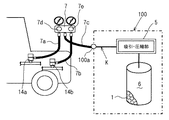
-
- F—MECHANICAL ENGINEERING; LIGHTING; HEATING; WEAPONS; BLASTING
- F25—REFRIGERATION OR COOLING; COMBINED HEATING AND REFRIGERATION SYSTEMS; HEAT PUMP SYSTEMS; MANUFACTURE OR STORAGE OF ICE; LIQUEFACTION SOLIDIFICATION OF GASES
- F25B—REFRIGERATION MACHINES, PLANTS OR SYSTEMS; COMBINED HEATING AND REFRIGERATION SYSTEMS; HEAT PUMP SYSTEMS
- F25B2309/00—Gas cycle refrigeration machines
- F25B2309/06—Compression machines, plants or systems characterised by the refrigerant being carbon dioxide
Landscapes
- Filling Or Discharging Of Gas Storage Vessels (AREA)
Abstract
【課題】耐圧強度の必要ない冷媒貯蔵容器6、およびそれを用いた冷媒充填方法を提供する。
【解決手段】容器6内に吸着剤1を詰めたうえ、容器6内に2気圧未満の圧力で冷媒を封入して貯蔵する。
これは、吸着剤1がガス冷媒を吸着保持するため、大気圧でも冷媒を貯蔵できることとなる。更に2気圧未満というのは、高圧ガス保安法の適用を受けない範囲であるため、この範囲で加圧することにより大気圧よりも吸着量を増やすことができる。
これにより、高圧ガス保安法の適用を受けないため、耐圧強度の必要ない安価な冷媒貯蔵容器6とすることができる。また、ガス入れ作業を習得した専任者以外でも取り扱うことができるうえ、使い終わった冷媒貯蔵容器6は通常の空き缶等と同様に処分することができるため、容器管理およびリサイクルのための新しいインフラ整備等は必要ない。
【選択図】 図1An object of the present invention is to provide a refrigerant storage container 6 that does not require pressure resistance, and a refrigerant charging method using the same.
A container is filled with an adsorbent, and a refrigerant is sealed and stored in the container at a pressure of less than 2 atm.
Since the adsorbent 1 adsorbs and holds the gas refrigerant, the refrigerant can be stored even at atmospheric pressure. Further, since the pressure of less than 2 atm is a range that is not subject to the application of the High Pressure Gas Safety Law, by applying pressure in this range, the adsorption amount can be increased more than the atmospheric pressure.
Thus, since the high-pressure gas safety law is not applied, it is possible to provide an inexpensive refrigerant storage container 6 that does not require pressure resistance. In addition, it can be handled by anyone other than the full-time expert who has learned gas filling work, and since the used refrigerant storage container 6 can be disposed of like a normal empty can, etc., a new infrastructure for container management and recycling is prepared. No such is necessary.
[Selection diagram] Fig. 1
Description
【0001】
【発明の属する技術分野】
本発明は、冷媒を貯蔵するための冷媒貯蔵容器と、その冷媒貯蔵容器から圧縮機、凝縮器、減圧装置および蒸発器を環状に接続した冷凍サイクルに冷媒を充填する場合の冷媒充填方法に関するものであり、特に、臨界温度の低いCO2等の冷媒の冷媒貯蔵容器および冷媒充填方法に関する。
【0002】
【従来の技術】
従来、臨界温度の高いフロン等の冷媒では、冷媒を貯蔵するための冷媒貯蔵容器としてボンベ等の高圧専用容器の他に高圧専用のサービス缶を設け、サービス工場等での冷媒の追加充填等に用いている。これらのサービス缶を含む高圧専用容器は高圧ガス保安法の適用を受けるため、前記法に準拠した取り扱いが必要となる。これは、臨界温度の低いCO2等の冷媒でも同様である。そして、使い終わったサービス缶は通常の空き缶と同様に処分している。
【0003】
【発明が解決しようとする課題】
しかしながら、臨界温度の低いCO2等の冷媒は、一般的使用条件において臨界圧力以上の高圧に圧縮して使用しているため、CO2冷媒等を用いた冷凍サイクルに冷媒を追加充填しようとすると、従来のフロン冷媒等の高圧専用容器よりも更に高圧で封入した冷媒貯蔵容器が必要となる。
【0004】
このような冷媒貯蔵容器は高価となるうえ、使い終わっても通常の空き缶と同様には処分できないため、容器管理およびリサイクルのための新しいインフラ整備が必要となる等の問題がある。本発明は、上記従来の問題に鑑みて成されたものであり、その目的は、耐圧強度の必要ない冷媒貯蔵容器、およびそれを用いた冷媒充填方法を提供することにある。
【0005】
【課題を解決するための手段】
上記目的を達成するために、請求項1ないし請求項4に記載の技術的手段を採用する。すなわち、請求項1に記載の発明では、容器(6)内に吸着剤(1)を詰めたうえ、容器(6)内に2気圧未満の圧力で冷媒を封入して貯蔵することを特徴とする。
【0006】
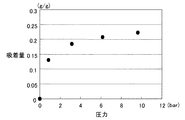
これは、吸着剤(1)がガス冷媒を吸着保持するため、大気圧でも冷媒を貯蔵できることとなる。更に2気圧未満というのは、高圧ガス保安法の適用を受けない範囲であるため、この範囲で加圧することにより大気圧よりも吸着量を増やすことができる(図4の圧力に対する吸着量の関係を表すグラフ参照)。
【0007】
これにより、高圧ガス保安法の適用を受けないため、耐圧強度の必要ない安価な冷媒貯蔵容器(6)とすることができる。また、ガス入れ作業を習得した専任者以外でも取り扱うことができるうえ、使い終わった冷媒貯蔵容器(6)は通常の空き缶等と同様に処分することができるため、容器管理およびリサイクルのための新しいインフラ整備等は必要ない。
【0008】
請求項2に記載の発明では、吸着剤(1)を粉末状にして容器(6)に詰めたことを特徴とする。これによっても吸着量(貯蔵量)を増やすことができる。
【0009】
請求項3に記載の発明では、冷媒はフロンガスよりも臨界温度の低い冷媒であることを特徴とする。これにより、従来高圧専用容器を用いて行なっていた臨界温度の低いCO2等の冷媒の貯蔵や供給を、簡易にすることができる。
【0010】
請求項4に記載の発明では、上記冷媒貯蔵容器(6)と、冷媒の圧縮機(10)、凝縮器(11)、減圧装置(12)、および蒸発器(13)を順に冷媒配管(14)で環状に接続された冷凍サイクル(R)と、冷媒貯蔵容器(6)から冷凍サイクル(R)へ冷媒を供給する供給路(K)と、供給路(K)の途中に吸引圧縮手段(5)とを設け、吸引圧縮手段(5)にて冷媒貯蔵容器(6)内の冷媒を吸引すると共に圧縮して冷凍サイクル(R)内に冷媒を充填することを特徴とする。
【0011】
これにより、大気圧近くの低圧で貯蔵している冷媒を、冷凍サイクル(R)に適正圧で充填することができる。尚、上記各手段の括弧内の符号は、後述する実施形態に記載の具体的手段との対応関係を示す一例である。
【0012】
【発明の実施の形態】
以下、本発明の実施形態を、図面に基づき説明する。図1は、本発明の一実施形態における冷媒貯蔵容器6および冷媒充填方法を示す模式図である。また、図2は、冷凍サイクルRの概略の構成を示す模式図である。本実施形態は、CO2冷媒を貯蔵するための冷媒貯蔵容器6と、CO2冷媒を用いた車両用空調装置の冷凍サイクルRに冷媒を追加充填する際の冷媒充填方法について説明する。
【0013】
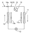
まず、図2に示すように、車両の冷凍サイクルRは、冷媒のコンプレッサ(圧縮機)10、コンデンサ(凝縮器)11、膨張弁(減圧装置)12、エバポレータ(蒸発器)13およびアキュムレータ15を順次冷媒配管14により接続して構成され、冷媒として臨界温度の低いCO2を使用している。
【0014】
コンプレッサ10は、共に図示しない車両走行用エンジンもしくは内蔵する電動モータによって駆動され、アキュムレータ15より吸引した冷媒を一般的使用条件において臨界圧力以上まで圧縮して吐出する。コンデンサ11は、コンプレッサ10より吐出された高圧のガス冷媒と送風機11aによって送風される外部空気(以下、外気)とを熱交換するもので、冷媒が流れる冷媒通路と、外気が流れる空気通路とを有し、冷媒の流れ方向と空気の流れ方向とが直交するように構成されている。
【0015】
しかし、コンデンサ11に流入するCO2冷媒は、コンプレッサ10で臨界圧力以上に加圧されているので、コンデンサ11で放熱しても凝縮することはない。膨張弁12は、コンデンサ11から流出する冷媒を弁開度に応じて減圧する減圧装置であり、制御装置(図示せず)によって弁開度が電気的に制御される。
【0016】
エバポレータ13は、膨張弁12で減圧された冷媒を送風機13aによって送風される外気もしくは車室内空気との熱交換によって蒸発させる。アキユムレータ15は、エバポレータ13で蒸発した冷媒を気液分離して液冷媒を貯留し、気相冷媒のみコンプレッサ10に吸引させ、サイクル中の余剰冷媒を蓄えておくものである。
【0017】
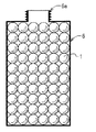
次に、本発明の要部の一つである冷媒貯蔵容器6の構成につき、図3を用いて説明する。図3は、本発明の一実施形態における冷媒貯蔵容器6を示す模式図である。鉄の缶の中にシリカゲルやゼオライト等を主成分とした吸着材1が詰めてある。但し、容器6は樹脂等であっても良い。
【0018】
また、図3では吸着材1を粒状で示したが、粒状やペレット状よりもより細かい粉末状にした方が吸着量を増やすことができる。そして、容器6内には大気圧、もしくは2気圧未満の圧力でCO2冷媒を吸着させ、封入して貯蔵してある。6aは、冷媒充填装置100に装着する時の接続部である。
【0019】
次に、本発明のもう一つの要部である冷媒充填方法について説明する。上記の冷媒貯蔵容器6を冷媒充填装置100にねじ込んで接続すると、図示しない針が冷媒貯蔵容器6の接続部6aの中央に刺さり、容器6の内部と冷凍サイクルRへ冷媒を供給する供給路Kとが連通するようになっている。そして、供給路Kの途中には冷媒貯蔵容器6内の冷媒を吸引すると共に圧縮して冷凍サイクルR内に充填する吸引圧縮部(吸引圧縮手段)5が設けられている。100aは冷凍サイクルR側と接続するためのジョイント部である。
【0020】
冷凍サイクルR側の接続部は、エバポレータ13とアキュムレータ15との間の冷媒配管14に低圧側サービスバルブ14aが配設されている(図2参照)。ちなみに14bは高圧側サービスバルブである。そして、ゲージマニホールド7で冷凍サイクルRと冷媒充填装置100とを接続する(図1参照)。尚、ゲージマニホールド7は冷凍サイクルの作動圧点検および真空引きや冷媒充填時に使用される器具である。
【0021】
具体的に、低圧チャージングホース7aを低圧側サービスバルブ14aに、高圧チャージングホース7bを高圧側サービスバルブ14bに、そしてセンターチャージングホース7cを冷媒充填装置100のジョイント100aに接続する。ちなみにこの時、ゲージマニホールド7の低圧バルブ7d・高圧バルブ7eおよび冷媒充填装置100の図示しないバルブは全て閉じた状態とする。
【0022】
次に、冷媒充填時にゲージマニホールド7の低圧バルブ7dを開いて冷凍サイクルRと冷媒充填装置100とを連通させる。そして、ゲージマニホールド7のゲージで検出される冷凍サイクルの圧力Pが適正冷媒量充填時の冷媒圧力Pnに到達するまで吸引圧縮部5で冷媒の圧縮充填を行なって冷媒の追加充填を終了する。
【0023】
次に、本実施形態での特徴を説明する。まず、容器6内に吸着剤1を詰めたうえ、容器6内に2気圧未満の圧力で冷媒を封入して貯蔵した。これは、吸着剤1がガス冷媒を吸着保持するため、大気圧でも冷媒を貯蔵できることとなる。更に2気圧未満というのは、高圧ガス保安法の適用を受けない範囲であるため、この範囲で加圧することにより大気圧よりも吸着量を増やすことができる。
【0024】
これにより、高圧ガス保安法の適用を受けないため、耐圧強度の必要ない安価な冷媒貯蔵容器6とすることができる。また、ガス入れ作業を習得した専任者以外でも取り扱うことができるうえ、使い終わった冷媒貯蔵容器6は通常の空き缶等と同様に処分することができるため、容器管理およびリサイクルのための新しいインフラ整備等は必要ない。
【0025】
また、吸着剤1を粉末状にして容器6に詰めている。これによっても吸着量(貯蔵量)を増やすことができる。また、冷媒はフロンガスよりも臨界温度の低い冷媒であることを特徴とする。これにより、従来高圧専用容器を用いて行なっていた臨界温度の低いCO2等の冷媒の貯蔵や供給を、簡易にすることができる。
【0026】
また、上記冷媒貯蔵容器6と、冷媒のコンプレッサ10、コンデンサ11、膨張弁12、およびエバポレータ13を順に冷媒配管14で環状に接続した冷凍サイクルRと、冷媒貯蔵容器6から冷凍サイクルRへ冷媒を供給する供給路Kと、供給路Kの途中に吸引圧縮部5とを設け、吸引圧縮部5にて冷媒貯蔵容器6内の冷媒を吸引すると共に圧縮して冷凍サイクルR内に冷媒を充填している。これにより、大気圧近くの低圧で貯蔵している冷媒を、冷凍サイクルRに適正圧で充填することができる。
【0027】
(その他の実施形態)
上述の実施形態では、車両用空調装置に対する冷媒の充填に本発明の冷媒充填方法を適用しているが、本発明はこれに限定されるものではなく、定置式の空調装置や給湯装置等冷媒を用いる冷凍サイクル全般の冷媒の充填に適用しても良い。また、冷媒もCO2に限らず、臨界温度の低いものであればエチレン・エタン・酸化窒素等の冷媒に適用しても良い。
【図面の簡単な説明】
【図1】本発明の一実施形態における冷媒貯蔵容器および冷媒充填方法を示す模式図である。
【図2】冷凍サイクルの概略の構成を示す模式図である。
【図3】本発明の一実施形態における冷媒貯蔵容器を示す模式図である。
【図4】圧力に対する吸着量の関係を表すグラフである。
【符号の説明】
1 吸着剤
5 吸引圧縮部(吸引圧縮手段)
6 冷媒貯蔵容器
10 コンプレッサ(圧縮機)
11 コンデンサ(凝縮器)
12 膨張弁(減圧装置)
13 エバポレータ(蒸発器)
14 冷媒配管
K 供給路
R 冷凍サイクル[0001]
TECHNICAL FIELD OF THE INVENTION
The present invention relates to a refrigerant storage container for storing a refrigerant, and to a refrigerant charging method for charging a refrigerant from the refrigerant storage container to a refrigeration cycle in which a compressor, a condenser, a decompression device, and an evaporator are connected in a ring shape. In particular, the present invention relates to a refrigerant storage container and a refrigerant charging method for a refrigerant such as CO 2 having a low critical temperature.
[0002]
[Prior art]
Conventionally, for refrigerants such as chlorofluorocarbon having a high critical temperature, a service canister for high pressure has been installed in addition to a high-pressure container such as a cylinder as a refrigerant storage container for storing the refrigerant, and used for additional charging of refrigerant at service factories and the like. Used. Since high-pressure containers including these service cans are subject to the High Pressure Gas Safety Law, they must be handled in accordance with the law. This is the same with a refrigerant such as CO 2 having a low critical temperature. The used service cans are disposed of like normal empty cans.
[0003]
[Problems to be solved by the invention]
However, since a refrigerant such as CO 2 having a low critical temperature is used after being compressed to a high pressure equal to or higher than the critical pressure under general use conditions, it is necessary to additionally charge the refrigerant to a refrigeration cycle using the CO 2 refrigerant or the like. In addition, a refrigerant storage container that is sealed at a higher pressure than a conventional high-pressure container such as a CFC refrigerant is required.
[0004]
Such a refrigerant storage container is expensive and cannot be disposed of in the same manner as a normal empty can when it has been used. Therefore, there is a problem that a new infrastructure for container management and recycling is required. The present invention has been made in view of the above-described conventional problems, and an object of the present invention is to provide a refrigerant storage container that does not require pressure resistance and a refrigerant charging method using the same.
[0005]
[Means for Solving the Problems]
In order to achieve the above object, the technical means described in claims 1 to 4 is adopted. That is, the invention according to claim 1 is characterized in that the container (6) is packed with the adsorbent (1), and the refrigerant is sealed and stored in the container (6) at a pressure of less than 2 atm. I do.
[0006]
Since the adsorbent (1) adsorbs and holds the gas refrigerant, the refrigerant can be stored even at atmospheric pressure. Further, the pressure less than 2 atm is a range in which the high pressure gas safety law is not applied. Therefore, by applying pressure in this range, the adsorption amount can be increased more than the atmospheric pressure (the relationship between the pressure and the adsorption amount in FIG. 4). ).
[0007]
Accordingly, since the high pressure gas safety law is not applied, an inexpensive refrigerant storage container (6) that does not require pressure resistance can be provided. In addition, since it can be handled by anyone other than the full-time expert who has learned gas filling work, the used refrigerant storage container (6) can be disposed of like a normal empty can, etc. No infrastructure development is required.
[0008]
The invention according to
[0009]
The invention according to claim 3 is characterized in that the refrigerant is a refrigerant having a lower critical temperature than Freon gas. Thereby, storage and supply of a refrigerant such as CO 2 having a low critical temperature, which has conventionally been performed using a high-pressure dedicated container, can be simplified.
[0010]
In the invention described in
[0011]
Thereby, the refrigerant stored at a low pressure near the atmospheric pressure can be charged into the refrigeration cycle (R) at an appropriate pressure. In addition, the code | symbol in the parenthesis of each said means is an example which shows the correspondence with the concrete means described in embodiment mentioned later.
[0012]
BEST MODE FOR CARRYING OUT THE INVENTION
Hereinafter, embodiments of the present invention will be described with reference to the drawings. FIG. 1 is a schematic diagram illustrating a
[0013]
First, as shown in FIG. 2, a refrigeration cycle R of a vehicle includes a refrigerant compressor (compressor) 10, a condenser (condenser) 11, an expansion valve (decompression device) 12, an evaporator (evaporator) 13, and an
[0014]
The
[0015]
However, since the CO 2 refrigerant flowing into the
[0016]
The
[0017]
Next, the configuration of the
[0018]
Although the adsorbent 1 is shown in a granular form in FIG. 3, it is possible to increase the amount of adsorption by making the adsorbent 1 finer than a granular form or a pellet form. In the
[0019]
Next, a refrigerant charging method, which is another main part of the present invention, will be described. When the above-mentioned
[0020]
In the connection portion on the refrigeration cycle R side, a low-pressure
[0021]
Specifically, the low
[0022]
Next, at the time of charging the refrigerant, the
[0023]
Next, features of the present embodiment will be described. First, the
[0024]
Thus, since the high-pressure gas safety law is not applied, it is possible to provide an inexpensive
[0025]
Further, the adsorbent 1 is powdered and packed in a
[0026]
Further, a refrigeration cycle R in which the
[0027]
(Other embodiments)
In the above-described embodiment, the refrigerant charging method of the present invention is applied to the charging of the refrigerant into the vehicle air conditioner, but the present invention is not limited to this, and the refrigerant such as a stationary air conditioner or a hot water supply device is used. The present invention may be applied to the charging of a refrigerant in the entire refrigeration cycle using the refrigerant. Further, the refrigerant is not limited to CO 2 , and may be applied to refrigerants such as ethylene, ethane, and nitrogen oxide as long as they have a low critical temperature.
[Brief description of the drawings]
FIG. 1 is a schematic diagram showing a refrigerant storage container and a refrigerant charging method according to an embodiment of the present invention.
FIG. 2 is a schematic diagram showing a schematic configuration of a refrigeration cycle.
FIG. 3 is a schematic diagram showing a refrigerant storage container according to an embodiment of the present invention.
FIG. 4 is a graph showing a relationship between an adsorption amount and a pressure.
[Explanation of symbols]
1 adsorbent 5 suction compression part (suction compression means)
6
11 Condenser (condenser)
12 Expansion valve (pressure reducing device)
13. Evaporator (evaporator)
14 Refrigerant pipe K Supply path R Refrigeration cycle
Claims (4)
冷媒の圧縮機(10)、凝縮器(11)、減圧装置(12)、および蒸発器(13)を順に冷媒配管(14)で環状に接続した冷凍サイクル(R)と、
前記冷媒貯蔵容器(6)から前記冷凍サイクル(R)へ冷媒を供給する供給路(K)と、
前記供給路(K)の途中に吸引圧縮手段(5)とを設け、
前記吸引圧縮手段(5)にて前記冷媒貯蔵容器(6)内の冷媒を吸引すると共に圧縮して前記冷凍サイクル(R)内に冷媒を充填することを特徴とする冷媒充填方法。A refrigerant storage container (6) according to any one of claims 1 to 3,
A refrigeration cycle (R) in which a refrigerant compressor (10), a condenser (11), a pressure reducing device (12), and an evaporator (13) are sequentially connected in an annular manner by a refrigerant pipe (14);
A supply path (K) for supplying a refrigerant from the refrigerant storage container (6) to the refrigeration cycle (R);
A suction compression means (5) is provided in the middle of the supply path (K),
A refrigerant charging method, wherein the refrigerant in the refrigerant storage container (6) is sucked and compressed by the suction compression means (5) to fill the refrigerant in the refrigeration cycle (R).
Priority Applications (1)
| Application Number | Priority Date | Filing Date | Title |
|---|---|---|---|
| JP2002356830A JP2004190893A (en) | 2002-12-09 | 2002-12-09 | Refrigerant storage container and refrigerant charging method |
Applications Claiming Priority (1)
| Application Number | Priority Date | Filing Date | Title |
|---|---|---|---|
| JP2002356830A JP2004190893A (en) | 2002-12-09 | 2002-12-09 | Refrigerant storage container and refrigerant charging method |
Publications (1)
| Publication Number | Publication Date |
|---|---|
| JP2004190893A true JP2004190893A (en) | 2004-07-08 |
Family
ID=32757055
Family Applications (1)
| Application Number | Title | Priority Date | Filing Date |
|---|---|---|---|
| JP2002356830A Pending JP2004190893A (en) | 2002-12-09 | 2002-12-09 | Refrigerant storage container and refrigerant charging method |
Country Status (1)
| Country | Link |
|---|---|
| JP (1) | JP2004190893A (en) |
Cited By (1)
| Publication number | Priority date | Publication date | Assignee | Title |
|---|---|---|---|---|
| CN105716199A (en) * | 2016-02-06 | 2016-06-29 | 王圣泉 | Air-conditioning pressure automatic adjustment device and method |
-
2002
- 2002-12-09 JP JP2002356830A patent/JP2004190893A/en active Pending
Cited By (2)
| Publication number | Priority date | Publication date | Assignee | Title |
|---|---|---|---|---|
| CN105716199A (en) * | 2016-02-06 | 2016-06-29 | 王圣泉 | Air-conditioning pressure automatic adjustment device and method |
| CN105716199B (en) * | 2016-02-06 | 2019-01-04 | 王圣泉 | Automatic air conditioner pressure adjusting device and method |
Similar Documents
| Publication | Publication Date | Title |
|---|---|---|
| US5392610A (en) | Method and apparatus for recovering refrigerants from home refrigeration systems | |
| US6722141B2 (en) | Apparatus and methods for placing an additive fluid into a refrigerant circuit | |
| US6449962B1 (en) | Refrigerant collecting device, refrigerant collecting method, refrigerator having refrigerant collecting device, control method for refrigerant in refrigerant circuit or regeneration device and regeneration method for refrigerant collecting | |
| JP3501678B2 (en) | Storage, transportation and installation of air conditioners | |
| JP2002195705A (en) | Supercritical refrigerating cycle | |
| CN110454682A (en) | A gas compressor system for filling a container with gas | |
| JP2011237146A (en) | Air conditioner | |
| JP2004190893A (en) | Refrigerant storage container and refrigerant charging method | |
| JP2984812B2 (en) | Method and apparatus for filling compressed fuel gas into cylinder | |
| JP2001071741A (en) | Air conditioning device for vehicle | |
| CN101504112A (en) | Hydrogen fueling | |
| JP4100904B2 (en) | Two-stage compression refrigeration system, refrigerating machine oil and refrigerant charging method | |
| JPH06101940A (en) | Sealing of refrigerant | |
| JPH08210736A (en) | Non-azeotrope refrigerant filling system and filling method | |
| JPH08152230A (en) | Separate type air conditioner | |
| JP2004190894A (en) | Refrigerant cycle refrigerant charging method and refrigerant charging device | |
| JP2002147903A (en) | Method and apparatus for recovering refrigerant of air conditioner | |
| JPH10141814A (en) | Refrigeration cycle air removal equipment | |
| JP2002090008A (en) | Method and apparatus for charging refrigerant in refrigeration cycle | |
| CN223783097U (en) | A test device for a split-type pure electric refrigerator | |
| JP4749158B2 (en) | Repair method of refrigerant circuit filled with carbon dioxide as refrigerant | |
| JPH03164673A (en) | Refrigerant recovering and charging device for air conditioner | |
| JP4393626B2 (en) | Gas system system poison prevention device | |
| US20250012477A1 (en) | Air conditioning unit and packaging unit | |
| JPH09250849A (en) | Bomb for temporary storage of refrigerant gas and its application method |