JP2004200364A - Exhaust gas treatment device and exhaust gas treatment method - Google Patents
Exhaust gas treatment device and exhaust gas treatment method Download PDFInfo
- Publication number
- JP2004200364A JP2004200364A JP2002366431A JP2002366431A JP2004200364A JP 2004200364 A JP2004200364 A JP 2004200364A JP 2002366431 A JP2002366431 A JP 2002366431A JP 2002366431 A JP2002366431 A JP 2002366431A JP 2004200364 A JP2004200364 A JP 2004200364A
- Authority
- JP
- Japan
- Prior art keywords
- gas
- exhaust pipe
- process gas
- vacuum pump
- heated
- Prior art date
- Legal status (The legal status is an assumption and is not a legal conclusion. Google has not performed a legal analysis and makes no representation as to the accuracy of the status listed.)
- Pending
Links
- 238000000034 method Methods 0.000 title claims abstract description 80
- 239000007789 gas Substances 0.000 claims abstract description 136
- IJGRMHOSHXDMSA-UHFFFAOYSA-N Atomic nitrogen Chemical compound N#N IJGRMHOSHXDMSA-UHFFFAOYSA-N 0.000 claims abstract description 49
- 229910001873 dinitrogen Inorganic materials 0.000 claims abstract description 49
- 238000010790 dilution Methods 0.000 claims abstract description 5
- 239000012895 dilution Substances 0.000 claims abstract description 5
- 238000010438 heat treatment Methods 0.000 claims description 29
- 238000007865 diluting Methods 0.000 claims description 3
- 238000002485 combustion reaction Methods 0.000 abstract description 23
- 239000007795 chemical reaction product Substances 0.000 abstract description 14
- 230000000694 effects Effects 0.000 abstract description 9
- 238000010586 diagram Methods 0.000 abstract description 7
- 230000020169 heat generation Effects 0.000 abstract 1
- 238000004519 manufacturing process Methods 0.000 description 6
- 239000004065 semiconductor Substances 0.000 description 6
- 238000012423 maintenance Methods 0.000 description 5
- 238000001312 dry etching Methods 0.000 description 1
- 239000002184 metal Substances 0.000 description 1
- 239000012495 reaction gas Substances 0.000 description 1
Images


Landscapes
- Incineration Of Waste (AREA)
Abstract
【課題】ガス排気配管内への反応生成物の付着抑止効果を向上させる。
【解決手段】窒素ガスを輸送するN2ガス配管5を燃焼室2の外周に巻き付け、燃焼室2の発熱により加熱された窒素ガスを真空ポンプ3の希釈ガスとして真空ポンプ3内に送るとともに、プロセスガス排気管7内に送る。
【選択図】 図1An object of the present invention is to improve the effect of preventing reaction products from adhering to a gas exhaust pipe.
An N 2 gas pipe (5) for transporting nitrogen gas is wound around the outer periphery of a combustion chamber (2), and nitrogen gas heated by heat generation in the combustion chamber (2) is sent into the vacuum pump (3) as a dilution gas of the vacuum pump (3). It is sent into the process gas exhaust pipe 7.
[Selection diagram] Fig. 1
Description
【0001】
【発明の属する技術分野】
本発明は排ガス処理装置および排ガス処理方法に関し、特に、燃焼式除害装置または加熱式除害装置を持つ半導体製造装置に適用して好適なものである。
【0002】
【従来の技術】
従来の排ガス処理装置では、半導体製造装置から排出される熱排気を利用して、ガス排気配管を加熱することにより、ガス排気配管内に反応生成物が付着することを抑える方法があった。
図3は、従来の排ガス処理装置の概略構成を示すブロック図である。
【0003】
図3において、半導体製造装置22にはチャンバ23が設けられ、チャンバ23内には、反応ガスが導入されて、CVDやドライエッチングなどのプロセスが行われる。
そして、チャンバ23から排出された排ガスは、ガス排気配管24を介して除害装置21に導入され、除害装置21にて、チャンバ23から排出された排ガスの除害処理が行われる。
【0004】
ここで、半導体製造装置22には熱排気管25が設けられ、熱排気管25は、ガス排気配管24の外周を覆うように構成されている。
そして、半導体製造装置から排出される熱排気は熱排気管25に排出され、ガス排気配管24の外周を通ってガス排気配管24を加熱した後、外部に排気される。
【0005】
そして、ガス排気配管24を加熱することにより、チャンバ23から排出された排ガスがガス排気配管24内で暖められ、ガス排気配管24内への反応生成物の付着を抑制することが可能となる。
【0006】
【発明が解決しようとする課題】
しかしながら、従来の排ガス処理装置では、半導体製造装置22から排出される熱排気を利用して、ガス排気配管24の周囲を加熱するため、排ガスの加熱効果が必ずしも十分でなく、ガス排気配管24内への反応生成物の付着を必ずしも十分に抑えることができないという問題があった。
【0007】
そこで、本発明の目的は、ガス排気配管内への反応生成物の付着抑止効果を向上させることが可能な排ガス処理装置および排ガス処理方法を提供することである。
【0008】
【課題を解決するための手段】
上述した課題を解決するために、請求項1記載の排ガス処理装置によれば、熱源を有する除害装置と、前記熱源から生じる発熱を利用して、窒素ガスを加熱する加熱手段と、前記加熱された窒素ガスで希釈を行いつつ、プロセスガスを排気する真空ポンプと、前記真空ポンプで排気されたプロセスガスを前記除害装置に導入する排気管とを備えることを特徴とする。
【0009】
これにより、除害装置から生じる発熱を利用して、窒素ガスを加熱することが可能となり、除害装置から生じる発熱を有効利用することが可能となるとともに、加熱された窒素ガスを希釈ガスとして用いつつ、加熱された窒素ガスで排気管内を直接加熱することが可能となる。
このため、省エネルギー化を図りつつ、排気管内への反応生成物の付着抑止効果を向上させることが可能となり、排気管内の詰まりによるトラブルや排気管内のメンテナンスなどを削減することが可能となる。
【0010】
また、請求項2記載の排ガス処理装置によれば、熱源を有する除害装置と、前記熱源から生じる発熱を利用して、プロセスガスおよび窒素ガスを加熱する加熱手段と、前記加熱された窒素ガスで希釈を行いつつ、前記加熱されたプロセスガスを排気する真空ポンプと、前記真空ポンプで排気されたプロセスガスを前記除害装置に導入する排気管とを備えることを特徴とする。
【0011】
これにより、除害装置から生じる発熱を利用して、窒素ガスのみならず、プロセスガスも加熱することが可能となり、除害装置から生じる発熱の有効利用を図りつつ、排気管内への反応生成物の付着抑止効果を向上させることが可能となることから、排気管内の詰まりによるトラブルや排気管内のメンテナンスなどを削減することが可能となる。
【0012】
また、請求項3記載の排ガス処理装置によれば、熱源を有する除害装置と、前記熱源から生じる発熱を利用して、窒素ガスを加熱する加熱手段と、プロセスガスを排気する真空ポンプと、前記真空ポンプで排気されたプロセスガスを前記除害装置に導入する排気管と、前記加熱手段で加熱された窒素ガスを前記排気管に導入する導入管とを備えることを特徴とする。
【0013】
これにより、除害装置から生じる発熱の有効利用を図りつつ、加熱された窒素ガスで排気管内を直接加熱することが可能となり、省エネルギー化を図りつつ、排気管内への反応生成物の付着抑止効果を向上させることが可能となる。
また、請求項4記載の排ガス処理装置によれば、熱源を有する除害装置と、前記熱源から生じる発熱を利用して、プロセスガスおよび窒素ガスを加熱する加熱手段と、前記加熱されたプロセスガスプロセスガスを排気する真空ポンプと、前記真空ポンプで排気されたプロセスガスを前記除害装置に導入する排気管と、前記加熱手段で加熱された窒素ガスを前記排気管に導入する導入管とを備えることを特徴とする。
【0014】
これにより、除害装置から生じる発熱の有効利用を図りつつ、窒素ガスのみならず、プロセスガスも加熱することが可能となり、省エネルギー化を図りつつ、排気管内への反応生成物の付着抑止効果をより一層向上させることが可能となる。
また、請求項5記載の排ガス処理方法によれば、除害装置から生じる発熱を利用して、窒素ガスを加熱するステップと、前記加熱された窒素ガスを真空ポンプまたは前記真空ポンプの排気管に導入しながら、プロセスガスの排気を行うステップと、前記排気されたプロセスガスを前記除害装置で除害するステップとを備えることを特徴とする。
【0015】
これにより、除害装置から生じる発熱の有効利用を図りつつ、加熱された窒素ガスで排気管内を直接加熱することが可能となり、省エネルギー化を図りつつ、排気管内への反応生成物の付着抑止効果を向上させることが可能となる。
また、請求項6記載の排ガス処理方法によれば、除害装置から生じる発熱を利用して、プロセスガスおよび窒素ガスを加熱するステップと、前記加熱された窒素ガスを真空ポンプまたは前記真空ポンプの排気管に導入しながら、前記加熱されたプロセスガスの排気を行うステップと、前記排気されたプロセスガスを前記除害装置で除害するステップとを備えることを特徴とする。
【0016】
これにより、除害装置から生じる発熱の有効利用を図りつつ、窒素ガスのみならず、プロセスガスも加熱することが可能となり、省エネルギー化を図りつつ、排気管内への反応生成物の付着抑止効果をより一層向上させることが可能となる。
【0017】
【発明の実施の形態】
以下、本発明の実施形態に係る排ガス処理装置について、図面を参照しながら説明する。
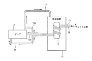
図1は、本発明の第1実施形態に係る排ガス処理装置の概略構成を示すブロック図である。
【0018】
図1において、燃焼式除害装置1には、除害ガスを燃焼させる燃焼室2が設けられ、真空ポンプ3の吸気側にはプロセスガス吸気管6が連結されるとともに、真空ポンプ3の排気側にはプロセスガス排気管7が連結され、プロセスガス排気管7は燃焼室2に連結されている。
また、窒素ガスを輸送するN2ガス配管5が燃焼室2の外周に巻き付けられるとともに、N2ガス分岐管5a、5bにより分岐され、N2ガス分岐管5aは真空ポンプ3に連結されるとともに、N2ガス分岐管5bはプロセスガス排気管7の入口側に連結されている。
【0019】
そして、プロセスガス吸気管6を介して真空ポンプ3に吸引されたプロセス排気は、プロセスガス排気管7を介して燃焼室2内に送られ、燃焼室2にてプロセスガスが燃焼される。
一方、N2ガス配管5に送出された窒素ガスは燃焼室2からの発熱により加熱され、加熱された窒素ガスの一部は、N2ガス分岐管5aを介して、真空ポンプ3の希釈ガスとして真空ポンプ3内に送られるとともに、加熱された窒素ガスの残りは、N2ガス分岐管5bを介して、プロセスガス排気管7内に送られる。
【0020】
そして、真空ポンプ3およびプロセスガス排気管7内に送られた窒素ガスは、プロセスガス排気管7内を通ることにより、プロセスガス排気管7内を加熱する。
これにより、燃焼室2から放出される発熱を利用して、窒素ガスを加熱することが可能となるとともに、加熱された窒素ガスを用いて、プロセスガス排気管7内を直接加熱することが可能となる。
【0021】
このため、省エネルギー化を図りつつ、プロセスガス排気管7内への反応生成物の付着抑止効果を向上させることが可能となり、プロセスガス排気管7内の詰まりによるトラブルやプロセスガス排気管7内のメンテナンスなどを削減することが可能となる。
図2は、本発明の第2実施形態に係る排ガス処理装置の概略構成を示すブロック図である。
【0022】
図2において、燃焼式除害装置11には、除害ガスを燃焼させる燃焼室12が設けられ、真空ポンプ13の排気側にはプロセスガス排気管17が連結されるとともに、プロセスガス排気管17は燃焼室12に連結されている。
また、窒素ガスを輸送するN2ガス配管15が燃焼室12の外周に巻き付けられるとともに、N2ガス分岐管15a、15bにより分岐され、N2ガス分岐管15aは真空ポンプ13に連結されるとともに、N2ガス分岐管15bはプロセスガス排気管17の入口側に連結されている。
【0023】
さらに、プロセスガス吸気管16は、燃焼室12の外周に巻き付けられ、真空ポンプ13の吸気側に連結されている。
そして、プロセスガス吸気管16に送出されたプロセス排気は、プロセスガス吸気管16を介して加熱された後、真空ポンプ13に吸引され、プロセスガス排気管17を介して燃焼室12内に送られ、燃焼室12にてプロセスガスが燃焼される。
【0024】
一方、N2ガス配管15に送出された窒素ガスは燃焼室12からの発熱により加熱され、加熱された窒素ガスの一部は、N2ガス分岐管15aを介して、真空ポンプ13の希釈ガスとして真空ポンプ13内に送られるとともに、加熱された窒素ガスの残りは、N2ガス分岐管15bを介して、プロセスガス排気管17内に送られる。
【0025】
そして、真空ポンプ13およびプロセスガス排気管17内に送られた窒素ガスおよびプロセスガスは、プロセスガス排気管17内を通ることにより、プロセスガス排気管17内を加熱する。
これにより、燃焼室12から放出される発熱を利用して、窒素ガスのみならず、プロセスガスも加熱することが可能となるとともに、加熱された窒素ガスおよびプロセスガスを用いて、プロセスガス排気管17内を直接加熱することが可能となる。
【0026】
このため、省エネルギー化を図りつつ、プロセスガス排気管17内への反応生成物の付着抑止効果をより一層向上させることが可能となり、プロセスガス排気管17内の詰まりによるトラブルやプロセスガス排気管17内のメンテナンスなどを削減することが可能となる。
なお、上述した実施形態では、燃焼式除害装置を例にとって説明したが、発熱源を有する除害装置なら何でもよく、例えば、ヒータ加熱式除害装置を用いるようにしてもよい。
【0027】
【発明の効果】
以上説明したように、本発明によれば、除害装置から生じる発熱を利用して加熱された窒素ガスを用いて、排気管内を直接加熱することにより、省エネルギー化を図りつつ、排気管内への反応生成物の付着抑止効果を向上させることが可能となり、排気管内の詰まりによるトラブルや排気管内のメンテナンスなどを削減することが可能となる。
【図面の簡単な説明】
【図1】本発明の第1実施形態に係る排ガス処理装置の概略構成を示すブロック図である。
【図2】本発明の第2実施形態に係る排ガス処理装置の概略構成を示すブロック図である。
【図3】従来の排ガス処理装置の概略構成を示すブロック図である。
【符号の説明】
1、11 燃焼式除害装置、2、12 燃焼室、3、13 真空ポンプ、5、15 N2ガス配管、5a、5b、15a、15b N2ガス分岐管 6、16 プロセスガス吸気管、7、17 プロセスガス排気管[0001]
TECHNICAL FIELD OF THE INVENTION
The present invention relates to an exhaust gas treatment apparatus and an exhaust gas treatment method, and is particularly suitable for application to a semiconductor manufacturing apparatus having a combustion type abatement apparatus or a heating type abatement apparatus.
[0002]
[Prior art]
In a conventional exhaust gas treatment apparatus, there is a method in which heat exhaust gas discharged from a semiconductor manufacturing apparatus is used to heat a gas exhaust pipe so that reaction products do not adhere to the gas exhaust pipe.
FIG. 3 is a block diagram showing a schematic configuration of a conventional exhaust gas treatment device.
[0003]
In FIG. 3, a
Then, the exhaust gas discharged from the
[0004]
Here, the
Then, the hot exhaust gas discharged from the semiconductor manufacturing apparatus is discharged to the
[0005]
Then, by heating the
[0006]
[Problems to be solved by the invention]
However, in the conventional exhaust gas treatment apparatus, the surroundings of the
[0007]
Therefore, an object of the present invention is to provide an exhaust gas treatment apparatus and an exhaust gas treatment method that can improve the effect of suppressing the adhesion of reaction products to the inside of a gas exhaust pipe.
[0008]
[Means for Solving the Problems]
According to an aspect of the present invention, there is provided an exhaust gas treatment apparatus, comprising: an abatement apparatus having a heat source; heating means for heating nitrogen gas by utilizing heat generated from the heat source; A vacuum pump that exhausts the process gas while diluting with the nitrogen gas that has been diluted, and an exhaust pipe that introduces the process gas exhausted by the vacuum pump into the abatement apparatus.
[0009]
This makes it possible to heat the nitrogen gas using the heat generated from the abatement apparatus, and to effectively use the heat generated from the abatement apparatus, and to use the heated nitrogen gas as a dilution gas. While using, the inside of the exhaust pipe can be directly heated by the heated nitrogen gas.
For this reason, it is possible to improve the effect of suppressing reaction products from adhering to the inside of the exhaust pipe while saving energy, and it is possible to reduce troubles due to clogging in the exhaust pipe, maintenance in the exhaust pipe, and the like.
[0010]
Further, according to the exhaust gas treatment apparatus of claim 2, the abatement apparatus having a heat source, heating means for heating process gas and nitrogen gas using heat generated from the heat source, and the heated nitrogen gas A vacuum pump that exhausts the heated process gas while diluting the gas with a vacuum pump, and an exhaust pipe that introduces the process gas exhausted by the vacuum pump into the abatement apparatus.
[0011]
This makes it possible to heat not only the nitrogen gas but also the process gas by using the heat generated from the abatement system, and to effectively utilize the heat generated from the abatement system while also producing the reaction products in the exhaust pipe. Since it is possible to improve the effect of suppressing the adhesion of the gas, troubles due to clogging in the exhaust pipe, maintenance in the exhaust pipe, and the like can be reduced.
[0012]
Further, according to the exhaust gas treatment apparatus according to claim 3, an abatement apparatus having a heat source, heating means for heating nitrogen gas using heat generated from the heat source, and a vacuum pump for exhausting process gas, An exhaust pipe for introducing the process gas exhausted by the vacuum pump to the abatement apparatus and an introduction pipe for introducing the nitrogen gas heated by the heating means to the exhaust pipe are provided.
[0013]
This makes it possible to directly heat the inside of the exhaust pipe with the heated nitrogen gas while effectively utilizing the heat generated by the abatement system, and to suppress the adhesion of reaction products to the inside of the exhaust pipe while saving energy. Can be improved.
Further, according to the exhaust gas treatment apparatus of claim 4, the abatement apparatus having a heat source, heating means for heating a process gas and a nitrogen gas by utilizing heat generated from the heat source, and the heated process gas A vacuum pump for exhausting the process gas, an exhaust pipe for introducing the process gas exhausted by the vacuum pump to the abatement apparatus, and an introduction pipe for introducing the nitrogen gas heated by the heating means to the exhaust pipe. It is characterized by having.
[0014]
This makes it possible to heat not only the nitrogen gas but also the process gas while effectively utilizing the heat generated from the abatement system, and to reduce the adhesion of reaction products to the exhaust pipe while saving energy. It is possible to further improve.
Further, according to the exhaust gas treatment method of the fifth aspect, a step of heating the nitrogen gas by utilizing heat generated from the abatement apparatus, and supplying the heated nitrogen gas to a vacuum pump or an exhaust pipe of the vacuum pump. The method is characterized by comprising a step of exhausting the process gas while introducing the gas, and a step of removing the exhausted process gas by the removing device.
[0015]
This makes it possible to directly heat the exhaust pipe with the heated nitrogen gas while effectively utilizing the heat generated by the abatement system, and to suppress the adhesion of reaction products to the exhaust pipe while saving energy. Can be improved.
Further, according to the exhaust gas treatment method of the sixth aspect, a step of heating the process gas and the nitrogen gas by utilizing heat generated from the abatement apparatus, and a step of supplying the heated nitrogen gas to a vacuum pump or the vacuum pump. The method is characterized by comprising a step of exhausting the heated process gas while introducing the exhausted process gas into the exhaust pipe, and a step of removing the exhausted process gas by the abatement apparatus.
[0016]
This makes it possible to heat not only the nitrogen gas but also the process gas while effectively utilizing the heat generated from the abatement system, and to reduce the adhesion of reaction products to the exhaust pipe while saving energy. It is possible to further improve.
[0017]
BEST MODE FOR CARRYING OUT THE INVENTION
Hereinafter, an exhaust gas treatment apparatus according to an embodiment of the present invention will be described with reference to the drawings.
FIG. 1 is a block diagram illustrating a schematic configuration of an exhaust gas treatment apparatus according to the first embodiment of the present invention.
[0018]
In FIG. 1, a combustion type abatement apparatus 1 is provided with a combustion chamber 2 for burning abatement gas, a process gas intake pipe 6 is connected to an intake side of a vacuum pump 3, and an evacuation of the vacuum pump 3. A process gas exhaust pipe 7 is connected to the side, and the process gas exhaust pipe 7 is connected to the combustion chamber 2.
Also, an N 2 gas pipe 5 for transporting nitrogen gas is wound around the outer periphery of the combustion chamber 2 and branched by N 2
[0019]
Then, the process exhaust gas sucked by the vacuum pump 3 through the process gas intake pipe 6 is sent into the combustion chamber 2 through the process gas exhaust pipe 7, and the process gas is burned in the combustion chamber 2.
On the other hand, the nitrogen gas sent to the N 2 gas pipe 5 is heated by the heat generated from the combustion chamber 2, and a part of the heated nitrogen gas is passed through the N 2
[0020]
Then, the nitrogen gas sent into the vacuum pump 3 and the process gas exhaust pipe 7 heats the inside of the process gas exhaust pipe 7 by passing through the inside of the process gas exhaust pipe 7.
This makes it possible to heat the nitrogen gas using the heat generated from the combustion chamber 2 and to directly heat the inside of the process gas exhaust pipe 7 using the heated nitrogen gas. It becomes.
[0021]
For this reason, it is possible to improve the effect of suppressing the adhesion of reaction products to the inside of the process gas exhaust pipe 7 while saving energy, and to prevent trouble due to clogging in the process gas exhaust pipe 7 and the inside of the process gas exhaust pipe 7. Maintenance and the like can be reduced.
FIG. 2 is a block diagram showing a schematic configuration of an exhaust gas treatment device according to the second embodiment of the present invention.
[0022]
In FIG. 2, a combustion type abatement apparatus 11 is provided with a
Further, an N 2 gas pipe 15 for transporting nitrogen gas is wound around the outer periphery of the
[0023]
Further, the process
Then, the process exhaust gas sent to the process
[0024]
On the other hand, the nitrogen gas sent to the N 2 gas pipe 15 is heated by the heat generated from the
[0025]
Then, the nitrogen gas and the process gas sent into the
Thereby, not only the nitrogen gas but also the process gas can be heated by utilizing the heat generated from the
[0026]
For this reason, it is possible to further improve the effect of suppressing the adhesion of reaction products to the inside of the process
In the above-described embodiment, the combustion type abatement apparatus has been described as an example, but any abatement apparatus having a heat source may be used. For example, a heater heating abatement apparatus may be used.
[0027]
【The invention's effect】
As described above, according to the present invention, by directly heating the inside of the exhaust pipe by using the nitrogen gas heated by utilizing the heat generated from the abatement apparatus, energy saving is achieved, and The effect of suppressing the adhesion of reaction products can be improved, and troubles due to clogging in the exhaust pipe and maintenance in the exhaust pipe can be reduced.
[Brief description of the drawings]
FIG. 1 is a block diagram illustrating a schematic configuration of an exhaust gas treatment apparatus according to a first embodiment of the present invention.
FIG. 2 is a block diagram illustrating a schematic configuration of an exhaust gas treatment apparatus according to a second embodiment of the present invention.
FIG. 3 is a block diagram showing a schematic configuration of a conventional exhaust gas treatment device.
[Explanation of symbols]
1, 11 combustion type abatement system, 2, 12 combustion chamber, 3, 13 vacuum pump, 5, 15 N 2 gas pipe, 5 a, 5 b, 15 a, 15 b N 2
Claims (6)
前記熱源から生じる発熱を利用して、窒素ガスを加熱する加熱手段と、
前記加熱された窒素ガスで希釈を行いつつ、プロセスガスを排気する真空ポンプと、
前記真空ポンプで排気されたプロセスガスを前記除害装置に導入する排気管とを備えることを特徴とする排ガス処理装置。Abatement device having a heat source;
Utilizing the heat generated from the heat source, heating means for heating the nitrogen gas,
A vacuum pump that exhausts the process gas while performing dilution with the heated nitrogen gas,
An exhaust pipe for introducing a process gas exhausted by the vacuum pump into the abatement apparatus.
前記熱源から生じる発熱を利用して、プロセスガスおよび窒素ガスを加熱する加熱手段と、
前記加熱された窒素ガスで希釈を行いつつ、前記加熱されたプロセスガスを排気する真空ポンプと、
前記真空ポンプで排気されたプロセスガスを前記除害装置に導入する排気管とを備えることを特徴とする排ガス処理装置。Abatement device having a heat source;
Utilizing heat generated from the heat source, heating means for heating the process gas and nitrogen gas,
A vacuum pump that exhausts the heated process gas while diluting with the heated nitrogen gas,
An exhaust pipe for introducing a process gas exhausted by the vacuum pump into the abatement apparatus.
前記熱源から生じる発熱を利用して、窒素ガスを加熱する加熱手段と、
プロセスガスを排気する真空ポンプと、
前記真空ポンプで排気されたプロセスガスを前記除害装置に導入する排気管と、
前記加熱手段で加熱された窒素ガスを前記排気管に導入する導入管とを備えることを特徴とする排ガス処理装置。Abatement device having a heat source;
Utilizing the heat generated from the heat source, heating means for heating the nitrogen gas,
A vacuum pump for exhausting process gas,
An exhaust pipe for introducing the process gas exhausted by the vacuum pump to the abatement apparatus;
An exhaust pipe for introducing nitrogen gas heated by the heating means into the exhaust pipe.
前記熱源から生じる発熱を利用して、プロセスガスおよび窒素ガスを加熱する加熱手段と、
前記加熱されたプロセスガスプロセスガスを排気する真空ポンプと、
前記真空ポンプで排気されたプロセスガスを前記除害装置に導入する排気管と、
前記加熱手段で加熱された窒素ガスを前記排気管に導入する導入管とを備えることを特徴とする排ガス処理装置。Abatement device having a heat source;
Utilizing heat generated from the heat source, heating means for heating the process gas and nitrogen gas,
A vacuum pump for exhausting the heated process gas process gas,
An exhaust pipe for introducing the process gas exhausted by the vacuum pump to the abatement apparatus;
An exhaust pipe for introducing nitrogen gas heated by the heating means into the exhaust pipe.
前記加熱された窒素ガスを真空ポンプまたは前記真空ポンプの排気管に導入しながら、プロセスガスの排気を行うステップと、
前記排気されたプロセスガスを前記除害装置で除害するステップとを備えることを特徴とする排ガス処理方法。Heating the nitrogen gas using heat generated from the abatement apparatus;
Exhausting the process gas while introducing the heated nitrogen gas into a vacuum pump or an exhaust pipe of the vacuum pump;
Removing the exhausted process gas with the abatement apparatus.
前記加熱された窒素ガスを真空ポンプまたは前記真空ポンプの排気管に導入しながら、前記加熱されたプロセスガスの排気を行うステップと、
前記排気されたプロセスガスを前記除害装置で除害するステップとを備えることを特徴とする排ガス処理方法。Heating the process gas and the nitrogen gas by utilizing the heat generated from the abatement apparatus;
Exhausting the heated process gas while introducing the heated nitrogen gas into a vacuum pump or an exhaust pipe of the vacuum pump;
Removing the exhausted process gas with the abatement apparatus.
Priority Applications (1)
| Application Number | Priority Date | Filing Date | Title |
|---|---|---|---|
| JP2002366431A JP2004200364A (en) | 2002-12-18 | 2002-12-18 | Exhaust gas treatment device and exhaust gas treatment method |
Applications Claiming Priority (1)
| Application Number | Priority Date | Filing Date | Title |
|---|---|---|---|
| JP2002366431A JP2004200364A (en) | 2002-12-18 | 2002-12-18 | Exhaust gas treatment device and exhaust gas treatment method |
Publications (1)
| Publication Number | Publication Date |
|---|---|
| JP2004200364A true JP2004200364A (en) | 2004-07-15 |
Family
ID=32763638
Family Applications (1)
| Application Number | Title | Priority Date | Filing Date |
|---|---|---|---|
| JP2002366431A Pending JP2004200364A (en) | 2002-12-18 | 2002-12-18 | Exhaust gas treatment device and exhaust gas treatment method |
Country Status (1)
| Country | Link |
|---|---|
| JP (1) | JP2004200364A (en) |
Cited By (9)
| Publication number | Priority date | Publication date | Assignee | Title |
|---|---|---|---|---|
| WO2007088940A1 (en) * | 2006-02-02 | 2007-08-09 | Tokyo Electron Limited | Pressure reducing apparatus |
| KR101103630B1 (en) | 2009-12-21 | 2012-01-11 | 한국항공우주연구원 | Hydrazine thruster cracking gas treatment device through reburn |
| CN103348441A (en) * | 2011-01-04 | 2013-10-09 | 赞解株式会社 | Energy-saving silencer assembly, semiconductor manufacturing vacuum pump with same and method for heating nitrogen gas |
| CN104074717A (en) * | 2013-03-28 | 2014-10-01 | 株式会社荏原制作所 | Vacuum pump with abatement function |
| US20140348717A1 (en) * | 2013-05-24 | 2014-11-27 | Ebara Corporation | Vacuum pump with abatement function |
| US20140352820A1 (en) * | 2013-05-30 | 2014-12-04 | Ebara Corporation | Vacuum pump with abatement function |
| WO2016017376A1 (en) * | 2014-07-31 | 2016-02-04 | エドワーズ株式会社 | Dry pump and exhaust gas treatment method |
| WO2017012988A3 (en) * | 2015-07-17 | 2017-04-06 | Leybold Gmbh | Pump system |
| CN110404382A (en) * | 2018-04-27 | 2019-11-05 | (株)因努彼亚 | Exhaust gas apparatus for processing plasma and exhaust gas plasma process system including it |
-
2002
- 2002-12-18 JP JP2002366431A patent/JP2004200364A/en active Pending
Cited By (24)
| Publication number | Priority date | Publication date | Assignee | Title |
|---|---|---|---|---|
| WO2007088940A1 (en) * | 2006-02-02 | 2007-08-09 | Tokyo Electron Limited | Pressure reducing apparatus |
| KR101103630B1 (en) | 2009-12-21 | 2012-01-11 | 한국항공우주연구원 | Hydrazine thruster cracking gas treatment device through reburn |
| CN103348441B (en) * | 2011-01-04 | 2016-01-20 | 赞解株式会社 | Energy-saving silencer assembly, semiconductor manufacturing vacuum pump with energy-saving silencer assembly, and method of heating nitrogen |
| CN103348441A (en) * | 2011-01-04 | 2013-10-09 | 赞解株式会社 | Energy-saving silencer assembly, semiconductor manufacturing vacuum pump with same and method for heating nitrogen gas |
| JP2014503119A (en) * | 2011-01-04 | 2014-02-06 | ジェイ−ソリューション カンパニー,リミテッド | Energy-saving silencer assembly, semiconductor manufacturing vacuum pump equipped with the same, and nitrogen gas heating method |
| US9364786B2 (en) * | 2013-03-28 | 2016-06-14 | Ebara Corporation | Exhaust gas abatement apparatus |
| CN104074717A (en) * | 2013-03-28 | 2014-10-01 | 株式会社荏原制作所 | Vacuum pump with abatement function |
| TWI614407B (en) * | 2013-03-28 | 2018-02-11 | 荏原製作所股份有限公司 | Apparatus for abating exhaust gas and vacuum pump apparatus |
| JP2014190684A (en) * | 2013-03-28 | 2014-10-06 | Ebara Corp | Vacuum pump with detoxification function |
| US20140290919A1 (en) * | 2013-03-28 | 2014-10-02 | Ebara Corporation | Vacuum pump with abatement function |
| US20140348717A1 (en) * | 2013-05-24 | 2014-11-27 | Ebara Corporation | Vacuum pump with abatement function |
| US10143964B2 (en) * | 2013-05-24 | 2018-12-04 | Ebara Corporation | Vacuum pump with abatement function |
| US10632419B2 (en) | 2013-05-30 | 2020-04-28 | Ebara Corporation | Vacuum pump with abatement function |
| US20140352820A1 (en) * | 2013-05-30 | 2014-12-04 | Ebara Corporation | Vacuum pump with abatement function |
| US9956524B2 (en) * | 2013-05-30 | 2018-05-01 | Ebara Corporation | Vacuum pump with abatement function |
| US20180207580A1 (en) * | 2013-05-30 | 2018-07-26 | Ebara Corporation | Vacuum pump with abatement function |
| WO2016017376A1 (en) * | 2014-07-31 | 2016-02-04 | エドワーズ株式会社 | Dry pump and exhaust gas treatment method |
| JP2016033364A (en) * | 2014-07-31 | 2016-03-10 | エドワーズ株式会社 | Dry pump and exhaust gas treatment method |
| KR20170037946A (en) * | 2014-07-31 | 2017-04-05 | 에드워즈 가부시키가이샤 | Dry pump and exhaust gas treatment method |
| KR102504556B1 (en) * | 2014-07-31 | 2023-02-28 | 에드워즈 가부시키가이샤 | Dry pump and exhaust gas treatment method |
| US11592025B2 (en) | 2014-07-31 | 2023-02-28 | Edwards Japan Limited | Dry pump and exhaust gas treatment method |
| WO2017012988A3 (en) * | 2015-07-17 | 2017-04-06 | Leybold Gmbh | Pump system |
| JP2018520304A (en) * | 2015-07-17 | 2018-07-26 | レイボルド ゲーエムベーハー | Pump system |
| CN110404382A (en) * | 2018-04-27 | 2019-11-05 | (株)因努彼亚 | Exhaust gas apparatus for processing plasma and exhaust gas plasma process system including it |
Similar Documents
| Publication | Publication Date | Title |
|---|---|---|
| JP4252702B2 (en) | Apparatus and method for preventing adhesion of reaction by-products in piping | |
| JP2004200364A (en) | Exhaust gas treatment device and exhaust gas treatment method | |
| JP3403181B2 (en) | Heat treatment apparatus and heat treatment method | |
| JP4599701B2 (en) | Exhaust system structure of film forming apparatus and impurity gas removal method | |
| KR100365842B1 (en) | Film forming apparatus and method | |
| JP3709432B2 (en) | Exhaust gas treatment device and substrate treatment device | |
| JP2009534574A5 (en) | ||
| CN111271968A (en) | Temperature adjustment equipment for high temperature oven | |
| EP1555330A3 (en) | Installation and process for the transport of metallic workpieces and installation for the heat treatment of metallic workpieces | |
| JP2005158926A5 (en) | ||
| JP2001126988A (en) | Semiconductor manufacturing equipment | |
| JPH09232290A (en) | Semiconductor manufacturing equipment | |
| JP2002270597A5 (en) | ||
| JP2003077897A5 (en) | ||
| JP2003124127A (en) | Semiconductor manufacturing apparatus, exhaust pipe thereof, and maintenance method | |
| JP2002246374A5 (en) | ||
| JPH04330388A (en) | Vacuum pump device | |
| JPH111773A (en) | Exhaust device and exhaust method | |
| JP3556181B2 (en) | Gas scrubber with corrosion prevention means inside the device | |
| JPH0444314A (en) | Semiconductor substrate processor | |
| JP2000323414A (en) | Substrate processing equipment | |
| JP3959174B2 (en) | Semiconductor manufacturing apparatus, semiconductor device manufacturing method using the same, and water-cooled trap apparatus | |
| ATE300719T1 (en) | HEATING METHOD AND HEATING DEVICE | |
| JPH0425222Y2 (en) | ||
| JPH10173025A (en) | Load lock chamber for semiconductor manufacturing equipment |