【0001】
【発明の属する技術分野】
本発明は、米の収納機能を備えたコンロ台や流し台などの厨房家具用キャビネットに関する。
【0002】
【従来の技術】
従来、このような引出し式の開閉扉内に米びつを一体的に組み込んだ厨房家具用キャビネットは見られなかった。
【0003】
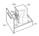
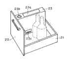
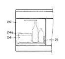
そのため、利用者の側において、適宜、図7や図8に示すような米びつ22,23を、開閉扉20の後側の引出し本体21内に収納したり、あるいは、図9に示すようなタッパと称される蓋24a付きの収納容器24内に米を入れ、これを引出し本体21内に収納したりしていた。
【0004】
図7に示した米びつ22は、一般載置形のものであり、前面上部に開閉式の米の投入口22aが設けられると共に、中程に計量操作用の複数の操作レバー22bが設けられ、下部に計量された米を取り出すトレイ22cが挿脱可能に設けられたものであり、米を取り出すには、必要な量に対応した操作レバー22bを押し下げ、米をトレイ2cに落下させた後、このトレイ22cを米びつ22から前方に引出し、取り出すようにしていた。
【0005】
また、図8に示した米びつ23は、上面に米の投入口23aと、計量用の操作釦23bが設けられた薄型のものであり、米は米びつ23の側面の下端寄りに設けられたトレイ23cを米びつ23の側方に引き出すことにより、行うようになっている。
【0006】
さらに、図9に示したタッパと称される収納容器24を米の収納に用いた場合、米を取り出すには、蓋24aを開けた後、収納された米を升などを用いて掬い取るようにしていた。
【0007】
【発明が解決しようとする課題】
上述した従来の厨房家具用キャビネットのうち、図7や図8に示すような米びつを収納したものは、米びつの前方あるいは側方に操作用の空間が必要なため、ここに物を置くことができず、引出し内の収納量が減少するという問題点があった。
【0008】
また、図9に示したタッパと称される収納容器を用いた場合は、米を取り出す際、一々、収納容器の蓋を開け、升などを用いてこの容器内に収納された米を掬い取らなくてはならず、煩わしく、作業も行い難いという問題点があった。また、このタッパの上側には物が置けないので、収納スペースの無駄が多く、キャビネット内の収納量が少なくなるという問題点もあった。
【0009】
さらにまた、上述したものは何れも米を取り出す際、まずキャビネットの開閉扉を開放しなくてはならず、開閉扉を閉めたまま、直接、米を取り出すことができず、この面からも操作性が悪いという問題点も有していた。
【0010】
本発明は、上記従来の厨房家具用キャビネットが有していた問題点の解決を課題とする。
【0011】
【課題を解決するための手段】
上記の課題を解決するために、本発明のうち、請求項1記載の発明は、略箱形で前面に引出し式の開閉扉を備えたコンロ台や流し台などの厨房家具用キャビネットにおいて、上記開閉扉の内側の引出し本体上に、米を収納保管する収納部と、この収納部の下方に連続し、規定量の米を計量落下させる計量機構部と、計量機構部から落下した米を受けるトレイとを具備した米びつを一体的に取り付けた。そして、この米びつを、上面に計量機構部の操作釦が設けられると共に、米びつの下端寄りに装填されるトレイを挿脱する引出し部が上下方向に出没可能に設けらたものとしたことを特徴とする。
【0012】
請求項2記載の発明は、略箱形で前面に引出し式の開閉扉を備えたコンロ台や流し台などの厨房家具用キャビネットにおいて、上記開閉扉の内側の引出し本体上に、米を収納保管する収納部と、この収納部の下方に連続し、規定量の米を計量落下させる計量機構部と、計量機構部から落下した米を受けるトレイとを具備した米びつを一体的に取り付け、開閉扉の前面に、前記計量機構部を操作する操作釦を設けると共に、前記トレイを挿脱可能な開口を設けたことを特徴とする。
【0013】
【発明の実施の形態】
以下、本発明を図示した実施の形態に基づき詳細に説明する。
【0014】
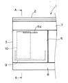
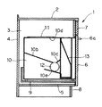
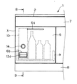
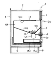
図1は、本発明に係る厨房家具用キャビネットの実施形態を示した要部簡略正面図、図2は、図1のA−A線の断面図である。
【0015】
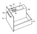
図示したように、このキャビネット1は、ワークトップと称せられる天板2と、左右両側の側板3、背面板4、および底板5とで前面(図2において右面)が開放された箱形に形成されたものであり、前面の開放部分には、引出し式に前方に引き出される開閉扉6が設けられている。この開閉扉6は、図4に示すように、上面が開放された引出し本体9の前面板を兼ねるものであり、その前面上部には、開閉操作用の把手6aが設けられている。
【0016】
なお、図において符号8は、キャビネット1の下端の蹴込みとなる台輪部、7は、開閉扉6の上側前面を塞いだ幕板を示す。
【0017】
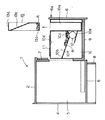
ここにおいて本発明の厨房家具用キャビネット1では、開閉扉6の裏面に一体に設けられた引出し本体9の片側に、薄型で奥行きが引出し本体9の奥行き寸法とほぼ等しい米びつ10を一体的に取り付けている。この米びつ10は、前側(図2や図3において右側)の上下方向に空洞部10aが設けられると共に、内部の中程に設けられた傾斜案内板10b,10cで上下に区分されたものであり、上面に設けられた投入口10dから投入された米Rは、この傾斜案内板10b,10cの上側にストックされるようになっている。また、傾斜案内板10b,10cの下側には、この傾斜案内板10b,10cを滑り落ちた米Rを計量し、その下側のシュート10eに排出する計量機構部12が設けられ、この計量機構部12は、米びつ10の上面に設けられた操作釦14で操作されるようになっている。また、米びつ10の前側に設けられた空洞部10aには、図3に示すように、シュート10eの下端が臨むと共に、下端にトレイ13cが設けられた縦長の引出し部13が、挿脱可能に装填されるようになっている。なお、この引出し部13は、角筒形で少なくともその一側が開放され、この開放された下側部分を容器状のトレイ13cとしたものであり、上端には手かがりとなるスリット状の開口13aが設けられている。また、その内部は、傾斜した仕切り部13bで上下に区分され、引出し部13が空洞部10aに装填された際、トレイ13cが外部に露呈しないようにしている。なお、この装填時、引出し部13の開放された側(図3において左側)が、計量機構部12が設けられた側に面し、トレイ13cはシュート10eの下端より下方に位置している。
【0018】
なお、図2〜4において、符号11は、米の投入口10dを塞いだ蓋を示す。
【0019】
本発明の厨房家具用キャビネット1は、上記の構成を有している。
【0020】
次に、このキャビネット1に一体的に組み込まれた米びつ10の使用法について述べると、まず、米Rを収納するには、開閉扉6をキャビネット1の前方(図3において右方)に引き出し、現れた米びつ本体10の上面に設けられた投入口10dの蓋11を開放し、この投入口10dから米Rを内部に投入すれば良く、このことで米Rは、図3に示すように傾斜案内板10b,10cの上側の収納部10fに入り、ここで収納保管される。そして、米Rの投入後は、投入口10dの蓋11を閉じ、開閉扉6を閉めれば良い。
【0021】
次に、この米びつ10に収納された米Rを取り出すには、まず開閉扉6を前方(図3において右方)に引き出し、現れた米びつ10の上面に設けられた操作釦14を押せば、傾斜案内板10b,10cを滑り落ちて計量機構部12に投入された一定容積の米Rが、この計量機構部12から落下排出され、この落下排出された米Rは、シユート10eを介して空洞部10a内に位置した引出し部13のトレイ13cで受けられるようになっている。なお、一回の操作釦14の操作で排出される米Rの量は、規定の最少単位量に設定されている。従って、多量の米粒を必要とする場合は、操作釦14を必要な回数だけ操作すれば良い。
【0022】
このようにして、必要量の米Rの排出が完了すると、次に図3に矢印で示すように、引出し部13を米びつ10の上側に引き開ければ良く、このことで規定量の米Rが外部に取り出されるものである。
【0023】
そして、トレイ13cから米Rを取り出した後、空になった引出し部13を空洞部10a内に挿入すれば、トレイ13cはシュート10eから排出された米Rを受けることができる待機位置にセットされるので、開閉扉6を閉めれば、作業が完了する。
【0024】
以上のように本発明の厨房家具用キャビネット1では、米びつ10の上面から必要な米Rの投入や取り出しが行えるので、その周囲に他の物を置いても作業の妨げにならない。よって、引出し本体9上に米びつ10を設置しても、その収納量の減少は、最小限に抑えられるものである。
【0025】
以上のようにして本発明の厨房家具用キャビネット1では、米Rの収納と取り出しが行えるものである。
【0026】
なお、上記の実施の形態では、引出し部13の下端にトレイ13cを一体的に設けたものを例示したが、トレイ13cは引出し部13と別体に形成され、引出し部13の下端に着脱可能に取り付けられるようになったものであっても良い。
【0027】
図5と図6は、本発明の他の実施形態を示した要部正面側と、その要部断面図である。図示したようにこの場合は、米びつ10が設けられた前側の開閉扉6に、計量機構部12を操作する操作釦14と、トレイ13dを計量機構部12の下側に挿入するための開口6bとを設けている。
【0028】
従って、上述した米びつ10に設けられていた空洞部10aに相当するものはなく、米びつ10の上半部分は全て米Rの収納部10fとされている。また、計量機構部12の下側のシュート10eに相当するものも設けられていない。そして、この場合、トレイ13dは上面が開放された細長い引出し状に形成されており、計量機構部12から落下した米Rは、その下側に設けられた開口13eからこのトレイ13d内に落下するようになっている。その他の構成は、上記実施形態のものと全く同じである。
【0029】
この実施形態のキャビネット1に収納された米Rを取り出すには、まず開閉扉6の前面に設けられた操作釦14を押し込み、このことで、傾斜案内板10b,10cを滑り落ちて計量機構部12に投入された一定容積の米Rを計量機構部12から下方のトレイ13dに落下させる。なお、この時、一回の操作で排出される米Rの量は一定なので、必要とする米Rの量が多い場合は、複数回、操作釦14を押すこととする。このことで、必要な量の米Rがトレイ13dに落下して溜まるので、今度は、このトレイ13dを開閉扉6の前面に設けられた開口6bから前方に引き出せば良い。
【0030】
このようにして米Rが取り出され、空になったトレイ13dを開口6bから挿入すれば、このトレイ13dは、計量機構部12から落下排出された米Rを受け取り可能な待機位置にセットされるものである。
【0031】
このように、この実施形態のキャビネット1では、開閉扉6を開閉しなくてもその前面から容易に必要な量の米Rを取り出すことができる。また、米びつ10の前部に引出し部13を挿脱するための空洞部13aを設ける必要がないので、米Rの収納部10fの容積を大きくでき、同じ外寸の場合、その収納容量を大きくすることができる。なお、この米びつ10への米Rの収納や補充は、前記実施形態のものと同様に、開閉扉6を開けた後、米びつ10の上面に設けられた投入口10dから行うものである。
【0032】
【発明の効果】
以上説明したように、本発明のうち、請求項1記載の発明では、キャビネットの引出し内に設置される米びつの上面に、計量機構部の操作釦とトレイの引出し部を設けたので、米の取り出し操作が全て米びつの上面から行える。よって、米びつの周囲に操作用の空間を要さず、収納スペースを最大限利用して米を体裁良く、キャビネット内に収納できるという効果がある。
【0033】
また、請求項2記載の発明は、キャビネット前面の開閉扉に、内装された米びつの計量機構部の操作釦と、この米びつのトレイを挿脱可能な開口を設けたので、米の取り出し操作が開閉扉を開放することなく、全てキャビネットの外側から行える。よって、上記請求項1記載の発明の効果に加え、一層の操作性の向上がはかられることとなる。また、トレイを上方引出しするもののように、米びつの前側に空洞部を設ける必要がないので、米びつの内部に無駄なスペースがなくなり、米の収納容量が大きくなるという効果もある。
【図面の簡単な説明】
【図1】本発明に係る厨房家具用キャビネットの実施形態の要部正面図である。
【図2】図1のA−A線の断面図である。
【図3】図1に示したキャビネットの使用状態説明図である。
【図4】引出し部分の斜視図である。
【図5】他の実施形態の要部正面図である。
【図6】図5のB−B線の断面図である。
【図7】従来例による使用状態説明図である。
【図8】他の従来例による使用状態説明図である。
【図9】さらに他の従来例を示した要部正面図である。
【符号の説明】
1 キャビネット
2 天板
3 側板
4 背板
5 底板
6 開閉扉
6b 開口
9 引出し本体
10 米びつ
10a 空洞部
10f 米の収納部
12 計量機構部
13 引出し部
13c,13d トレイ
14 操作釦[0001]
TECHNICAL FIELD OF THE INVENTION
The present invention relates to a cabinet for kitchen furniture such as a stove or a sink having a function of storing rice.
[0002]
[Prior art]
Heretofore, there has been no kitchen furniture cabinet in which a rice bin is integrated into such a drawer-type opening / closing door.
[0003]
Therefore, on the user's side, the rice bins 22 and 23 as shown in FIGS. 7 and 8 are appropriately stored in the drawer body 21 on the rear side of the opening / closing door 20, or a tapper as shown in FIG. The rice was put in a storage container 24 with a lid 24a, which is referred to as a container, and this was stored in the drawer body 21.
[0004]
The rice bin 22 shown in FIG. 7 is of a general placing type. The rice bin 22 is provided with an opening / closing rice input port 22a at an upper front portion, a plurality of operation levers 22b for weighing operation at a middle position, and a lower portion. The tray 22c for taking out the weighed rice is provided so as to be insertable and removable. To take out the rice, the operation lever 22b corresponding to the required amount is pushed down, and the rice is dropped onto the tray 2c. The tray 22c was pulled out from the rice bin 22 and taken out.
[0005]
The rice bottle 23 shown in FIG. 8 is a thin type provided with a rice inlet 23a and an operation button 23b for weighing on the upper surface, and rice is provided in a tray provided near the lower end of the side surface of the rice bin 23. By pulling out 23c to the side of rice bin 23, it is performed.
[0006]
Further, when the storage container 24 called a tapper shown in FIG. 9 is used for storing rice, in order to take out the rice, open the lid 24a, and then scoop the stored rice using a box or the like. I was
[0007]
[Problems to be solved by the invention]
Among the above-mentioned conventional cabinets for kitchen furniture, those that store rice bins as shown in FIGS. 7 and 8 require a space for operation in front of or side of the rice bins, so that objects can be placed here. However, there is a problem that the storage amount in the drawer is reduced.
[0008]
When a storage container called a tapper shown in FIG. 9 is used, when taking out the rice, the lid of the storage container is opened, and the rice stored in the container is scooped using a box or the like. It is indispensable, cumbersome, and difficult to perform. Further, since no objects can be placed on the upper side of the tapper, there is a problem that storage space is wasted much and the amount of storage in the cabinet is reduced.
[0009]
Furthermore, in any of the above, when taking out rice, the door of the cabinet must first be opened, and rice cannot be directly taken out with the door closed, and the operation can be performed from this side as well. There was also a problem of poor performance.
[0010]
An object of the present invention is to solve the problems of the conventional kitchen furniture cabinet.
[0011]
[Means for Solving the Problems]
In order to solve the above-mentioned problems, the invention according to claim 1 of the present invention relates to a kitchen furniture cabinet such as a stove stand or a sink provided with a drawer-type opening / closing door on the front in a substantially box shape. A storage unit for storing and storing rice on the drawer body inside the door, a weighing mechanism that continues below this storage unit and weighs out a specified amount of rice, and a tray that receives rice dropped from the weighing mechanism And a rice bin equipped with The rice bin is provided with an operation button of a weighing mechanism on an upper surface, and a drawer for inserting and removing a tray loaded near the lower end of the rice bin is provided so as to be able to protrude and retract in a vertical direction. And
[0012]
According to a second aspect of the present invention, in a cabinet for kitchen furniture such as a stove or a sink provided with a drawer-type opening / closing door on the front surface in a substantially box shape, rice is stored and stored on a drawer body inside the opening / closing door. A storage bin, a rice bin having a weighing mechanism that is continuous below the storage and weighs a prescribed amount of rice and a tray that receives the rice dropped from the weighing mechanism is integrally attached to the opening and closing door. An operation button for operating the weighing mechanism is provided on the front surface, and an opening through which the tray can be inserted and removed is provided.
[0013]
BEST MODE FOR CARRYING OUT THE INVENTION
Hereinafter, the present invention will be described in detail based on illustrated embodiments.
[0014]
FIG. 1 is a simplified front view of an essential part showing an embodiment of a cabinet for kitchen furniture according to the present invention, and FIG. 2 is a sectional view taken along line AA of FIG.
[0015]
As shown in the drawing, the cabinet 1 is formed in a box shape having an open front surface (right surface in FIG. 2) of a top plate 2 called a worktop, and side plates 3, a back plate 4 and a bottom plate 5 on both left and right sides. An opening / closing door 6 is provided at an open portion on the front surface, which is pulled out and pulled forward. As shown in FIG. 4, the opening / closing door 6 also serves as a front plate of the drawer main body 9 whose upper surface is open, and a handle 6a for opening / closing operation is provided on the upper front surface.
[0016]
In the drawing, reference numeral 8 denotes a base ring portion which is to be inserted into the lower end of the cabinet 1, and reference numeral 7 denotes a curtain plate which covers the upper front surface of the opening / closing door 6.
[0017]
Here, in the kitchen furniture cabinet 1 of the present invention, a rice bin 10 which is thin and has a depth substantially equal to the depth dimension of the drawer main body 9 is integrally attached to one side of the drawer main body 9 integrally provided on the back surface of the opening / closing door 6. ing. The rice bin 10 is provided with a cavity 10a in the vertical direction on the front side (right side in FIGS. 2 and 3), and is vertically divided by inclined guide plates 10b and 10c provided in the middle of the inside. The rice R supplied from the input port 10d provided on the upper surface is stocked above the inclined guide plates 10b and 10c. Below the inclined guide plates 10b and 10c, there is provided a measuring mechanism section 12 for measuring the rice R sliding down the inclined guide plates 10b and 10c and discharging the rice R to a chute 10e below the rice R. The mechanism 12 is operated by an operation button 14 provided on the upper surface of the rice bin 10. As shown in FIG. 3, the lower end of the chute 10e faces the hollow portion 10a provided on the front side of the rice bin 10, and the vertically extending drawer 13 provided with the tray 13c at the lower end can be inserted and removed. It is to be loaded. The drawer 13 has a rectangular cylindrical shape, at least one side of which is open, and the open lower portion is a container-like tray 13c. Is provided. Further, the inside thereof is vertically divided by an inclined partition portion 13b so that the tray 13c is not exposed to the outside when the drawer portion 13 is loaded in the hollow portion 10a. At the time of loading, the open side (left side in FIG. 3) of the drawer unit 13 faces the side where the weighing mechanism unit 12 is provided, and the tray 13c is located below the lower end of the chute 10e.
[0018]
In addition, in FIGS. 2-4, the code | symbol 11 shows the lid which closed 10 d of rice inlets.
[0019]
The kitchen furniture cabinet 1 of the present invention has the above-described configuration.
[0020]
Next, the usage of the rice bin 10 integrated into the cabinet 1 will be described. First, in order to store the rice R, the door 6 is pulled out to the front of the cabinet 1 (to the right in FIG. 3). The lid 11 of the inlet 10d provided on the upper surface of the emerged rice bin main body 10 may be opened, and the rice R may be inserted into the inside through the inlet 10d, whereby the rice R is inclined as shown in FIG. It enters the storage section 10f above the guide plates 10b and 10c, where it is stored and stored. Then, after the rice R has been charged, the lid 11 of the slot 10d may be closed, and the door 6 may be closed.
[0021]
Next, in order to take out the rice R stored in the rice bin 10, first, pull out the opening / closing door 6 forward (to the right in FIG. 3) and press the operation button 14 provided on the upper surface of the rice bin 10 that appears. A certain volume of rice R that has been slid down the inclined guide plates 10b and 10c and entered into the weighing mechanism 12 is dropped and discharged from the weighing mechanism 12, and the dropped and discharged rice R is hollowed out through the shot 10e. The tray 13c of the drawer 13 located in the section 10a can receive the sheet. The amount of rice R discharged by one operation of the operation button 14 is set to a prescribed minimum unit amount. Therefore, when a large amount of rice grains are required, the operation button 14 may be operated a required number of times.
[0022]
When the necessary amount of rice R has been discharged in this way, the drawer 13 may be pulled out above the rice bin 10 as shown by an arrow in FIG. It is taken out.
[0023]
Then, after taking out the rice R from the tray 13c, if the empty drawer 13 is inserted into the hollow portion 10a, the tray 13c is set to the standby position where the rice R discharged from the chute 10e can be received. Therefore, when the door 6 is closed, the operation is completed.
[0024]
As described above, in the cabinet 1 for kitchen furniture of the present invention, necessary rice R can be put in and taken out from the upper surface of the rice bin 10, so that placing other objects around the rice bottle 10 does not hinder the work. Therefore, even if the rice bin 10 is set on the drawer main body 9, the reduction in the storage amount can be minimized.
[0025]
As described above, the cabinet 1 for kitchen furniture of the present invention can store and take out the rice R.
[0026]
In the above-described embodiment, the tray 13c is integrally provided at the lower end of the drawer 13. However, the tray 13c is formed separately from the drawer 13, and is detachably attached to the lower end of the drawer 13. It may be one that can be attached to.
[0027]
5 and 6 are a front view of a main part and a cross-sectional view of the main part showing another embodiment of the present invention. As shown in the figure, in this case, an operation button 14 for operating the weighing mechanism unit 12 and an opening 6b for inserting the tray 13d below the weighing mechanism unit 12 are provided on the front opening / closing door 6 provided with the rice bin 10. Are provided.
[0028]
Therefore, there is no equivalent to the cavity 10a provided in the rice bin 10 described above, and the upper half portion of the rice bin 10 is entirely a storage section 10f for rice R. Further, a component corresponding to the lower chute 10e of the weighing mechanism 12 is not provided. In this case, the tray 13d is formed in an elongated drawer shape having an open upper surface, and the rice R dropped from the weighing mechanism 12 falls into the tray 13d from an opening 13e provided on the lower side. It has become. Other configurations are exactly the same as those of the above embodiment.
[0029]
In order to take out the rice R stored in the cabinet 1 of this embodiment, first, the operation button 14 provided on the front surface of the opening / closing door 6 is pushed in, whereby the inclined guide plates 10b and 10c are slid down and the weighing mechanism section. A certain volume of rice R put into the tray 12 is dropped from the weighing mechanism 12 to a tray 13d below. At this time, since the amount of rice R discharged by one operation is constant, if the required amount of rice R is large, the operation button 14 is pressed a plurality of times. As a result, a necessary amount of rice R falls and accumulates on the tray 13d, and this time, the tray 13d may be pulled forward from the opening 6b provided on the front surface of the opening / closing door 6.
[0030]
When the rice R is taken out in this way and the empty tray 13d is inserted through the opening 6b, the tray 13d is set at a standby position where the rice R dropped and discharged from the weighing mechanism unit 12 can be received. Things.
[0031]
Thus, in the cabinet 1 of this embodiment, a required amount of rice R can be easily taken out from the front surface of the cabinet 1 without opening and closing the door 6. Further, since there is no need to provide a cavity 13a for inserting and removing the drawer 13 at the front of the rice bin 10, the volume of the storage portion 10f of the rice R can be increased, and in the case of the same outer dimensions, the storage capacity is increased. can do. The storage and replenishment of the rice R into the rice bin 10 are performed through the opening 10d provided on the upper surface of the rice bin 10 after the opening and closing door 6 is opened, similarly to the above embodiment.
[0032]
【The invention's effect】
As described above, in the invention according to claim 1 of the present invention, the operation button of the weighing mechanism and the drawer of the tray are provided on the upper surface of the rice bin installed in the drawer of the cabinet. All removal operations can be performed from the top of the rice bin. Therefore, there is an effect that rice can be stored in the cabinet in a good manner by utilizing the storage space to the maximum without requiring an operation space around the rice bin.
[0033]
According to the second aspect of the present invention, the operation button of the built-in rice bin measuring mechanism and the opening through which the rice bin tray can be inserted / removed are provided on the opening / closing door on the front of the cabinet. All can be done from outside the cabinet without opening the door. Therefore, in addition to the effects of the first aspect of the present invention, the operability is further improved. Further, unlike the case where the tray is pulled out upward, there is no need to provide a cavity in the front side of the rice bin, so that there is no wasteful space inside the rice bin and there is also an effect that the storage capacity of rice is increased.
[Brief description of the drawings]
FIG. 1 is a front view of a main part of a kitchen furniture cabinet according to an embodiment of the present invention.
FIG. 2 is a sectional view taken along line AA of FIG.
FIG. 3 is an explanatory diagram of a use state of the cabinet shown in FIG. 1;
FIG. 4 is a perspective view of a drawer portion.
FIG. 5 is a front view of a main part of another embodiment.
FIG. 6 is a sectional view taken along line BB of FIG. 5;
FIG. 7 is an explanatory diagram of a use state according to a conventional example.
FIG. 8 is an explanatory diagram of a use state according to another conventional example.
FIG. 9 is a front view of a main part showing still another conventional example.
[Explanation of symbols]
DESCRIPTION OF SYMBOLS 1 Cabinet 2 Top plate 3 Side plate 4 Back plate 5 Bottom plate 6 Opening / closing door 6b Opening 9 Drawer main body 10 Rice bin 10a Cavity part 10f Rice storage part 12 Weighing mechanism part 13 Drawer parts 13c, 13d Tray 14 Operation buttons