JP2004217455A - Chlorine gas drying equipment - Google Patents
Chlorine gas drying equipment Download PDFInfo
- Publication number
- JP2004217455A JP2004217455A JP2003005393A JP2003005393A JP2004217455A JP 2004217455 A JP2004217455 A JP 2004217455A JP 2003005393 A JP2003005393 A JP 2003005393A JP 2003005393 A JP2003005393 A JP 2003005393A JP 2004217455 A JP2004217455 A JP 2004217455A
- Authority
- JP
- Japan
- Prior art keywords
- sulfuric acid
- chlorine gas
- drying
- supply port
- gas
- Prior art date
- Legal status (The legal status is an assumption and is not a legal conclusion. Google has not performed a legal analysis and makes no representation as to the accuracy of the status listed.)
- Pending
Links
Images
Landscapes
- Drying Of Gases (AREA)
Abstract
Description
【0001】
本発明は、塩素ガスの乾燥装置に関し、詳しくは水分を含む塩素ガスを硫酸と接触させて乾燥させるための乾燥装置に関する。
【0002】
【従来の技術】
水分を含む塩素ガス(2)を乾燥させるための乾燥装置として、図1に示すような乾燥装置(1)が知られている(特許文献1:実開平6−24730号公報)。かかる乾燥装置(1)では、乾燥塔本体(10)内に、塔底(11)から水分を含む塩素ガス(2)を供給すると共に塔頂(12)から硫酸(3)を供給して、乾燥塔本体(10)内で塩素ガス(2)と液状の硫酸(3)とを接触させる。乾燥塔本体(10)内には、塩素ガス(2)が硫酸(3)と十分に接触するように、充填物(6)、泡鐘トレイ(7)などの気液接触部が設けられている。乾燥塔本体(10)内に供給された塩素ガス(2)は硫酸(3)に水分を吸収されて乾燥される。乾燥後の塩素ガス(2’)は塔頂(12)から外部に導かれる。
【0003】
かかる乾燥装置(1)には、機械的強度を確保するために、乾燥塔本体(10)や、気液接触部(6、7)などに炭素鋼、ステンレス鋼などの金属材料が用いられている。かかる金属材料は、塩素ガス(2)および硫酸(3)と直接接触しても腐食することがないように、例えばフッ素樹脂、塩化ビニル樹脂などの樹脂材料、無機ガラス、セラミクスなどの非金属無機材料などような、塩素および硫酸に対して不活性な非金属材料などで表面を被覆されて用いられていた。
【0004】
しかし、金属材料を非金属材料などで被覆することなく、そのまま用いても、長期間に亙り腐食を生ずることなく使用できれば、非金属材料などの被覆に要する費用を節約できて経済的にも有利である。また、非金属材料などで被覆したのでは、非金属材料などの被膜が破れないよう、洗浄塔本体の内部の点検、補修の際には慎重な取り扱いが必要となるが、機械的強度に優れた金属材料をそのまま使用することができれば、取り扱いが容易となる。
【0005】
【特許文献1】実開平6−24730号公報
【0006】
【発明が解決しようとする課題】
そこで本発明者は、金属材料を非金属材料などで被覆することなくそのまま用いても、長期間に亙り、この金属材料を腐食させることなく、硫酸による塩素ガスの乾燥に使用できる乾燥装置を開発するべく鋭意検討した結果、質量分率でクロムを18%〜24%、モリブデンを12%〜18%、鉄を0.5%〜7%それぞれ含有するニッケル基合金材は、十分な機械的強度を有していて慎重な取扱いを必要とせず、また、硫酸の存在下では塩素によって腐食し難いことを見出し、本発明に至った。
【0007】
【課題を解決するための手段】
すなわち本発明は、水分を含む塩素ガス(2)を硫酸(3)と接触させて乾燥させるための乾燥装置(1)であり、
塩素ガス(2)および硫酸(3)と接触する金属材料を有し、
前記金属材料は質量分率でクロムを18%〜24%、モリブデンを12%〜18%および鉄を0.5%〜7%それぞれ含有するニッケル基合金材である
ことを特徴とする前記塩素ガス(2)の乾燥装置(1)を提供するものである。
【0008】
【発明の実施の形態】
以下、図1に基づき、本発明の乾燥装置(1)について説明する。図1に示す乾燥装置(1)は、乾燥塔本体(10)を備えている。この乾燥塔本体(10)の塔底(11)からは、塩素ガス供給配管(L1)を通じて塩素ガス(2)が供給される。この塩素ガス(2)には水分が含まれているが、その含有量はモル分率で通常0.5%以上3%以下程度である。かかる塩素ガス(2)は、二酸化炭素、窒素、アルゴン、酸素などの不純物成分を含んでいてもよい。塩素ガス(2)の温度は通常0℃以上50℃以下程度である。
【0009】
一方、塔頂(12)からは硫酸(3)が供給される。硫酸(3)は、塔頂(12)に設けられた硫酸供給口(5)から流下または滴下して供給してもよいし、例えば供給口(5)を噴霧ノズルとし、硫酸を噴霧して液滴として供給してもよい。硫酸供給口(5)から供給される硫酸(3)としては、塩素ガス(2)を十分に乾燥させることができる点で、通常は濃度が質量分率で90%〜98%程度のいわゆる濃硫酸が用いられる。供給される硫酸(3)は液状であり、その温度は通常0℃以上40℃以下程度である。
【0010】
乾燥塔本体(10)内には気液接触部として、下部に充填物(6)が充填され、上部に泡鐘トレイ(7)が設けられている。塩素ガス(2)はこれら充填物(6)および泡鐘トレイ(7)などの気液接触部を通過して、塔頂(12)まで上昇する。硫酸(3)は、塔頂に設けられた硫酸供給口(5)から供給され、泡鐘トレイ(7)および充填物(6)を通過して、塔底(11)に流下する。塩素ガス(2)と硫酸(3)とがこれら充填物(6)および泡鐘トレイ(7)などの気液接触部において互いに気液接触することで、塩素ガス(2)は水分が硫酸(3)に吸収されて乾燥される。乾燥後の塩素ガス(2’)は配管(L3)を通じて外部に導かれる。
【0011】
かかる乾燥塔本体(10)において、硫酸供給口(5)から供給された硫酸(31)は、塩素ガス(2)と接触して水分を吸収しながら塔底(11)に到達し、ここに貯留される。塔底に貯留される硫酸(32)は吸収した水分によって希釈されており、その濃度は質量分率で通常60%以上95%以下程度であり、通常は濃度がこの範囲となるように、塔本体(10)内に供給される硫酸(3)の濃度、使用量が決められる。
【0012】
塔底(11)に貯留される硫酸(32)は水分を含んでいるが、通常は水分を更に吸収しうるので、これをポンプ(P)により回収し、必要により熱交換器(C)で温度調節したのち、回収硫酸供給口(8)から乾燥塔本体(10)内に供給してもよい。回収された硫酸は、回収硫酸供給口(8)から流下して、または滴下して塔本体(10)内に供給される。また、供給口(8)を噴霧ノズルなどとし、回収された硫酸を噴霧して液滴として供給してもよい。回収され、再び本体(10)内に供給された硫酸(33)は、更に水を吸収する。回収硫酸供給口(8)は通常、硫酸供給口(5)よりも下方に設けられ、図1に示す乾燥装置では泡鐘トレイ(7)の下方に設置されている。塔底から回収された硫酸の一部(34)は系外に排出される。
【0013】
本発明の乾燥装置(1)は、塩素ガスおよび硫酸と接触する金属材料を有している。図1に示す乾燥装置(1)において、乾燥塔本体(10)の内面や、乾燥塔本体(10)内部の硫酸供給口(5)、充填物(6)、泡鐘トレイ(7)および回収硫酸供給口(8)は、塩素ガス(2)および硫酸(3)と接触する。乾燥後の塩素ガス(2’)には硫酸の飛沫が含まれるので、かかる乾燥後の塩素ガス(2)を外部に導く配管(L3)も、塩素ガスおよび硫酸と接触する。塔底の硫酸(32)を塔底(11)からポンプ(P)に導く配管(L4)、ポンプ(P)から熱交換器(C)に導く配管(L5)、熱交換器(C)から回収硫酸供給口(8)に導く配管(L6)、系外に排出する配管(L7)は、内部を通過する硫酸(34)に塩素ガス(2)が混入することもあることから、塩素ガスおよび硫酸と接触することがある。本発明の乾燥装置(1)において、これら乾燥塔本体(10)の内面や、本体内部の充填物(6)、泡鐘トレイ(7)などの気液接触部、硫酸供給口(5)、回収硫酸供給口(8)、各配管(L3〜L7)および熱交換器(C)などの各部材は、全部または一部が金属材料で構成されている。
【0014】
本発明の乾燥装置(1)は、かかる金属材料のうちに、非金属材料で被覆されることなくそのまま用いられていて、塩素ガスおよび硫酸と接触する金属材料を有している。かかる金属材料は、質量分率でクロムを18%〜24%、モリブデンを12%〜18%、および鉄を0.5%〜7%含有するニッケル基合金材である。ここで、ニッケル基合金材とは、ニッケルを主成分とし、他の金属成分を含む合金である。クロム含有量が18%未満であると、腐食が生じ易い傾向にある。かかるニッケル基合金材はタングステンの含有量が0で実質的に含有しなくてもよいし、含有していてもよい。タングステンを含有する場合、その含有量は通常5%以下である。かかるニッケル基合金材は0.2%程度以下であればシリコンを、また0.02%程度以下であれば炭素をそれぞれ含有していてもよい。
【0015】
かかるニッケル基合金材としては、市販されているものを用いることができ、例えば三菱マテリアル(株)から「Alloy 22」、Krupp VDM社(ドイツ)から「Alloy 59」などとして、各種形状、例えば板状、棒状、管状のものが市販されているので、これらをそのままで、または加工して用いればよい。
【0016】
【発明の効果】
本発明の乾燥装置は、塩素ガスおよび硫酸と接触する金属材料が上記ニッケル基合金材であるので、その表面を樹脂材料、非金属無機材料などの非金属材料などで被覆しなくても、塩素ガスおよび硫酸によって腐食することがない。このため、本発明の乾燥装置は、金属材料を非金属材料などで被覆することなく、経済的に有利に製作することができる。また、上記ニッケル基合金材は機械的強度も十分であるので、点検、補修に際して慎重な取り扱いをする必要もない。
【0017】
【実施例】
以下、実施例によって本発明をより詳細に説明するが、本発明は、かかる実施例によって限定されるものではない。
【0018】
参考例1
第1表に記載の組成の合金材A、合金材Bおよび合金材Cをそれぞれ板状(75mm×15mm×2mm)に切出して試験片とし、U字型に曲げてUベント試験片とした。この試験片を濃度が質量分率で65%、80%、90%の硫酸水溶液にそれぞれ浸漬した。同時に、同様に切出しU字型に曲げたUベント試験片を各硫酸水溶液の上方の気相中にそれぞれ配置した。40℃を維持しながら168時間の間、硫酸水溶液に塩素ガス(純度約100%)をバブリングして吹き込んだ。塩素ガスを吹き込むことで、気相中に配置した試験片の表面には硫酸飛沫が付着していた。その後、試験片を取出し、水洗し、乾燥して、表面を目視で観察した。また試験片の質量の減少量を測定して、腐食速度を求めた。結果を第2表に示す。
【0019】
【表1】

【表2】
実施例1
図1に示す乾燥装置(1)において、乾燥塔本体(10)、硫酸供給口(5)、充填物(6)、泡鐘トレイ(7)、回収硫酸供給口(8)、乾燥後の塩素ガスを外部に導く配管(L3)、塔底の硫酸をポンプに導く配管(L4)、この硫酸をポンプから熱交換器に導く配管(L5)、熱交換器(C)、硫酸を熱交換器から回収硫酸供給口に導く配管(L6)、硫酸を熱交換器から系外に排出する配管(L7)を表1に記載の合金材Aまたは合金材Bで構成した塩素ガスの乾燥装置(1)は、乾燥塔本体(10)、硫酸供給口(5)、充填物(6)、泡鐘トレイ(7)、回収硫酸供給口(8)、熱交換器(C)、各配管(L3、L4、L5、L6、L7)の表面を樹脂材料、非金属無機材料などの非金属材料で被覆しなくても、長期間に亙り腐食を生ずることなく、水分を含む塩素ガス(2)を塩素ガス供給配管(L1)から供給して乾燥させることができる。
【図面の簡単な説明】
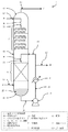
【図1】塩素ガスの乾燥装置の一例を模式的に示す断面図である。
【符号の説明】
1:塩素ガスの乾燥装置
10:乾燥塔本体 11:塔底 12:塔頂
2:水分を含む塩素ガス 2’:乾燥後の塩素ガス
3、31、32、33、34:硫酸
5:硫酸供給口 6:充填物 7:泡鐘トレイ
8:回収硫酸供給口
P:ポンプ C:熱交換器 L1〜L7:配管[0001]
The present invention relates to a drying apparatus for chlorine gas, and more particularly, to a drying apparatus for drying chlorine gas containing water by bringing the chlorine gas into contact with sulfuric acid.
[0002]
[Prior art]
As a drying apparatus for drying chlorine gas (2) containing water, a drying apparatus (1) as shown in FIG. 1 is known (Japanese Patent Application Laid-Open No. Hei 6-24730). In the drying apparatus (1), a chlorine gas (2) containing water is supplied from the bottom (11) into the drying tower body (10), and sulfuric acid (3) is supplied from the top (12). The chlorine gas (2) is brought into contact with the liquid sulfuric acid (3) in the drying tower main body (10). A gas-liquid contact portion such as a packing (6) and a bubble bell tray (7) is provided in the drying tower main body (10) so that the chlorine gas (2) sufficiently contacts the sulfuric acid (3). I have. The chlorine gas (2) supplied into the drying tower main body (10) is absorbed by the sulfuric acid (3) to be dried. The dried chlorine gas (2 ') is led outside from the top (12).
[0003]
In the drying apparatus (1), a metal material such as carbon steel or stainless steel is used for the drying tower body (10) and the gas-liquid contact portions (6, 7) in order to secure mechanical strength. I have. Such metal materials are not corroded even when they come into direct contact with chlorine gas (2) and sulfuric acid (3), for example, resin materials such as fluororesins and vinyl chloride resins, non-metallic inorganic materials such as inorganic glass and ceramics. It has been used with its surface coated with a nonmetallic material inert to chlorine and sulfuric acid, such as a material.
[0004]
However, if the metal material can be used without being coated with a non-metallic material or the like and used without corrosion for a long period of time, the cost required for coating the non-metallic material or the like can be saved, and it is economically advantageous. It is. When coated with a non-metallic material, etc., careful handling is required when inspecting and repairing the inside of the main body of the washing tower so that the coating of the non-metallic material etc. will not be broken, but it has excellent mechanical strength If the used metal material can be used as it is, handling becomes easy.
[0005]
[Patent Document 1] Japanese Utility Model Laid-Open No. 6-24730
[Problems to be solved by the invention]
Therefore, the present inventor has developed a drying apparatus which can be used for drying chlorine gas with sulfuric acid without corroding the metal material for a long period of time even if the metal material is used without being coated with a non-metal material or the like. As a result of intensive studies, a nickel-based alloy material containing 18% to 24% of chromium, 12% to 18% of molybdenum, and 0.5% to 7% of iron by mass fraction has sufficient mechanical strength. It has been found that they do not require careful handling and that they are hardly corroded by chlorine in the presence of sulfuric acid, leading to the present invention.
[0007]
[Means for Solving the Problems]
That is, the present invention is a drying device (1) for drying by contacting chlorine gas (2) containing water with sulfuric acid (3),
A metal material that comes into contact with chlorine gas (2) and sulfuric acid (3);
The chlorine gas is characterized in that the metal material is a nickel-based alloy material containing 18% to 24% of chromium, 12% to 18% of molybdenum, and 0.5% to 7% of iron by mass fraction. (2) A drying device (1) is provided.
[0008]
BEST MODE FOR CARRYING OUT THE INVENTION
Hereinafter, the drying device (1) of the present invention will be described with reference to FIG. The drying device (1) shown in FIG. 1 includes a drying tower main body (10). A chlorine gas (2) is supplied from a bottom (11) of the drying tower body (10) through a chlorine gas supply pipe (L1). The chlorine gas (2) contains water, and its content is usually about 0.5% to 3% by mole fraction. Such chlorine gas (2) may contain impurity components such as carbon dioxide, nitrogen, argon, and oxygen. The temperature of the chlorine gas (2) is usually about 0 ° C or more and 50 ° C or less.
[0009]
On the other hand, sulfuric acid (3) is supplied from the top (12). The sulfuric acid (3) may be supplied by dropping or dropping from a sulfuric acid supply port (5) provided at the top (12), or by, for example, using the supply port (5) as a spray nozzle and spraying sulfuric acid. It may be supplied as droplets. The sulfuric acid (3) supplied from the sulfuric acid supply port (5) usually has a concentration of about 90% to 98% in terms of mass fraction, so that the chlorine gas (2) can be sufficiently dried. Sulfuric acid is used. The supplied sulfuric acid (3) is in a liquid state, and its temperature is usually about 0 ° C or more and about 40 ° C or less.
[0010]
In the drying tower main body (10), a packing (6) is filled at a lower part as a gas-liquid contact part, and a bubble bell tray (7) is provided at an upper part. The chlorine gas (2) passes through gas-liquid contacts such as the packing (6) and the bubble cap tray (7) and rises to the top (12). The sulfuric acid (3) is supplied from a sulfuric acid supply port (5) provided at the top of the column, passes through the bubble bubble tray (7) and the packing (6), and flows down to the bottom (11). When the chlorine gas (2) and the sulfuric acid (3) come into gas-liquid contact with each other at a gas-liquid contact portion such as the packing (6) and the bubble-cap tray (7), the chlorine gas (2) loses the sulfuric acid ( Absorbed in 3) and dried. The dried chlorine gas (2 ′) is led to the outside through the pipe (L3).
[0011]
In the drying tower main body (10), the sulfuric acid (31) supplied from the sulfuric acid supply port (5) reaches the bottom (11) while contacting with the chlorine gas (2) and absorbing moisture, and reaches the bottom (11). Will be stored. The sulfuric acid (32) stored at the bottom of the column is diluted by the absorbed water, and its concentration is usually about 60% to 95% by mass fraction. The concentration and amount of sulfuric acid (3) supplied into the main body (10) are determined.
[0012]
The sulfuric acid (32) stored in the tower bottom (11) contains water, but usually it can further absorb water, so this is recovered by a pump (P) and, if necessary, by a heat exchanger (C). After adjusting the temperature, the recovered sulfuric acid may be supplied from the supply port (8) into the drying tower body (10). The recovered sulfuric acid is supplied to the tower body (10) by flowing down or dropping from the recovered sulfuric acid supply port (8). Alternatively, the supply port (8) may be a spray nozzle or the like, and the recovered sulfuric acid may be sprayed and supplied as droplets. The sulfuric acid (33) collected and supplied again into the main body (10) further absorbs water. The recovered sulfuric acid supply port (8) is usually provided below the sulfuric acid supply port (5), and is installed below the bubble cap tray (7) in the drying apparatus shown in FIG. A part (34) of the sulfuric acid recovered from the bottom of the column is discharged out of the system.
[0013]
The drying device (1) of the present invention has a metal material that comes into contact with chlorine gas and sulfuric acid. In the drying apparatus (1) shown in FIG. 1, the inner surface of the drying tower main body (10), the sulfuric acid supply port (5) inside the drying tower main body (10), the packing (6), the bubble cap tray (7) and the recovery The sulfuric acid supply port (8) contacts the chlorine gas (2) and the sulfuric acid (3). Since the dried chlorine gas (2 ′) contains splashes of sulfuric acid, the pipe (L3) for guiding the dried chlorine gas (2) to the outside also comes into contact with the chlorine gas and sulfuric acid. A pipe (L4) for guiding the sulfuric acid (32) at the bottom from the bottom (11) to the pump (P), a pipe (L5) for leading the heat from the pump (P) to the heat exchanger (C), and a pipe from the heat exchanger (C) The piping (L6) leading to the recovered sulfuric acid supply port (8) and the piping (L7) discharging to the outside of the system have chlorine gas (2) mixed with sulfuric acid (34) passing through the piping. And may come in contact with sulfuric acid. In the drying apparatus (1) of the present invention, the inner surface of the drying tower main body (10), a gas-liquid contact portion such as a packing (6) inside the main body, a bubble bell tray (7), a sulfuric acid supply port (5), Each member such as the recovered sulfuric acid supply port (8), each pipe (L3 to L7), and the heat exchanger (C) is entirely or partially made of a metal material.
[0014]
The drying device (1) of the present invention has a metal material that is used as it is without being coated with a nonmetallic material and that comes into contact with chlorine gas and sulfuric acid. Such a metal material is a nickel-based alloy material containing 18% to 24% of chromium, 12% to 18% of molybdenum, and 0.5% to 7% of iron by mass fraction. Here, the nickel-based alloy material is an alloy containing nickel as a main component and other metal components. If the chromium content is less than 18%, corrosion tends to occur. Such a nickel-based alloy material has a tungsten content of 0 and may or may not substantially contain tungsten. When tungsten is contained, its content is usually 5% or less. Such a nickel-based alloy material may contain silicon if it is about 0.2% or less, and may contain carbon if it is about 0.02% or less.
[0015]
As the nickel-based alloy material, commercially available ones can be used. For example, various shapes such as “Alloy 22” from Mitsubishi Materials Corporation and “Alloy 59” from Krupp VDM (Germany) are used. Shapes, rods, and tubes are commercially available. These may be used as they are or after being processed.
[0016]
【The invention's effect】
In the drying apparatus of the present invention, since the metal material that comes into contact with chlorine gas and sulfuric acid is the above-mentioned nickel-based alloy material, even if the surface thereof is not coated with a non-metal material such as a non-metallic inorganic material, the chlorine No corrosion by gas and sulfuric acid. Therefore, the drying apparatus of the present invention can be manufactured economically and advantageously without coating a metal material with a nonmetallic material or the like. Further, since the nickel-based alloy material has a sufficient mechanical strength, it is not necessary to handle the nickel-based alloy material with care during inspection and repair.
[0017]
【Example】
Hereinafter, the present invention will be described in more detail with reference to examples, but the present invention is not limited to these examples.
[0018]
Reference Example 1
Each of the alloy materials A, B and C having the compositions shown in Table 1 was cut into a plate (75 mm × 15 mm × 2 mm) to form a test piece, which was bent into a U-shape to obtain a U vent test piece. The test pieces were immersed in aqueous sulfuric acid solutions having a concentration of 65%, 80%, and 90% by mass, respectively. At the same time, U-shaped bent U-shaped test pieces were similarly placed in the gaseous phase above the aqueous sulfuric acid solutions. A chlorine gas (purity: about 100%) was bubbled and blown into the aqueous sulfuric acid solution for 168 hours while maintaining 40 ° C. By blowing chlorine gas, sulfuric acid droplets adhered to the surface of the test piece placed in the gas phase. Thereafter, the test piece was taken out, washed with water, dried, and the surface was visually observed. The amount of decrease in the mass of the test piece was measured to determine the corrosion rate. The results are shown in Table 2.
[0019]
[Table 1]
[Table 2]
Example 1
In the drying device (1) shown in FIG. 1, the drying tower body (10), sulfuric acid supply port (5), packing (6), bubble bubble tray (7), recovered sulfuric acid supply port (8), chlorine after drying A pipe (L3) for guiding gas to the outside, a pipe (L4) for guiding sulfuric acid at the bottom of the tower to a pump, a pipe (L5) for guiding this sulfuric acid from a pump to a heat exchanger, a heat exchanger (C), and a heat exchanger for sulfuric acid A pipe (L6) for leading to a recovery sulfuric acid supply port from the furnace and a pipe (L7) for discharging sulfuric acid from the heat exchanger to the outside of the system (L7) are provided with a chlorine gas drying apparatus (1) composed of the alloy material A or the alloy material B shown in Table 1. ) Are the drying tower body (10), sulfuric acid supply port (5), packing (6), bubble bell tray (7), recovered sulfuric acid supply port (8), heat exchanger (C), and each pipe (L3, L4, L5, L6, L7) for a long period of time without coating with a nonmetallic material such as a resin material or a nonmetallic inorganic material. Without causing the chlorine gas (2) containing moisture can be dried by supplying chlorine gas supply pipe (L1).
[Brief description of the drawings]
FIG. 1 is a cross-sectional view schematically showing an example of a chlorine gas drying device.
[Explanation of symbols]
1: Drying device for chlorine gas 10: Drying tower main body 11: Tower bottom 12: Tower top 2: Chlorine gas containing water 2 ': Chlorine gas after drying 3, 31, 32, 33, 34: Sulfuric acid 5: Sulfuric acid supply Mouth 6: Filling material 7: Bubble bell tray 8: Recovery sulfuric acid supply port P: Pump C: Heat exchanger L1 to L7: Piping
Claims (1)
Priority Applications (1)
| Application Number | Priority Date | Filing Date | Title |
|---|---|---|---|
| JP2003005393A JP2004217455A (en) | 2003-01-14 | 2003-01-14 | Chlorine gas drying equipment |
Applications Claiming Priority (1)
| Application Number | Priority Date | Filing Date | Title |
|---|---|---|---|
| JP2003005393A JP2004217455A (en) | 2003-01-14 | 2003-01-14 | Chlorine gas drying equipment |
Publications (1)
| Publication Number | Publication Date |
|---|---|
| JP2004217455A true JP2004217455A (en) | 2004-08-05 |
Family
ID=32896057
Family Applications (1)
| Application Number | Title | Priority Date | Filing Date |
|---|---|---|---|
| JP2003005393A Pending JP2004217455A (en) | 2003-01-14 | 2003-01-14 | Chlorine gas drying equipment |
Country Status (1)
| Country | Link |
|---|---|
| JP (1) | JP2004217455A (en) |
Cited By (2)
| Publication number | Priority date | Publication date | Assignee | Title |
|---|---|---|---|---|
| WO2006137583A1 (en) | 2005-06-22 | 2006-12-28 | Sumitomo Chemical Company, Limited | Reactor for chlorine production and process for producing chlorine |
| US7897805B2 (en) | 2005-03-10 | 2011-03-01 | Mitsui Chemicals, Inc. | Polyisocyanate production method and polyisocyanate production system |
Citations (4)
| Publication number | Priority date | Publication date | Assignee | Title |
|---|---|---|---|---|
| JPS62191403A (en) * | 1986-02-19 | 1987-08-21 | Mitsui Toatsu Chem Inc | Production of chlorine |
| JPH01168838A (en) * | 1987-12-25 | 1989-07-04 | Tosoh Corp | Apparatus for treating of halogen and sulfurous acid |
| JP2001139601A (en) * | 1999-11-18 | 2001-05-22 | Mitsubishi Gas Chem Co Inc | Equipment materials suitable for hypochlorite |
| JP2003001048A (en) * | 2001-06-26 | 2003-01-07 | Sumitomo Chem Co Ltd | Method for drying wet gas, method for removing sulfuric acid mist, and method for producing chlorine using these |
-
2003
- 2003-01-14 JP JP2003005393A patent/JP2004217455A/en active Pending
Patent Citations (4)
| Publication number | Priority date | Publication date | Assignee | Title |
|---|---|---|---|---|
| JPS62191403A (en) * | 1986-02-19 | 1987-08-21 | Mitsui Toatsu Chem Inc | Production of chlorine |
| JPH01168838A (en) * | 1987-12-25 | 1989-07-04 | Tosoh Corp | Apparatus for treating of halogen and sulfurous acid |
| JP2001139601A (en) * | 1999-11-18 | 2001-05-22 | Mitsubishi Gas Chem Co Inc | Equipment materials suitable for hypochlorite |
| JP2003001048A (en) * | 2001-06-26 | 2003-01-07 | Sumitomo Chem Co Ltd | Method for drying wet gas, method for removing sulfuric acid mist, and method for producing chlorine using these |
Cited By (4)
| Publication number | Priority date | Publication date | Assignee | Title |
|---|---|---|---|---|
| US7897805B2 (en) | 2005-03-10 | 2011-03-01 | Mitsui Chemicals, Inc. | Polyisocyanate production method and polyisocyanate production system |
| EP2308835A1 (en) | 2005-03-10 | 2011-04-13 | Mitsui Chemicals, Inc. | Polyisocyanate production method |
| EP2308836A1 (en) | 2005-03-10 | 2011-04-13 | Mitsui Chemicals, Inc. | Polyisocyanate production method |
| WO2006137583A1 (en) | 2005-06-22 | 2006-12-28 | Sumitomo Chemical Company, Limited | Reactor for chlorine production and process for producing chlorine |
Similar Documents
| Publication | Publication Date | Title |
|---|---|---|
| CN201021457Y (en) | Aluminum melt dehydrogenation device | |
| JP7117134B2 (en) | Corrosion test apparatus and corrosion test method | |
| JP4951564B2 (en) | Regenerated sulfur recovery unit | |
| AU641830B2 (en) | Double wall gas absorber apparatus for use with hazardous materials | |
| JPS6011217A (en) | Continuous manufacture of silicon tetrafluoride gas in vertical column | |
| RU2008102370A (en) | METHOD FOR PERFORMING AN ANALYSIS OF LIQUID METAL AND DEVICE INTENDED FOR USE IN THIS METHOD | |
| TWI487801B (en) | Method for treating aqueous methanesulfonic acid | |
| US20140239520A1 (en) | Packed tower | |
| JP4854335B2 (en) | How to remove chlorine | |
| CN104109757B (en) | A kind of technique recycling calciothermic reduction fused salt used | |
| JP6265289B1 (en) | Oxidant concentration measuring device and oxidant concentration measuring method | |
| CN205917318U (en) | A jetting gas purification device for aluminum alloy melting | |
| US2559720A (en) | Apparatus for treating gases | |
| JP2006083059A (en) | Special float glass and its manufacturing method | |
| JP2006045610A (en) | Filter device | |
| CN107460356A (en) | Spiral shape aluminium alloy smelting is blown air purifying apparatus | |
| CN107460333A (en) | A kind of injection air purifying apparatus for aluminium alloy smelting | |
| CN205917327U (en) | Spiral aluminum alloy melting gas purification device that jets | |
| CN2573507Y (en) | Aqua regia gold dissolving device for gold purification | |
| CN101698158B (en) | Acid dissolution reaction device in determining copper content of copper and copper alloy | |
| CN201527374U (en) | Acid-soluble reaction device for the determination of copper content in copper and copper alloys | |
| JPH0638114Y2 (en) | Exhaust gas / liquid treatment device for vertical furnace | |
| JP4561134B2 (en) | Distillation tower | |
| CN110484690A (en) | A kind of quick deslagging device of molten steel and its deslagging method | |
| CN113874554B (en) | Fluorine gas manufacturing method and fluorine gas manufacturing device |
Legal Events
| Date | Code | Title | Description |
|---|---|---|---|
| A621 | Written request for application examination |
Free format text: JAPANESE INTERMEDIATE CODE: A621 Effective date: 20051124 |
|
| RD05 | Notification of revocation of power of attorney |
Free format text: JAPANESE INTERMEDIATE CODE: A7425 Effective date: 20080129 |
|
| RD05 | Notification of revocation of power of attorney |
Free format text: JAPANESE INTERMEDIATE CODE: A7425 Effective date: 20080512 |
|
| A977 | Report on retrieval |
Free format text: JAPANESE INTERMEDIATE CODE: A971007 Effective date: 20080729 |
|
| A131 | Notification of reasons for refusal |
Free format text: JAPANESE INTERMEDIATE CODE: A131 Effective date: 20081007 |
|
| A521 | Written amendment |
Free format text: JAPANESE INTERMEDIATE CODE: A523 Effective date: 20081202 |
|
| A02 | Decision of refusal |
Free format text: JAPANESE INTERMEDIATE CODE: A02 Effective date: 20090113 |
|
| RD02 | Notification of acceptance of power of attorney |
Free format text: JAPANESE INTERMEDIATE CODE: A7422 Effective date: 20090212 |
|
| A521 | Written amendment |
Free format text: JAPANESE INTERMEDIATE CODE: A523 Effective date: 20090306 |
|
| A521 | Written amendment |
Free format text: JAPANESE INTERMEDIATE CODE: A821 Effective date: 20090306 |