【0001】
【発明の属する技術分野】
本発明はシステムキッチンに組み込まれるドロップインコンロ等のコンロ用天板に関する。より詳細には、本発明は、ガラス板の外周縁が断面コ字状のパッキンで嵌合されたコンロ用天板に関する。
【0002】
【従来の技術】
ガスバーナ等の加熱源を内部に備えたコンロ本体の上面にガラス天板を取り付けたドロップインタイプのコンロが一般家庭に普及しつつある。このようなガラス天板における化粧用耐熱性ガラス板には、その外周部にゴム製のシール部材が配設されていて、ガラス板の外周縁の損傷やコンロ本体への煮汁の浸入を防止している。
ガラス板外周縁の従来のシール方法としては、ガラス板の外周とトッププレートの上縁との間に形成される間隙に、シリコーンゴム接着剤を流し込む方法が知られている。図23,図24はその一例を示すものであり、図中の符号a1,a2は、左右前後のアルミサッシ片及びプレス加工により成形されたステンレス鋼製板材からなり、トッププレートを構成する額縁状の枠体を示す。枠体aの後部にはグリル排気口や吸気口としての開口b1,b2が形成されている。また、額縁状の枠体aには、ガラス板cが装着される開口または窓穴が形成されている。ガラス板cにはバーナヘッドが臨む開口d1,d2,d3が穿孔され、枠体a1の下片e1または枠体a2の底面部e2上にガラス板cが支持される。ガラス板cの外周と枠体aとの間には間隙が形成され、これらの間隙にシリコーンゴム接着剤fを流し込んだ後硬化させて、ガラス板cの外周縁を保護している。
【0003】
上述のシール方法では、上記間隙に流し込まれるシリコーンゴム接着剤(コーティング剤)を安定して供給することが困難であるだけでなく、コーティング剤をむらなく充填することが困難であるという問題があった。このコーティング剤の充填を容易にするため、図25に示すように、トッププレートaの上縁及びガラス板cの上部に段差gを設けたりあるいは傾斜面hとしたりして、上記間隙を下部に比し上部を幅広に形成した厨房器具が知られている(特許文献1参照)。
一方、天板の開口に熱板が取り付けられ、天板外周縁部の下縁をカウンタトップに載置支承させたドロップイン式調理器が知られている(特許文献2参照)。この調理器においては、熱板の周縁にシール材が装着され、天板の周縁下面にスポット溶接された補強枠に、本体内の下方に延びる垂下板と一体の水平な押え枠をネジ止めし、ネジ止めの際に熱板がシール材を介して開口の外周縁下面に挟圧固定されている。
【0004】
【特許文献1】
実公平5−31956号公報(第3図、第5図)
【特許文献2】
実公昭60−22244号公報(第5図)
【0005】
【発明が解決しようとする課題】
しかしながら、コーティング剤を流し込む従来のシール方法では、シリコーンゴムコーティング剤の硬化に約1日を要し、その間クリーンルーム等の保管場所が必要であった。また、コーティング剤を流し込む速度や室内温度の相違によって、硬化したコーティング剤の仕上がりに相違が生じていた。その結果、硬化した表面に凹凸が形成されたり、ガラス板上にコーティング剤がはみ出したりすることがあり、場合によってはガラス板と天板枠体とのシール性が必ずしも充分でないことがあった。この点については、特許文献1の厨房器具においても、コーティング剤の供給量を積極的に安定化しようとするものではないので、同様の問題がある。更に、ガラス天板を有する調理器具を廃棄処分する際に、コーティング剤でガラス板が枠体に固定されているために、分別回収ができないという問題があった。
一方、特許文献2の調理器においては、天板の周縁下面に補強枠がスポット溶接されるので、天板表面にスポット溶接の痕が残り、天板の外観を著しく損なっていた。従って、熱板の周縁がシール材を介して補強枠と押え枠との間に挟圧される特許文献2の熱板の固定手段を、化粧用ガラス天板に適用することには外観上の問題がある。
【0006】
そこで、本発明の目的は、上述の従来技術の問題点を解消することにあり、まず第一に、天板の外観を損なうことなく、ガラス板の外周縁の損傷等を防止するためのシール部材の取付作業を簡素化して、ガラス天板の生産性を向上させることにある。次に、天板枠体とのシール性が確保されたガラス天板の生産性を安定化することにより、その歩留まりの向上を図ることにある。更に、ガラス天板を有するコンロの廃棄処分時に、ガラス板と天板枠体とシール部材の分別回収を可能にすることにある。本発明は、以上のようなコンロ用天板を提供しようとするものである。
【0007】
【課題を解決するための手段】
請求項1に係る発明のコンロ用天板は、上片と側片と下片とをそれぞれ有する断面コ字状の前枠片、後枠片、左枠片及び右枠片を固定具で連結して形成される額縁状の金属枠体と、該金属枠体にシール部材を介して固定されるガラス板とからなり、シール部材は凹溝を有する断面形状がコ字状のパッキンで構成され、ガラス板はその外周縁がパッキンの凹溝に嵌合されると共に、パッキンで被覆されたガラス板の外周縁が金属枠体の断面コ字状の開口溝に嵌合されていて、ガラス板が上記固定具によって金属枠体に支持されていることを特徴とする。
請求項6に係る発明のコンロ用天板は、上片と側片とをそれぞれ有する断面逆L字状の前枠片、後枠片、左枠片及び右枠片を固定具で連結して形成される額縁状の金属枠体と、該金属枠体にシール部材を介して固定されるガラス板とからなり、シール部材は凹溝を有する断面形状がコ字状のパッキンで構成され、ガラス板はその外周縁がパッキンの凹溝に嵌合され、パッキンの上側片及び側部片を金属枠体の各上片の下面及び側片の内面に当接させると共に、ガラス板が上記固定具によって金属枠体に支持されていることを特徴とする。
【0008】
請求項9に係る発明のコンロ用天板は、プレス加工による一体成形によって窓穴が形成され外周部を額縁状に形成した金属枠体と、シール部材を介して金属枠体の窓穴に配設されるガラス板とからなり、シール部材は凹溝を有する断面形状がコ字状のパッキンで構成され、ガラス板はその外周縁がパッキンの凹溝に嵌合されると共に、パッキンの下側片の下面に当接する固定具を介してガラス板が金属枠体に支持されていることを特徴とする。
【0009】
【作用】
請求項1に係る発明のコンロ用天板は、シール部材が断面コ字状のパッキンで構成されているので、シール部材としてのパッキンをガラス板外周縁に容易に取り付けることができる。そのため、コーティング剤を使用する場合と比べて、ガラス天板の生産性が向上する。また、ガラス板の外周縁が上記パッキンの凹溝に嵌合され、かつ同外周縁を金属枠体の開口溝内に嵌合させた状態で固定具によってガラス板が金属枠体に支持されているから、ガラス板と金属枠体とのシール性が充分に確保され、コンロ用天板の生産性が安定化し、その歩留まりが向上する。しかも、天板外周部の下面に補強枠を取り付ける必要がないため、天板の外観を損なうこともない。更に、ガラス板の外周縁を保護するシール部材がパッキンであるため、コンロ用天板を廃棄処分する際に、ガラス板、金属枠体及びシール部材の各部材を分別回収することが可能である。
【0010】
請求項2に係る発明によれば、金属枠体の各枠片の隣接する端部同士の接合が、上片では傾斜接合とし、下片では、一方の枠片に切欠部を形成しかつ他方の枠片に切欠部に係合する係合部を形成して係合接合としたものである。このように、上片の端部同士を傾斜接合としたので、金属枠体を外観に優れた額縁状に形成することができる。しかも、上片同士は傾斜接合でありながら下片は係合接合としたものであるから、隣接する下片同士の接合が容易に行えると同時に、端部同士の接合が強固なものとなる。
請求項3に係る発明によれば、各枠片の上片の内端縁に下方に突出する突条を開口溝に沿って形成しているので、パッキンが隠蔽され、天板の外観が向上する。また、各枠片の下片の内端部に内方に下降する傾斜面を開口溝に沿って形成したものであるから、パッキンが装着されたガラス板の外周縁を金属枠体の開口溝内に容易に嵌入させることができ、天板製造時の作業性が向上する。
【0011】
請求項4に係る発明によれば、固定具の水平部が金属枠体の隣接する枠片の各下片の下面に当接し、固定具の垂直部が隣接する枠片の各側片の外面に当接して、固定具が各枠片にネジ止めされる。そのため、パッキンを介して金属枠体の開口溝内に嵌合されるガラス板を所定の位置に正確に配置することが可能であり、かつガラス板が金属枠体に確実に支持される。
請求項5に係る発明によれば、固定具の水平部の内端が枠片の下片の内端より内方に延在し、下片より内方に延在する水平部上に支え手段を設けてガラス板が支持されている。従って、金属枠体の下片の面積が減少しても、水平部上に形成された支え手段を介してガラス板を金属枠体に確実に支持することが可能になる。ここで、パッキンの下側片が枠片の下片の内端より内方に延在する場合は、例えば、支え手段としてパッキンの下側片の下面に当接する凸状の段部を固定具の水平部に形成すれば、ガラス板の外周縁はパッキンで保護されているので、ガラス板の裏面が傷付くようなことはない。また、水平部とガラス板との間に緩衝材を介在させると、同様にガラス板の裏面が傷付くようなことがない。
【0012】
請求項6に係る発明のコンロ用天板は、金属枠体の各枠片に下片を具備していない点で、請求項1に係る発明における各枠片の構造を簡素化したものであるが、同発明と同様に、パッキンをガラス板外周縁に容易に取り付けることができ、天板の外観を損なうことがなく、分別回収が可能である。また、パッキンの上側片及び側部片を金属枠体の各上片の下面及び側片の内面に当接させた状態で、固定具によってガラス板を金属枠体に支持するものである。従って、ガラス板と金属枠体とのシール性が確保され、コンロ用天板の生産性が安定化するので、ガラス天板の歩留まりが向上する。
請求項7に係る発明によれば、固定具の水平部がパッキンの下側片の下面に当接し、固定具の垂直部が隣接する枠片の各側片の外面に当接して、固定具が各枠片にネジ止めされているので、請求項4に係る発明と同様に、ガラス板を所定の位置に正確に配置することが可能である。
請求項8に係る発明によれば、金属枠体の後枠片が間隔を介して後部に配置される主後枠片と前部に配置される副後枠片とを備え、パッキンで被覆されたガラス板の後部外周縁が副後枠片の側片の内面に当接すると共に、主後枠片と副後枠片との各上片の間に開口部を形成したものであるから、開口部をグリル用排気口や吸気口としたグリルを備えたコンロ用の天板として利用することができる。
【0013】
請求項9に係る発明のコンロ用天板は、外周部が額縁状をなす金属枠体がプレス加工によって一体成形され、前記パッキンを外周縁に装着したガラス板が金属枠体の窓穴に配設されたものであるから、金属枠体の製造が簡素化されるだけでなく、金属枠体へのガラス板の装着も容易である。また、請求項1に係る発明と同様に、天板の外観を損なうことがなく、パッキンをガラス板外周縁に容易に取り付けることができ、ガラス板と金属枠体とのシール性が確保され、分別回収が可能である。更に、パッキンの下側片の下面に当接する固定具を介してガラス板を金属枠体に支持しているので、ガラス板を金属枠体に確実に支持させることができる。
請求項10に係る発明によれば、金属枠体の外周部は内側に曲げられて、外周部の下方に取付部が金属枠体に一体的に設けられ、この取付部に固定具がネジ止めされている。そのため、額縁状金属枠体の外観が優れたものとなるだけでなく、取付部材を別途設ける必要がないので、部品点数の削減が図られる。また、固定具を取付部にネジ止めすることによって、ガラス板を金属枠体に容易に支持させることができる。
【0014】
請求項11に係る発明によれば、金属枠体の後部外周部に開口部が形成され、開口部の窓穴側開口縁に垂下片とその下端から窓穴側に延びる水平片とから構成される取付部が一体的に設けられ、この取付部に固定具がネジ止めされている。そのため、開口部をグリル用排気口や吸気口としたグリルを備えたコンロ用の天板として利用することができる。また、請求項10に係る発明と同様に、部品点数が削減される。更に、取付部の水平片から上方に延びる垂直片を形成して、この垂直片をパッキンが装着されたガラス板の位置決め部材とすることも可能である。
請求項12に係る発明によれば、固定具の水平部がパッキンの下側片の下面に当接し、固定具の垂直部がパッキンの側部片の外面に当接しているので、請求項4に係る発明と同様に、ガラス板を確実に支持することができる。
請求項13に係る発明によれば、取付部の水平片が固定具の水平部表面に当接し、取付部の垂直片がパッキンの側部片の外面に当接しており、ガラス板を所定の位置に正確に配置することが可能であり、ガラス板が所定の位置に位置決めされる。
【0015】
【発明の実施の形態】
以下に、図面を参照して本発明を詳細に説明する。
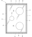
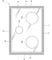
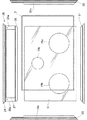
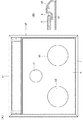
図1〜4において、本発明のコンロ用天板は、前枠片1、後枠片2、左枠片3及び右枠片4のアルミサッシ枠片から構成される金属枠体5と、化粧用耐熱性ガラス板6と、ガラス板6の外周縁を嵌合する耐熱性のシリコーンゴム製パッキン7と、ガラス板6を金属枠体5に支持する固定具8とからなる。
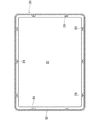
各枠片1〜4は、断面形状がコ字状をなし、開口溝9を形成する上片1a〜4aと側片1b〜4bと下片1c〜4cとから構成される。側片1b〜4bの厚みにはネジ止め用溝1d〜4dが形成されている。各枠片の上片1a〜4a及び下片1c〜4cの長手方向両端は開口溝9側である内方に向かって幅狭となるように45°の角度で傾斜していて、これら上下片と隣接する枠片の上下片を接合することにより、外観に優れた額縁状の金属枠体5が形成される。なお、図3(A)中の1e〜4eは、各枠片の上片1a〜4aの外縁から連続的に外方へつながる外周飾り面部である。これらの下端は、図4(C)の想像線に示すように、カウンタートップAに載置され、天板はコンロ本体Bの上面開口を覆う。
ガラス板6には、大火力バーナ、中火力バーナ及び弱火バーナが臨むバーナ用開口10a,10b,10cが形成されている。バーナ用開口10の数は、3つに限定されるものではなく、カスタマーのニーズ等に応じて適宜設定される。また、パッキン7は、断面形状がコ字状をなし、凹溝7mを形成する上側片7aと側部片7bと下側片7cとから構成される。固定具8は、図4(A)に示すように、ベース状の水平部8aとその側縁から上方に延びる2つの垂直部8bとから構成され、水平部8aの内方側端部に2つのネジ孔11が穿孔されている。
【0016】
以上の構成部材を用いてコンロ用天板が次のようにして組み立てられる。
予めガラス板6の外周縁をパッキン7の凹溝7mに嵌合しておく。その後、隣接する枠体同士、例えば後枠片2及び左枠片3の隣接する各一端を互いに当接し、更に固定具の水平部8aを枠片の下片2c,3c下面に当接させながら、垂直部8bを枠片の側片2b,3b外面に当接させて、固定具8に穿孔されたネジ孔11からネジ12を枠片の溝2d,3d内に差し込むことにより、固定具8が枠片2,3にネジ止めされる。
次に、外周縁にパッキン7が装着されたガラス板6の2側縁を枠片2,3の開口溝9,9内に嵌入させた後、ガラス板6の他の2側縁を前枠片1及び右枠片4の開口溝9,9内に嵌入させ、枠片1,4の各一端を枠片2,3の他端に接合させると共に枠片1,4の他端同士を互いに接合させる。この状態で、上述と同様にして、枠片2,4、枠片1,3及び枠片1,4の各端部裏面から固定具8を宛ってネジ止めすることにより、コンロ用天板が組み立てられる。
このようにして、固定具の垂直部8bを天板の内側方向に押し当てることによって、ガラス板6を金属枠体5に正確に取り付けることが可能である。なお、上記コンロ用天板の組立については、外周縁がパッキン7に嵌合されたガラス板6の2側縁を枠片2,3の各開口溝9内に先に嵌入させ、次いで固定具8を枠片2,3にネジ止めした後に、枠片1,4の各開口溝9内にガラス板6の他の2側縁を嵌入させる等であってもよい。
【0017】
本発明のコンロ用天板は、ガラス板6に開設されるバーナ用開口10の数以外にも、枠片1〜4の構造、パッキン7の寸法幅及び固定具8の構造等について種々変更することが可能である。
例えば、図5に示すように、各枠片の両端を傾斜させることなく長手方向と幅方向を直交させててもよい。この場合、前後枠片1,2及び左右枠片3,4の一方の両端が露呈するので、エンドピースで接合部分を被覆することが好ましい。
また、各枠片の上片1a〜4aと外周飾り面部1e〜4eが45°の傾斜接合でありながら(図3(A)参照)、各枠片の下片1c〜4cでは一端に切欠部13を形成し、これらの他端に切欠部13に係合する係合部14を形成して、隣接する下片1c〜4cの端部同士を係合接合とすることができる。あるいは、図6に示すように、前後枠片1,2及び左右枠片3,4の一方の枠片の各下片の両端部に切欠部13を形成し、他方の枠片の各下片の両端部に同切欠部13に係合する係合部14を形成してもよい。このように、隣接する枠片の端部同士の接合において、上片同士は傾斜接合でありながら下片同士を係合接合とすると、上片1a〜4aは傾斜接合で外観に優れた金属枠体5に形成できると共に、下片1c〜4cは係合接合であるので端部同士の接合が強固なものとなる。
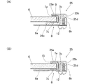
【0018】
外観上の観点から、一般に各枠片の上片1a〜4aの幅を短くしたものがカスタマーに好まれる傾向にある。その場合、下片1c〜4cを上片1a〜4aと同じ幅とすると、金属枠体5によるガラス板6の保持力が低下するので、例えば図4(B),(C)に示すように、下片1c〜4cの幅を上片1a〜4aの幅より長くすることが好ましい。同時に、パッキンの下側片7cも下片1c〜4cに応じて幅広とする。これによれば、ガラス板6の外周縁をパッキンの凹溝7mに嵌入しやすい利点がある。
パッキンの上側片7a端面を隠蔽させるために、図7に示すように、各枠片の開口溝9に沿って上片1a〜4aの内端縁に下方に突出する突条15を形成することが好ましい。パッキン7に煮汁等が浸入しないように、突条15をガラス板6表面に当接させることが好ましい。また、各枠片の開口溝9に沿って下片1c〜4cの内端部にコンロの内方に向かって下降する傾斜面16を形成することが好ましい。特に突条15を形成した場合、傾斜面16を形成しておくと、パッキン7が装着されたガラス板6の外周縁を金属枠体5の開口溝9内にスムーズに嵌入することができる。
【0019】
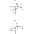
本発明においては、図8(A)に示すように、固定具の水平部8a及びパッキンの下側片7cの各内端を枠片の下片1c〜4cの内端より内方に延在させて、下片1c〜4cより内方に延在する水平部8aに支え手段として上方に膨出する凸状の段部17を形成して、段部17とガラス板6との間にパッキンの下側片7cを介在させると、パッキンの下側片7c下面に接する下片1c〜4cの接触面が小さくても、段部17が形成された水平部8aを介してガラス板6を金属枠体5に確実に支持することができる。この場合、段部17とガラス板6との間にパッキンの下側片7cが介在するので、ガラス板6を傷付けることがない。
また、図8(B)に示すように、固定具の水平部8aの内端を枠片の下片1c〜4c及びパッキンの下側片7cの各内端より内方に延在させて、下片1c〜4c及び下側片7cより内方に延在する水平部8aの上面とガラス板6の裏面との間に支え手段として緩衝材18を介在させてもよい。この場合も同様に、緩衝材18を介してガラス板6を金属枠体5に確実に支持することができ、ガラス板6の裏面を傷付けることがない。更に、水平部8aに上方に膨出する段部17を形成して、ガラス板6裏面と段部17との間に緩衝材18を介在させてもよい。
【0020】
本発明は、図3に示すコンロ用天板において、各枠片1〜4の下片を取り除いた枠体から金属枠体5を形成することができる。このコンロ用天板の要部縦断面図を図9(A)に示している。図示の天板は、固定具の水平部8aがパッキンの下側片7cの下面に当接し、その垂直部8bが隣接する枠片の各側片(1b,3b;3b,2b;2b,4b;4b,1b)の外面に当接して、固定具8が枠片1〜4にネジ止めされている。
下片1c〜4cを具備しない枠片からなる図9(A)に示すコンロ用天板は、先に示した下片1c〜4cを具備する枠片からなる天板の変更例を適用することが可能である。
例えば、図9(B)に示すように、図4(A)に示す垂直部8bの各外端を結ぶ線から直角部分を含む水平部8aを取り除いた固定具8とすることもできる。また、固定具の水平部8aの内端をパッキンの下側片7cの内端より内方に延在させて、下側片7cより内方に延在する水平部8aの上面とガラス板6の裏面との間に前記支え手段(17,18)を介在させてもよい。これらの場合も、ガラス板6を確実にかつ所定の位置に正確に配置することが可能である。
【0021】
本発明は、ガラス板の後方に開口部を形成したコンロ用天板に変更することができる。
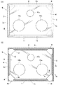
図10〜15において、上記コンロ用天板は、前枠片21、左枠片22、右枠片23の各枠片及び主後枠片24と副後枠片25との間に開口部27を形成した後枠28から構成される金属枠体26と、化粧用耐熱性ガラス板6と、ガラス板6の外周縁を嵌合する耐熱性のシリコーンゴム製パッキン7と、枠片21〜23,25を連結する固定具8と、主後枠片24を左右枠片22,23に連結する連結具29とからなる。上記枠片21〜25はアルミサッシ枠片で構成される。ここで、前枠片21、主後枠片24、ガラス板6、パッキン7及び固定具8の各構成部材は前述したものと実質的に同じであるので、主として図3に示すコンロ用天板と異なる点について以下に説明する。
副後枠片25は、断面形状がコ字状をなし、開口溝を形成する上片25aと側片25bと下片25cとから構成される。側片25bの厚みにはネジ止め用の溝25dが形成されている。また、図3(A)の例と同様に、枠片の上片21a〜24a及び下片21c〜24cの両端は内方に向かって幅狭となるように45°の角度で傾斜していて、これらの上下片と隣接する上下片との端部同士を傾斜接合することにより、額縁状の金属枠体26が形成される。
【0022】
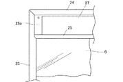
副後枠片の上片25a及び主後枠片の上片24aは側部28a,28aで連結されて一体となっており、後枠28にはその左右側部を残してほぼ全域にグリル用排気口等の開口部27が開設されている。なお、主後枠片24と副後枠片25とは一体化されているが、分離可能な別体とすることもできる。左右枠片の上片22a,23a及び下片22c,23cは、ガラス板6の左右外周縁を支持する部分が、即ち副後枠片25の前方側がその後方より幅広であり、幅広部分の各後端に副後枠片25の両端が接合される。副後枠片の下片25c両端は、その一端が図14に示されているように、上片25aと異なって角部が斜めに切り欠かれている。この切欠部分に対応して、左右枠片の下片22c,23cの幅広部分後端は、上記切欠部分に係合する形状に形成されている。
以上のような副後枠片25の開口溝内に、パッキン7の凹溝に嵌合されたガラス板6の後外周縁が嵌合される。また、ガラス板6裏面の4隅は、図4(A)に示すような固定具8を介して、前枠片21、左右枠片22,23及び副後枠片25が連結される。その中のガラス板6が副後枠片25に支持される状態を図15に示す。図15(A)は副後枠片25に下片25cを有する場合の断面図であり、図15(B)は副後枠片25に下片を備えていない場合の断面図である。一方、連結具29は、主後枠片24の両端部を左右枠片22,23に連結するために用いられ、図4(A)に図示する固定具と同じ形状をなる。
【0023】
本発明は、また、板金プレス加工によって金属枠体を一体成形することができる。
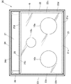
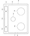
図16〜19において、符号31はステンレス鋼製の金属枠体であり、平板に窓穴33が形成され、その外周部32が額縁状に形成されている(図16,19参照)。窓穴33には、外周縁が前記シリコーンゴム製パッキン7の凹溝に嵌合された化粧用耐熱性ガラス板6が取り付けられる。ガラス板6には、前記バーナ用開口10a,10b,10cが形成されている。
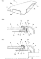
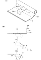
金属枠体の外周部32は、図18(A),図19(B)に示すように、下方に傾斜する傾斜面34とそれから下方に折曲する垂直面を有すると共に、垂直面の下端から内側に折曲ないしは湾曲していて、外周部32の下方に取付部35が一体的に設けられている。取付部35は水平片35aと垂直片35bとから構成され、水平片35aにはネジ孔36が穿孔されている。この取付部35は、水平片35a及び垂直片35bが予め形成されている各外周部32を順次または同時にプレス加工することにより、外周部32の下方の所定の位置に設けられる。具体的には図18(B)に示すように、外周部32を緩やかに折曲し、更に下方に折曲して外周壁部を形成した後、内方にカール状に湾曲させることによって、外周部32の下側に所定の数の取付部35が形成される。図16には、金属枠体31の前後側縁部に3個及び左右側縁部に2個の取付部35を設けた例が図示されている。
【0024】
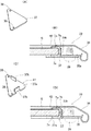
パッキン7の凹溝に嵌合されたガラス板6は、固定具37を介して金属枠体31に支持される。固定具37は、図19(A)に示すように、直角二等辺三角形の板材から構成され、その角部に2つのネジ孔38が穿孔されている。
上記固定具37は、図19(B)に示されるように、取付部の水平片35a裏面に一部を重ね合わせてパッキンの下側片7cの下面に当接させる。そして、パッキン7が装着されたガラス板6は、パッキンの側部片7bの外面を取付部の垂直片35bに当接させることにより位置決めされ、固定具37のネジ孔38と取付部35のネジ孔36とを位置合わせして、ネジ39で固定具37を取付部35にネジ止めすることにより、ガラス板6が金属枠体31に支持される。ガラス板6を金属枠体31に位置決めする際、取付部の垂直片35bは、パッキンの側部片7bの外面に当接するので、ガラス板6の位置決め部材となり、ガラス板6を所定の位置に正確に配置することができる。
図16に示す金属枠体31においては、ガラス板6の位置決め部材として、図19(C),(D)に示すように、上記取付部の垂直片35bに代えて固定具37に設けられた垂直部37bを利用することもできる。即ち、取付部35は垂直片35bを具備しておらず、一方、固定具として、直角二等辺三角形の水平部37aと二等辺の中央部の切欠から上方に延びる2つの垂直部37bとから構成され、水平部37aの角部に2つのネジ孔38が穿孔された固定具37を用いる。
この固定具37を用いる場合は、パッキン7が装着されたガラス板6は、次のようにして金属枠体31に支持される。取付部の水平片35a裏面に一部が重ね合わされる固定具37は、まずその水平部37aをパッキンの下側片7cの下面に当接させると共に、垂直部37bを側部片7bの外面に当接させる。そして、固定具37のネジ孔38と取付部35のネジ孔36とを位置合わせして、ネジ39で固定具37を取付部35にネジ止めすることにより、ガラス板6が金属枠体31に支持される。
他方、ガラス板6の前後側縁中央部は、板状の固定金具40のネジ孔及び水平部35aのネジ孔36に挿通されるネジ41で固定金具40を取付部35にネジ止めすることにより、金属枠体31に支持される(図17(B)参照)。なお、外周部32の内側部分を内方に向けてやや下降させ、窓穴33に沿ってその内端縁に下方に突出する突条42を形成することが好ましい。
【0025】
本発明は、図17に示す天板をガラス板の後方にグリル用排気口または吸気口となる開口部を形成したコンロ用天板に変更することができる。
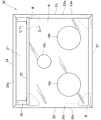
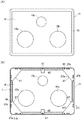
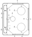
図20〜22において、上記コンロ用天板は、板金プレス加工によって平板に窓穴33及び3つの開口部43が形成され、その外周部32を額縁状に形成した金属枠体44と、前記ガラス板6と、ガラス板6の外周縁を嵌合する前記パッキン7と、ガラス板6を金属枠体44に支持する固定具37と、ガラス板6の前後側縁中央部を支持する固定金具40とからなる。以下に、図17に示すコンロ用天板と異なる点について主として説明する。
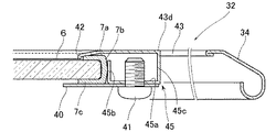
金属枠体44の外周部32はその後側が前側及び左右側より幅広の後部側辺を備え、この後部側辺には、グリル用排気口または吸気口となる上記開口部43が形成されている。開口部43は、細長い中央開口43a及びその左右の小開口43b,43cから構成される。また、金属枠体44の窓穴33には、パッキン7が装着されたガラス板6が配設される。窓穴33の後側には、3つの取付部45が各開口43a〜43cの前側縁下方に設けられている(図21参照)。その構造を図22に示す。
これらの取付部45は、距離が長い等の理由で外周部32の後縁から延出することが困難であるので、開口部43を形成する際に、その窓穴側開口縁43dに開口部分となる板金を利用して形成される。即ち、取付部45は、開口43a〜43cの各窓穴側開口縁43dから下方に延びる垂下片45cと、その下端から窓穴33側に延びる水平片45aと、その先端から上方に延びる垂直片45bとから一体に構成される。水平片45aにはネジ孔が穿孔され、パッキンの側部片7bの外面に当接する垂直片45bはガラス板6の位置決め部材となる。この場合の左右隅部の固定具は、図19(A)に示す固定具37が採用される。
図21の例では、前側の左右隅部にも同じ固定具37が採用されており、取付部は外周部32の前側、左側、右側も含め全て図19(B)のように垂直片35bを備えている。
【0026】
なお、取付部45の変形例として、外周部32の前側、左右側も含め垂直片45bを具備していない取付部であってもよく、この場合の上記固定具は、図19(C)に示す固定具37が採用される。
以上のコンロ用天板においては、取付部の垂直片35b,45bまたは固定具の垂直部37bがパッキン7を装着したガラス板6の外周位置決め部材となるので、ガラス板6を所定の位置に正確に配設することができる。
各実施態様において、パッキン7が環状体である場合の例で説明したが、凹溝を有する断面形状がコ字状の直線状パッキンをガラス板6の外周に巻いて取り付けることもできる。更に、取付部35,45は、金属枠体31,44に一体に設けられた例を説明したが、外周部32の前述と同様な箇所に別体して取り付けることもできる。
【0027】
【発明の効果】
本発明は、シール部材として断面コ字状のパッキンを用いているので、パッキンをガラス板外周縁に容易に取り付けることができる。また、パッキンを外周縁に装着したガラス板は固定具によって金属枠体に支持されるものであるから、ガラス板と金属枠体とのシール性が充分に確保され、コンロ用天板の生産性が安定化する。そのため、ガラス天板の歩留まりが向上する。更に、ガラス板の外周縁を保護するシール部材がパッキンであるため、コンロ用天板を廃棄処分する際、金属枠体及び付属の金属部品、ガラス板、シール部材の各部材を分別回収することができる。
また、プレス加工によって一体成形された金属枠体を用いた場合は、金属枠体の製造が簡素化され、ガラス板を金属枠体に容易に装着することができる。
【図面の簡単な説明】
【図1】コンロ用天板の枠部材として金属枠片を用いた本発明の各構成部材を示す裏面図である。
【図2】図1に示す構成部材の配置状態を説明する裏面図である。
【図3】(A)は図2に示す構成部材を固定具によって固定した状態を説明する本発明の天板の平面図であり、(B)はその裏面図である。
【図4】(A)は固定具の斜視図である。また、(B),(C)は本発明におけるガラス板の固定状態を示す要部拡大図であって、それぞれ図3(B)のA−A線截断図及びB−B線截断図である。
【図5】コンロ用天板の枠部材として別の金属枠片を用いた本発明の天板の平面図である。
【図6】(A)は更に別の枠片同士の接合状態の一例を示す裏面図であり、(B)はその接合前の状態を示す裏面図である。
【図7】本発明におけるガラス板の固定方法の一例を示す要部拡大図であり、(A)はパッキンが装着されたガラス板の側縁を金属枠片の開口溝に挿入する時の状態を示し、(B)はガラス板が金属枠体に固定された状態を示す。
【図8】(A),(B)はそれぞれ本発明におけるガラス板の固定状態を示す他の要部拡大図である。
【図9】(A)はコンロ用天板の枠部材として他の金属枠片を用いた本発明におけるガラス板の固定状態を示す縦断面図であり、(B)はガラス板の固定に用いられる別の固定具の斜視図である。
【図10】グリル排気口等を備えた本発明のコンロ用天板の各構成部材を示す裏面図である。
【図11】図10に示す構成部材の配置状態を説明する裏面図である。
【図12】図11に示す構成部材を固定具及び連結具によって固定した状態を説明する本発明の天板の裏面図である。
【図13】図12の平面図である。
【図14】副後枠片と右枠片との接合状態の一例を示す裏面図である。
【図15】(A)は図13のC−C線截断図であり、(B)は下片を備えていない金属枠片の図15(A)に対応する断面図である。
【図16】プレス加工によって一体成形された金属枠体の裏面図である。
【図17】(A)は図16に示す金属枠体を用いた本発明の一例を示す平面図であり、(B)はその裏面図である。
【図18】(A)は図16に示す金属枠体の外周部の一部及び取付部の斜視図であり、(B)は取付部の加工手順を示す概略説明図である。
【図19】(A),(C)はガラス板の角部に取り付けられる固定具の斜視図である。また、(B),(D)はそれぞれガラス板の固定状態を示す要部拡大図であって、そのうちの(D)は図17(B)のD−D線截断図である。
【図20】プレス加工によって一体成形され、グリル排気口等を備えた金属枠体を用いた本発明の一例を示す平面図である。
【図21】図20の裏面図である。
【図22】図21のE−E線截断図である。
【図23】(A)は枠部材としてアルミ枠を用いた従来のガラス天板の平面図であり、(B)はその要部断面図である。
【図24】(A)は枠部材としてステンレス枠を用いた従来のガラス天板の平面図であり、(B)はその要部断面図である。
【図25】(A)及び(B)はそれぞれ別の従来のガラス天板の要部断面図である。
【符号の説明】
1,21・・・ 前枠片、2・・・ 後枠片、3,22・・・ 左枠片、4,23・・・ 右枠片、1a〜4a・・・ 上片、1b〜4b・・・ 側片、1c〜4c・・・ 下片、5,26,31,44・・・ 金属枠体、6・・・ ガラス板、7・・・ パッキン、7a・・・ 上側片、7b・・・ 側部片、7c・・・ 下側片、7m・・・ 凹溝、8,37,40・・・ 固定具、8a・・・ 水平部、8b・・・ 垂直部、9・・・ 開口溝、13・・・ 切欠部、14・・・ 係合部、15・・・ 突条、16・・・ 傾斜面、17・・・ 段部(支え手段)、18・・・ 緩衝材(支え手段)、24・・・ 主後枠片、25・・・ 副後枠片、27,43・・・ 開口部、32・・・ 外周部、33・・・ 窓穴、35,45・・・ 取付部、45a・・・ 水平片、45c・・・ 垂下片。[0001]
TECHNICAL FIELD OF THE INVENTION
The present invention relates to a stove top such as a drop-in stove incorporated in a system kitchen. More specifically, the present invention relates to a stove top plate in which an outer peripheral edge of a glass plate is fitted with packing having a U-shaped cross section.
[0002]
[Prior art]
2. Description of the Related Art Drop-in type stoves, in which a glass top plate is attached to the upper surface of a stove body having a heating source such as a gas burner inside, are becoming popular in ordinary households. The heat-resistant glass plate for makeup in such a glass top plate is provided with a rubber sealing member on the outer peripheral portion thereof to prevent damage to the outer peripheral edge of the glass plate and infiltration of boiling water into the stove body. ing.
As a conventional sealing method of the outer peripheral edge of the glass plate, a method of pouring a silicone rubber adhesive into a gap formed between the outer periphery of the glass plate and the upper edge of the top plate is known. FIGS. 23 and 24 show an example thereof. Reference numerals a1 and a2 in the drawings denote left and right front and rear aluminum sash pieces and a stainless steel plate material formed by press working, and a frame shape forming a top plate. This shows the frame body. Openings b1 and b2 are formed at the rear of the frame body a as grill exhaust ports and intake ports. Further, an opening or a window hole in which the glass plate c is mounted is formed in the frame-shaped frame body a. Openings d1, d2 and d3 facing the burner head are perforated in the glass plate c, and the glass plate c is supported on the lower piece e1 of the frame a1 or on the bottom surface e2 of the frame a2. A gap is formed between the outer periphery of the glass plate c and the frame body a. The silicone rubber adhesive f is poured into these gaps and then cured to protect the outer periphery of the glass plate c.
[0003]
In the above-mentioned sealing method, not only is it difficult to stably supply the silicone rubber adhesive (coating agent) poured into the gap, but also it is difficult to fill the coating agent uniformly. Was. In order to facilitate the filling of the coating agent, as shown in FIG. 25, a step g is provided on the upper edge of the top plate a and the upper portion of the glass plate c or an inclined surface h is provided, so that the gap is formed at the lower portion. A kitchen appliance having a wider upper portion is known (see Patent Document 1).
On the other hand, there is known a drop-in type cooker in which a hot plate is attached to an opening of a top plate and a lower edge of an outer peripheral portion of the top plate is placed and supported on a countertop (see Patent Document 2). In this cooker, a sealing material is attached to the periphery of the hot plate, and a horizontal holding frame integral with the hanging plate extending downward in the main body is screwed to a reinforcing frame spot-welded to the lower surface of the periphery of the top plate. During screwing, the hot plate is pinched and fixed to the lower surface of the outer peripheral edge of the opening via a sealing material.
[0004]
[Patent Document 1]
Japanese Utility Model Publication No. 5-31956 (FIGS. 3 and 5)
[Patent Document 2]
Japanese Utility Model Publication No. 60-22244 (FIG. 5)
[0005]
[Problems to be solved by the invention]
However, in the conventional sealing method in which the coating agent is poured, it takes about one day to cure the silicone rubber coating agent, and a storage space such as a clean room is required during that time. In addition, a difference in finish of the cured coating agent occurs due to a difference in the speed of pouring the coating agent and the room temperature. As a result, irregularities may be formed on the cured surface, or the coating agent may protrude onto the glass plate, and in some cases, the sealing property between the glass plate and the top plate frame may not always be sufficient. Regarding this point, the kitchen appliance disclosed in Patent Document 1 has the same problem because the supply amount of the coating agent is not actively stabilized. Further, when the cooking utensil having the glass top plate is disposed of, the glass plate is fixed to the frame with the coating agent, so that there is a problem that the collection and separation cannot be performed.
On the other hand, in the cooking device of Patent Document 2, since the reinforcing frame is spot-welded to the lower surface of the peripheral edge of the top plate, traces of spot welding remain on the surface of the top plate, and the appearance of the top plate is significantly impaired. Therefore, applying the fixing means of the hot plate of Patent Document 2 in which the peripheral edge of the hot plate is sandwiched between the reinforcing frame and the holding frame via the sealing material to the decorative glass top plate requires an external appearance. There's a problem.
[0006]
Therefore, an object of the present invention is to solve the above-mentioned problems of the prior art, and first of all, a seal for preventing the outer peripheral edge of the glass plate from being damaged without damaging the appearance of the top plate. An object of the present invention is to improve the productivity of a glass top plate by simplifying an operation of attaching members. Next, an object is to improve the yield by stabilizing the productivity of the glass top plate having the sealing property with the top plate frame. It is another object of the present invention to separate and collect a glass plate, a top plate frame, and a seal member when disposing of a stove having a glass top plate. The present invention seeks to provide such a stove top plate.
[0007]
[Means for Solving the Problems]
The stove top plate according to the first aspect of the present invention connects a front frame piece, a rear frame piece, a left frame piece, and a right frame piece having a U-shaped cross section having an upper piece, a side piece, and a lower piece, respectively, with a fixture. A frame-shaped metal frame formed as described above and a glass plate fixed to the metal frame via a seal member, and the seal member is formed of a U-shaped packing having a concave groove and a cross-sectional shape. The outer edge of the glass plate is fitted in the concave groove of the packing, and the outer edge of the glass plate covered with the packing is fitted in the opening groove having a U-shaped cross section of the metal frame. Are supported by the metal frame by the fixture.
The stove top plate of the invention according to claim 6 is configured such that a front frame piece, a rear frame piece, a left frame piece, and a right frame piece each having an inverted L-shaped cross section having an upper piece and a side piece are connected by a fixture. A frame-shaped metal frame to be formed, and a glass plate fixed to the metal frame via a sealing member, the sealing member is formed of a U-shaped packing having a concave groove and a cross-sectional shape. The outer peripheral edge of the plate is fitted into the groove of the packing, and the upper piece and the side piece of the packing are brought into contact with the lower surface of each upper piece of the metal frame and the inner surface of the side piece, and the glass plate is fixed to the fixing tool. Characterized by being supported by the metal frame.
[0008]
The stove top plate according to the ninth aspect of the present invention is arranged such that a window hole is formed by integral molding by press working and a metal frame body having an outer peripheral portion formed in a frame shape and a window hole of the metal frame body via a seal member. The sealing member is formed of a U-shaped packing having a concave groove, the outer peripheral edge of which is fitted in the concave groove of the packing, and the lower side of the packing. The glass plate is supported by the metal frame via a fixing member that contacts the lower surface of the piece.
[0009]
[Action]
In the stove top plate according to the first aspect of the present invention, since the seal member is formed of packing having a U-shaped cross section, the packing as the seal member can be easily attached to the outer peripheral edge of the glass plate. Therefore, the productivity of the glass top plate is improved as compared with the case where a coating agent is used. Further, the outer peripheral edge of the glass plate is fitted in the concave groove of the packing, and the glass plate is supported by the metal frame by the fixture with the outer peripheral edge fitted in the opening groove of the metal frame. Therefore, the sealing property between the glass plate and the metal frame is sufficiently ensured, the productivity of the stove top plate is stabilized, and the yield is improved. Moreover, since there is no need to attach a reinforcing frame to the lower surface of the outer periphery of the top plate, the appearance of the top plate is not impaired. Furthermore, since the seal member that protects the outer peripheral edge of the glass plate is a packing, when the stove top plate is discarded, it is possible to separate and collect the glass plate, the metal frame, and the seal member. .
[0010]
According to the invention according to claim 2, the joining between the adjacent ends of the respective frame pieces of the metal frame body is inclined bonding in the upper piece, and the lower piece forms a cutout in one frame piece and the other. An engaging portion that engages with the notch portion is formed on the frame piece to form an engaging joint. As described above, since the ends of the upper pieces are inclinedly joined, the metal frame can be formed in a frame shape having an excellent appearance. In addition, since the lower pieces are engaged by joining while the upper pieces are inclined, the joining of the adjacent lower pieces can be easily performed, and the joining of the ends becomes strong.
According to the third aspect of the present invention, since the protrusion protruding downward is formed along the opening groove at the inner end edge of the upper piece of each frame piece, the packing is concealed and the appearance of the top plate is improved. I do. Also, since an inclined surface descending inward is formed along the opening groove at the inner end of the lower piece of each frame piece, the outer peripheral edge of the glass plate on which the packing is mounted is formed by the opening groove of the metal frame. It can be easily fitted into the inside, and the workability at the time of manufacturing the top plate is improved.
[0011]
According to the invention according to claim 4, the horizontal portion of the fixing tool abuts against the lower surface of each lower piece of the adjacent frame piece of the metal frame, and the vertical portion of the fixing tool has the outer surface of each side piece of the adjacent frame piece. And the fixture is screwed to each frame piece. Therefore, the glass plate fitted in the opening groove of the metal frame via the packing can be accurately arranged at a predetermined position, and the glass plate is reliably supported by the metal frame.
According to the invention according to claim 5, the inner end of the horizontal portion of the fixture extends inward from the inner end of the lower piece of the frame piece, and is supported on the horizontal portion extending inward from the lower piece. And the glass plate is supported. Therefore, even if the area of the lower piece of the metal frame is reduced, the glass plate can be reliably supported on the metal frame via the support means formed on the horizontal portion. Here, when the lower piece of the packing extends inward from the inner end of the lower piece of the frame piece, for example, a convex step portion abutting on the lower surface of the lower piece of the packing is used as a support means. In this case, since the outer peripheral edge of the glass plate is protected by the packing, the rear surface of the glass plate is not damaged. In addition, if a buffer material is interposed between the horizontal portion and the glass plate, the back surface of the glass plate will not be similarly damaged.
[0012]
The stove top plate of the invention according to claim 6 simplifies the structure of each frame piece in the invention according to claim 1 in that each frame piece of the metal frame does not have a lower piece. However, similarly to the present invention, the packing can be easily attached to the outer peripheral edge of the glass plate, and separate collection can be performed without impairing the appearance of the top plate. Further, the glass plate is supported by the metal frame by a fixing tool in a state where the upper piece and the side piece of the packing are in contact with the lower surface of each upper piece and the inner surface of the side piece of the metal frame. Therefore, the sealing property between the glass plate and the metal frame is ensured, and the productivity of the stove top plate is stabilized, so that the yield of the glass top plate is improved.
According to the invention according to claim 7, the horizontal part of the fixing tool abuts on the lower surface of the lower piece of the packing, and the vertical part of the fixing tool abuts on the outer surface of each side piece of the adjacent frame piece. Is screwed to each frame piece, so that the glass plate can be accurately arranged at a predetermined position, similarly to the invention according to claim 4.
According to the invention according to claim 8, the rear frame piece of the metal frame is provided with the main rear frame piece arranged at the rear part and the sub rear frame piece arranged at the front part with an interval, and is covered with packing. The rear outer edge of the glass plate abuts against the inner surface of the side piece of the sub-rear frame piece, and an opening is formed between the upper pieces of the main rear frame piece and the sub-rear frame piece, so that the opening It can be used as a top plate for a stove provided with a grill whose part is a grill outlet or inlet.
[0013]
In the stove top plate according to the ninth aspect of the present invention, a metal frame having a frame-shaped outer peripheral portion is integrally formed by press working, and a glass plate having the packing mounted on the outer peripheral edge is disposed in a window hole of the metal frame. Since it is provided, not only the manufacture of the metal frame is simplified, but also the mounting of the glass plate on the metal frame is easy. Further, similarly to the invention according to the first aspect, the packing can be easily attached to the outer peripheral edge of the glass plate without impairing the appearance of the top plate, and the sealing property between the glass plate and the metal frame is ensured, Separate collection is possible. Further, since the glass plate is supported by the metal frame via the fixing tool which abuts on the lower surface of the lower piece of the packing, the glass plate can be reliably supported by the metal frame.
According to the invention according to claim 10, the outer peripheral portion of the metal frame is bent inward, and a mounting portion is provided integrally with the metal frame below the outer peripheral portion, and the fixing tool is screwed to the mounting portion. Have been. Therefore, not only is the appearance of the frame-shaped metal frame excellent, but also it is not necessary to separately provide a mounting member, so that the number of parts can be reduced. In addition, the glass plate can be easily supported by the metal frame by screwing the fixing member to the mounting portion.
[0014]
According to the invention according to claim 11, an opening is formed in the outer peripheral portion of the rear portion of the metal frame, and the opening is formed by a hanging piece on the window hole side opening edge and a horizontal piece extending from the lower end to the window hole side. An attachment portion is integrally provided, and a fixing tool is screwed to the attachment portion. Therefore, it can be used as a stove top provided with a grill whose opening is a grill outlet or inlet. Further, similarly to the invention according to claim 10, the number of parts is reduced. Furthermore, it is also possible to form a vertical piece extending upward from the horizontal piece of the mounting portion, and use this vertical piece as a positioning member for the glass plate on which the packing is mounted.
According to the twelfth aspect of the present invention, the horizontal part of the fixing tool abuts the lower surface of the lower piece of the packing, and the vertical part of the fixing tool abuts the outer surface of the side piece of the packing. As in the invention according to the first aspect, the glass plate can be reliably supported.
According to the invention according to claim 13, the horizontal piece of the mounting portion abuts the surface of the horizontal portion of the fixture, the vertical piece of the mounting portion abuts the outer surface of the side piece of the packing, The glass plate can be accurately positioned, and the glass plate is positioned at a predetermined position.
[0015]
BEST MODE FOR CARRYING OUT THE INVENTION
Hereinafter, the present invention will be described in detail with reference to the drawings.
1 to 4, a stove top plate according to the present invention includes a metal frame 5 composed of an aluminum sash frame piece of a front frame piece 1, a rear frame piece 2, a left frame piece 3 and a right frame piece 4; It comprises a heat-resistant glass plate 6 for use, a heat-resistant silicone rubber packing 7 for fitting the outer periphery of the glass plate 6, and a fixture 8 for supporting the glass plate 6 on the metal frame 5.
Each of the frame pieces 1 to 4 has a U-shaped cross section, and includes upper pieces 1a to 4a, side pieces 1b to 4b, and lower pieces 1c to 4c that form the opening groove 9. Screws 1d to 4d are formed in the thickness of the side pieces 1b to 4b. Both ends in the longitudinal direction of the upper pieces 1a to 4a and the lower pieces 1c to 4c of each frame piece are inclined at an angle of 45 ° so as to become narrower inward on the opening groove 9 side. By joining the upper and lower pieces of the adjacent frame pieces, a frame-shaped metal frame body 5 having an excellent appearance is formed. In addition, 1e-4e in FIG. 3 (A) is an outer peripheral decoration surface part continuously connected outward from the outer edge of the upper pieces 1a-4a of each frame piece. These lower ends are placed on the counter top A as shown by the imaginary line in FIG. 4C, and the top plate covers the upper opening of the stove body B.
The glass plate 6 is provided with burner openings 10a, 10b, and 10c facing the large, medium and low-fire burners. The number of the burner openings 10 is not limited to three, and is appropriately set according to customer needs and the like. The packing 7 has a U-shaped cross section, and includes an upper piece 7a, a side piece 7b, and a lower piece 7c that form a concave groove 7m. As shown in FIG. 4 (A), the fixing tool 8 is composed of a base-shaped horizontal portion 8a and two vertical portions 8b extending upward from the side edges thereof, and is provided at the inner end of the horizontal portion 8a. Two screw holes 11 are drilled.
[0016]
The stove top plate is assembled as follows using the above components.
The outer peripheral edge of the glass plate 6 is fitted in the groove 7m of the packing 7 in advance. Then, adjacent frame bodies, for example, adjacent one ends of the rear frame piece 2 and the left frame piece 3 abut against each other, and furthermore, the horizontal portion 8a of the fixing tool abuts on the lower surfaces of the lower pieces 2c and 3c of the frame piece. The vertical portion 8b is brought into contact with the outer surface of the side piece 2b, 3b of the frame piece, and a screw 12 is inserted into the groove 2d, 3d of the frame piece from the screw hole 11 drilled in the fixture 8, thereby fixing the fixture 8 Are screwed to the frame pieces 2 and 3.
Next, after the two side edges of the glass plate 6 having the packing 7 mounted on the outer peripheral edge are fitted into the opening grooves 9, 9 of the frame pieces 2, 3, the other two side edges of the glass plate 6 are connected to the front frame. The frame 1 and the right frame 4 are fitted into the opening grooves 9, 9, and one ends of the frame pieces 1 and 4 are joined to the other ends of the frame pieces 2 and 3, and the other ends of the frame pieces 1 and 4 are mutually connected. Join. In this state, the fasteners 8 are screwed from the back surfaces of the ends of the frame pieces 2 and 4, the frame pieces 1 and 3, and the frame pieces 1 and 4 in the same manner as described above, so that the stove top plate is formed. Is assembled.
Thus, the glass plate 6 can be accurately attached to the metal frame 5 by pressing the vertical portion 8b of the fixture toward the inside of the top plate. In the assembling of the stove top plate, the two side edges of the glass plate 6 whose outer peripheral edge is fitted to the packing 7 are first fitted into the respective opening grooves 9 of the frame pieces 2 and 3, and then the fixing tool After the screws 8 are screwed to the frame pieces 2 and 3, the other two side edges of the glass plate 6 may be fitted into the respective opening grooves 9 of the frame pieces 1 and 4.
[0017]
The stove top plate of the present invention has various changes in the structure of the frame pieces 1-4, the dimensional width of the packing 7, the structure of the fixture 8, etc., in addition to the number of the burner openings 10 formed in the glass plate 6. It is possible.
For example, as shown in FIG. 5, the longitudinal direction and the width direction may be orthogonal to each other without inclining both ends of each frame piece. In this case, one end of each of the front and rear frame pieces 1 and 2 and the left and right frame pieces 3 and 4 is exposed. Therefore, it is preferable to cover the joining portion with an end piece.
In addition, although the upper pieces 1a to 4a of each frame piece and the outer peripheral decorative surface parts 1e to 4e are inclined at 45 ° (see FIG. 3A), the lower pieces 1c to 4c of each frame piece have cutouts at one end. 13 are formed, and the other end thereof is formed with an engaging portion 14 which engages with the cutout portion 13, so that the ends of the adjacent lower pieces 1c to 4c can be engaged with each other. Alternatively, as shown in FIG. 6, notches 13 are formed at both ends of each lower piece of one of the front and rear frame pieces 1 and 2 and the left and right frame pieces 3 and 4, and each lower piece of the other frame piece is formed. May be formed at both ends of the notch. In this way, when joining the ends of the adjacent frame pieces, the upper pieces are inclined joints and the lower pieces are engaged and joined together. In addition to being formed on the body 5, the lower pieces 1c to 4c are engaged and joined, so that the joining between the ends is strong.
[0018]
From the standpoint of appearance, customers generally tend to prefer those in which the width of the upper pieces 1a to 4a of each frame piece is reduced. In this case, if the lower pieces 1c to 4c have the same width as the upper pieces 1a to 4a, the holding force of the glass plate 6 by the metal frame 5 is reduced. For example, as shown in FIGS. It is preferable that the width of the lower pieces 1c to 4c is longer than the width of the upper pieces 1a to 4a. At the same time, the lower piece 7c of the packing is also made wider according to the lower pieces 1c to 4c. According to this, there is an advantage that the outer peripheral edge of the glass plate 6 can be easily fitted into the groove 7m of the packing.
In order to conceal the end face of the upper piece 7a of the packing, as shown in FIG. 7, a projecting ridge 15 projecting downward is formed on the inner edge of the upper piece 1a to 4a along the opening groove 9 of each frame piece. Is preferred. It is preferable that the ridges 15 be brought into contact with the surface of the glass plate 6 so that the boiling liquid or the like does not enter the packing 7. In addition, it is preferable to form an inclined surface 16 descending inward of the stove at the inner end of the lower pieces 1c to 4c along the opening groove 9 of each frame piece. In particular, when the ridge 15 is formed, if the inclined surface 16 is formed, the outer peripheral edge of the glass plate 6 on which the packing 7 is mounted can be smoothly fitted into the opening groove 9 of the metal frame 5.
[0019]
In the present invention, as shown in FIG. 8A, the inner ends of the horizontal portion 8a of the fixture and the lower piece 7c of the packing extend inward from the inner ends of the lower pieces 1c to 4c of the frame piece. Then, a convex step portion 17 bulging upward is formed as a support means on the horizontal portion 8a extending inward from the lower pieces 1c to 4c, and packing is provided between the step portion 17 and the glass plate 6. When the lower piece 7c is interposed, even if the contact surface of the lower pieces 1c to 4c in contact with the lower surface of the lower piece 7c of the packing is small, the glass plate 6 can be metallized via the horizontal portion 8a on which the step 17 is formed. It can be reliably supported on the frame 5. In this case, since the lower piece 7c of the packing is interposed between the step portion 17 and the glass plate 6, the glass plate 6 is not damaged.
As shown in FIG. 8 (B), the inner end of the horizontal portion 8a of the fixture extends inward from the inner ends of the lower pieces 1c to 4c of the frame piece and the lower piece 7c of the packing. A cushioning material 18 may be interposed between the upper surface of the horizontal portion 8a extending inward from the lower pieces 1c to 4c and the lower piece 7c and the back surface of the glass plate 6 as support means. In this case as well, similarly, the glass plate 6 can be reliably supported on the metal frame 5 via the cushioning member 18, and the rear surface of the glass plate 6 is not damaged. Further, a step portion 17 bulging upward may be formed in the horizontal portion 8a, and a buffer material 18 may be interposed between the back surface of the glass plate 6 and the step portion 17.
[0020]
According to the present invention, the metal frame 5 can be formed from the frame obtained by removing the lower pieces of the frame pieces 1 to 4 on the stove top plate shown in FIG. FIG. 9A is a longitudinal sectional view of a main part of the stove top plate. In the illustrated top plate, the horizontal part 8a of the fixture abuts on the lower surface of the lower piece 7c of the packing, and the vertical part 8b has the side pieces (1b, 3b; 3b, 2b; 2b, 4b) of the adjacent frame pieces. 4b, 1b), the fixing tool 8 is screwed to the frame pieces 1-4.
The stove top plate shown in FIG. 9A including the frame pieces without the lower pieces 1c to 4c employs the modification of the top plate including the frame pieces having the lower pieces 1c to 4c described above. Is possible.
For example, as shown in FIG. 9 (B), it is also possible to form the fixture 8 in which the horizontal portion 8a including the right-angled portion is removed from the line connecting the outer ends of the vertical portion 8b shown in FIG. 4 (A). Further, the inner end of the horizontal portion 8a of the fixture extends inward from the inner end of the lower piece 7c of the packing, and the upper surface of the horizontal portion 8a extending inward from the lower piece 7c and the glass plate 6 The support means (17, 18) may be interposed between the support means (17, 18). Also in these cases, the glass plate 6 can be reliably and accurately arranged at a predetermined position.
[0021]
The present invention can be changed to a stove top plate having an opening formed behind a glass plate.
10 to 15, the stove top plate has an opening 27 between the front frame piece 21, the left frame piece 22, and the right frame piece 23, and between the main rear frame piece 24 and the sub rear frame piece 25. Formed from a frame 28, a heat-resistant decorative glass plate 6, a heat-resistant silicone rubber packing 7 for fitting the outer peripheral edge of the glass plate 6, and frame pieces 21 to 23. , 25, and a connector 29 for connecting the main rear frame piece 24 to the left and right frame pieces 22, 23. The frame pieces 21 to 25 are formed of aluminum sash frame pieces. Here, the respective constituent members of the front frame piece 21, the main rear frame piece 24, the glass plate 6, the packing 7, and the fixture 8 are substantially the same as those described above, and thus the stove top plate shown in FIG. The points different from the above will be described below.
The sub-rear frame piece 25 has a U-shaped cross section, and includes an upper piece 25a, a side piece 25b, and a lower piece 25c that form an opening groove. A groove 25d for screwing is formed in the thickness of the side piece 25b. 3A, both ends of the upper pieces 21a to 24a and the lower pieces 21c to 24c of the frame piece are inclined at an angle of 45 ° so as to become narrower inward. A frame-shaped metal frame 26 is formed by obliquely joining the ends of these upper and lower pieces and the adjacent upper and lower pieces.
[0022]
The upper piece 25a of the sub-rear frame piece and the upper piece 24a of the main rear frame piece are connected to each other by side portions 28a, 28a, and are integrated with each other. An opening 27 such as an exhaust port is provided. In addition, although the main rear frame piece 24 and the sub rear frame piece 25 are integrated, they can be separated as separate bodies. The upper and lower pieces 22a, 23a and the lower pieces 22c, 23c of the left and right frame pieces have portions that support the left and right outer peripheral edges of the glass plate 6, that is, the front side of the sub-rear frame piece 25 is wider than the rear side. Both ends of the sub rear frame piece 25 are joined to the rear end. As shown in FIG. 14, both ends of the lower piece 25c of the sub-rear frame piece are obliquely cut off at the corners, unlike the upper piece 25a. Corresponding to the notch, the rear ends of the wide portions of the lower pieces 22c and 23c of the left and right frame pieces are formed in a shape to engage with the notch.
The rear outer peripheral edge of the glass plate 6 fitted into the concave groove of the packing 7 is fitted into the opening groove of the sub rear frame piece 25 as described above. In addition, the front frame piece 21, the left and right frame pieces 22, 23 and the sub-rear frame piece 25 are connected to the four corners on the back surface of the glass plate 6 via fixing members 8 as shown in FIG. FIG. 15 shows a state in which the glass plate 6 therein is supported by the sub rear frame piece 25. FIG. 15A is a cross-sectional view when the lower sub-frame piece 25 has the lower piece 25c, and FIG. 15B is a cross-sectional view when the lower sub-frame piece 25 does not have the lower piece. On the other hand, the connecting tool 29 is used to connect both ends of the main rear frame piece 24 to the left and right frame pieces 22 and 23, and has the same shape as the fixing tool shown in FIG.
[0023]
According to the present invention, the metal frame can be integrally formed by sheet metal pressing.
16 to 19, reference numeral 31 denotes a metal frame made of stainless steel, a window hole 33 is formed in a flat plate, and an outer peripheral portion 32 is formed in a frame shape (see FIGS. 16 and 19). The cosmetic heat-resistant glass plate 6 whose outer peripheral edge is fitted into the concave groove of the silicone rubber packing 7 is attached to the window hole 33. The glass plate 6 is provided with the burner openings 10a, 10b, 10c.
As shown in FIGS. 18 (A) and 19 (B), the outer peripheral portion 32 of the metal frame has an inclined surface 34 inclined downward and a vertical surface bent downward from the inclined surface 34, and from the lower end of the vertical surface. It is bent or curved inward, and a mounting portion 35 is integrally provided below the outer peripheral portion 32. The mounting portion 35 includes a horizontal piece 35a and a vertical piece 35b, and a screw hole 36 is formed in the horizontal piece 35a. The mounting portion 35 is provided at a predetermined position below the outer peripheral portion 32 by sequentially or simultaneously pressing the outer peripheral portions 32 on which the horizontal pieces 35a and the vertical pieces 35b are formed in advance. Specifically, as shown in FIG. 18B, the outer peripheral portion 32 is gradually bent, and further bent downward to form an outer peripheral wall portion, and then curved inward in a curl shape. A predetermined number of attachment portions 35 are formed below the outer peripheral portion 32. FIG. 16 illustrates an example in which three attachment portions 35 are provided on the front and rear side edges of the metal frame 31 and two attachment portions 35 are provided on the left and right side edges.
[0024]
The glass plate 6 fitted in the concave groove of the packing 7 is supported by the metal frame 31 via the fixture 37. As shown in FIG. 19A, the fixture 37 is made of a plate having a right-angled isosceles triangle, and has two screw holes 38 at the corners.
As shown in FIG. 19 (B), the fixing tool 37 partially overlaps the back surface of the horizontal piece 35a of the mounting portion and contacts the lower surface of the lower piece 7c of the packing. The glass plate 6 on which the packing 7 is mounted is positioned by bringing the outer surface of the side piece 7b of the packing into contact with the vertical piece 35b of the mounting portion, and the screw hole 38 of the fixture 37 and the screw of the mounting portion 35 are screwed. The glass plate 6 is supported by the metal frame 31 by aligning the holes 36 with each other and screwing the fixture 37 to the mounting portion 35 with screws 39. When positioning the glass plate 6 on the metal frame 31, the vertical piece 35b of the mounting portion comes into contact with the outer surface of the side piece 7b of the packing, so that it serves as a positioning member for the glass plate 6, and the glass plate 6 is positioned at a predetermined position. Can be placed accurately.
In the metal frame 31 shown in FIG. 16, as a positioning member for the glass plate 6, as shown in FIGS. 19C and 19D, a fixing member 37 is provided instead of the vertical piece 35b of the mounting portion. The vertical portion 37b can also be used. That is, the mounting portion 35 does not include the vertical piece 35b, and on the other hand, includes a horizontal portion 37a of a right-angled isosceles triangle and two vertical portions 37b extending upward from a notch at the center of the isosceles. Then, a fixing tool 37 having two screw holes 38 perforated at the corners of the horizontal portion 37a is used.
When using the fixing tool 37, the glass plate 6 on which the packing 7 is mounted is supported by the metal frame 31 as follows. The fixing tool 37 partially overlapped on the back surface of the horizontal piece 35a of the mounting portion first makes the horizontal portion 37a abut on the lower surface of the lower piece 7c of the packing, and also attaches the vertical portion 37b to the outer surface of the side piece 7b. Abut. Then, the screw hole 38 of the fixing tool 37 and the screw hole 36 of the mounting part 35 are aligned with each other, and the fixing tool 37 is screwed to the mounting part 35 with the screw 39, whereby the glass plate 6 is attached to the metal frame 31. Supported.
On the other hand, the central portion of the front and rear side edges of the glass plate 6 is screwed to the mounting portion 35 with the screw 41 inserted into the screw hole of the plate-shaped fixing metal 40 and the screw hole 36 of the horizontal portion 35a. Supported by the metal frame 31 (see FIG. 17B). Note that it is preferable that the inner portion of the outer peripheral portion 32 is slightly lowered inward to form a protruding ridge 42 protruding downward at the inner edge along the window hole 33.
[0025]
In the present invention, the top plate shown in FIG. 17 can be changed to a stove top plate having an opening serving as a grill exhaust port or intake port formed behind a glass plate.
20 to 22, the stove top plate has a window frame 33 and three openings 43 formed in a flat plate by sheet metal pressing, and a metal frame body 44 having an outer peripheral portion 32 formed in a frame shape; The plate 6, the packing 7 for fitting the outer peripheral edge of the glass plate 6, the fixing member 37 for supporting the glass plate 6 on the metal frame 44, and the fixing bracket 40 for supporting the center of the front and rear side edges of the glass plate 6. Consists of Hereinafter, points different from the stove top plate shown in FIG. 17 will be mainly described.
The outer peripheral portion 32 of the metal frame 44 has a rear side wider on the rear side than the front side and the left and right sides, and the rear side is formed with the opening 43 serving as an exhaust port or an intake port for a grill. The opening 43 includes an elongated central opening 43a and small openings 43b and 43c on the left and right sides thereof. The glass plate 6 on which the packing 7 is mounted is disposed in the window hole 33 of the metal frame 44. Behind the window hole 33, three mounting portions 45 are provided below the front edges of the openings 43a to 43c (see FIG. 21). FIG. 22 shows the structure.
Since it is difficult for these mounting portions 45 to extend from the rear edge of the outer peripheral portion 32 because of a long distance or the like, when forming the opening 43, the opening portion 43d is formed at the window hole side opening edge 43d. It is formed using a sheet metal to be formed. That is, the mounting portion 45 includes a hanging piece 45c extending downward from each window hole side opening edge 43d of the openings 43a to 43c, a horizontal piece 45a extending from the lower end thereof toward the window hole 33, and a vertical piece extending upward from the tip thereof. 45b. A screw hole is drilled in the horizontal piece 45a, and the vertical piece 45b abutting on the outer surface of the side piece 7b of the packing serves as a positioning member for the glass plate 6. In this case, a fixing tool 37 shown in FIG.
In the example of FIG. 21, the same fixing tool 37 is also used at the left and right corners on the front side, and the mounting portion includes the vertical piece 35 b including the front side, the left side, and the right side of the outer peripheral part 32 as shown in FIG. Have.
[0026]
In addition, as a modified example of the mounting portion 45, a mounting portion that does not include the vertical piece 45b including the front side and the left and right sides of the outer peripheral portion 32 may be used. In this case, the fixing tool is shown in FIG. The fixture 37 shown is employed.
In the above stove top plate, the vertical pieces 35b, 45b of the mounting portion or the vertical portion 37b of the fixture serve as the outer peripheral positioning member of the glass plate 6 on which the packing 7 is mounted, so that the glass plate 6 can be accurately positioned at a predetermined position. Can be arranged.
In each embodiment, the example in which the packing 7 is an annular body has been described. However, a linear packing having a U-shaped cross section having a concave groove may be wound around the outer periphery of the glass plate 6 and attached. Furthermore, although the example in which the attachment portions 35 and 45 are provided integrally with the metal frames 31 and 44 has been described, the attachment portions 35 and 45 may be separately attached to the outer peripheral portion 32 at the same locations as described above.
[0027]
【The invention's effect】
In the present invention, since the packing having a U-shaped cross section is used as the seal member, the packing can be easily attached to the outer peripheral edge of the glass plate. In addition, since the glass plate with the packing mounted on the outer peripheral edge is supported by the metal frame by the fixture, the sealing property between the glass plate and the metal frame is sufficiently ensured, and the productivity of the stove top plate is improved. Is stabilized. Therefore, the yield of the glass top plate is improved. Furthermore, since the sealing member for protecting the outer peripheral edge of the glass plate is a packing, when disposing of the stove top plate, the metal frame and the attached metal parts, the glass plate, and the sealing member must be separately collected. Can be.
When a metal frame integrally formed by press working is used, the manufacture of the metal frame is simplified, and the glass plate can be easily mounted on the metal frame.
[Brief description of the drawings]
FIG. 1 is a rear view showing each component of the present invention using a metal frame piece as a frame member of a stove top plate.
FIG. 2 is a rear view illustrating an arrangement state of the components illustrated in FIG. 1;
3A is a plan view of the top plate of the present invention illustrating a state in which the components shown in FIG. 2 are fixed by a fixture, and FIG. 3B is a rear view thereof.
FIG. 4A is a perspective view of a fixture. 3 (B) and 3 (C) are enlarged views of a main part showing a fixed state of the glass plate in the present invention, and are a sectional view taken along line AA and a line BB in FIG. 3 (B), respectively. .
FIG. 5 is a plan view of the top plate of the present invention using another metal frame piece as a frame member of the stove top plate.
FIG. 6A is a rear view showing an example of a joining state of still another frame piece, and FIG. 6B is a rear view showing a state before the joining.
FIG. 7 is an enlarged view of a main part showing an example of a method of fixing a glass plate according to the present invention, and FIG. 7 (A) shows a state where a side edge of a glass plate with a packing is inserted into an opening groove of a metal frame piece. (B) shows a state in which the glass plate is fixed to the metal frame.
FIGS. 8A and 8B are enlarged views of another main part showing the fixed state of the glass plate in the present invention.
FIG. 9A is a longitudinal sectional view showing a fixing state of a glass plate in the present invention using another metal frame piece as a frame member of a stove top plate, and FIG. 9B is used for fixing the glass plate. FIG. 7 is a perspective view of another fixing device to be provided.
FIG. 10 is a rear view showing each constituent member of the stove top plate of the present invention having a grill exhaust port and the like.
11 is a rear view illustrating an arrangement state of the components illustrated in FIG. 10;
FIG. 12 is a rear view of the top plate of the present invention illustrating a state in which the components shown in FIG. 11 are fixed by a fixture and a connector.
FIG. 13 is a plan view of FIG.
FIG. 14 is a rear view showing an example of a joined state of the sub rear frame piece and the right frame piece.
15A is a cross-sectional view taken along the line CC of FIG. 13, and FIG. 15B is a cross-sectional view corresponding to FIG. 15A of a metal frame piece having no lower piece.
FIG. 16 is a rear view of a metal frame integrally formed by press working.
17A is a plan view showing an example of the present invention using the metal frame shown in FIG. 16, and FIG. 17B is a rear view thereof.
18A is a perspective view of a part of an outer peripheral portion of the metal frame shown in FIG. 16 and a mounting portion, and FIG. 18B is a schematic explanatory view illustrating a processing procedure of the mounting portion.
FIGS. 19A and 19C are perspective views of a fixture attached to a corner of a glass plate. (B) and (D) are enlarged views of a main part showing the fixed state of the glass plate, and (D) is a sectional view taken along line DD of FIG. 17 (B).
FIG. 20 is a plan view showing an example of the present invention using a metal frame integrally formed by press working and having a grill exhaust port and the like.
FIG. 21 is a rear view of FIG. 20;
FIG. 22 is a sectional view taken along line EE of FIG. 21;
23A is a plan view of a conventional glass top plate using an aluminum frame as a frame member, and FIG. 23B is a cross-sectional view of a main part thereof.
24A is a plan view of a conventional glass top plate using a stainless steel frame as a frame member, and FIG. 24B is a cross-sectional view of a main part thereof.
FIGS. 25A and 25B are cross-sectional views of main parts of another conventional glass top plate.
[Explanation of symbols]
1, 21 ... front frame piece, 2 ... rear frame piece, 3, 22 ... left frame piece, 4, 23 ... right frame piece, 1a-4a ... upper piece, 1b-4b ... Side pieces, 1c-4c ... Lower pieces, 5, 26, 31, 44 ... Metal frame, 6 ... Glass plate, 7 ... Packing, 7a ... Upper piece, 7b ... Side piece, 7c ... Lower piece, 7m ... Groove, 8, 37, 40 ... Fixture, 8a ... Horizontal part, 8b ... Vertical part, 9 ... Opening groove, 13 Notch, 14 Engagement, 15 Ridge, 16 Slope, 17 Step (supporting means), 18 Buffer material (Supporting means), 24: main rear frame piece, 25: sub rear frame piece, 27, 43 ... opening, 32 ... outer peripheral part, 33 ... window hole, 35, 45 .. Mounting part, 45a ... horizontal piece, 45c ... hanging pieces.