JP2004237326A - Narrow weld joint tungsten inert gas (tig) welding machine - Google Patents
Narrow weld joint tungsten inert gas (tig) welding machine Download PDFInfo
- Publication number
- JP2004237326A JP2004237326A JP2003029903A JP2003029903A JP2004237326A JP 2004237326 A JP2004237326 A JP 2004237326A JP 2003029903 A JP2003029903 A JP 2003029903A JP 2003029903 A JP2003029903 A JP 2003029903A JP 2004237326 A JP2004237326 A JP 2004237326A
- Authority
- JP
- Japan
- Prior art keywords
- narrow groove
- electrode
- tig welding
- eccentric
- wire
- Prior art date
- Legal status (The legal status is an assumption and is not a legal conclusion. Google has not performed a legal analysis and makes no representation as to the accuracy of the status listed.)
- Pending
Links
- 238000003466 welding Methods 0.000 title claims abstract description 60
- 239000011261 inert gas Substances 0.000 title claims description 8
- WFKWXMTUELFFGS-UHFFFAOYSA-N tungsten Chemical compound [W] WFKWXMTUELFFGS-UHFFFAOYSA-N 0.000 title description 7
- 229910052721 tungsten Inorganic materials 0.000 title description 7
- 239000010937 tungsten Substances 0.000 title description 7
- 239000002184 metal Substances 0.000 claims abstract description 23
- 229910052751 metal Inorganic materials 0.000 claims abstract description 23
- 238000005304 joining Methods 0.000 claims abstract description 3
- 239000007789 gas Substances 0.000 claims description 26
- 238000002844 melting Methods 0.000 claims description 5
- 230000008018 melting Effects 0.000 claims description 5
- 238000004519 manufacturing process Methods 0.000 abstract description 8
- 238000010438 heat treatment Methods 0.000 abstract description 3
- 239000000155 melt Substances 0.000 abstract 1
- 150000002739 metals Chemical class 0.000 abstract 1
- 238000009941 weaving Methods 0.000 description 10
- 238000010586 diagram Methods 0.000 description 8
- 101100537937 Caenorhabditis elegans arc-1 gene Proteins 0.000 description 6
- 230000035515 penetration Effects 0.000 description 6
- 238000000034 method Methods 0.000 description 5
- XKRFYHLGVUSROY-UHFFFAOYSA-N Argon Chemical compound [Ar] XKRFYHLGVUSROY-UHFFFAOYSA-N 0.000 description 4
- 238000001816 cooling Methods 0.000 description 4
- 230000000694 effects Effects 0.000 description 3
- 229910052786 argon Inorganic materials 0.000 description 2
- QVGXLLKOCUKJST-UHFFFAOYSA-N atomic oxygen Chemical compound [O] QVGXLLKOCUKJST-UHFFFAOYSA-N 0.000 description 2
- 239000007769 metal material Substances 0.000 description 2
- 239000001301 oxygen Substances 0.000 description 2
- 229910052760 oxygen Inorganic materials 0.000 description 2
- 230000003111 delayed effect Effects 0.000 description 1
- 239000001307 helium Substances 0.000 description 1
- 229910052734 helium Inorganic materials 0.000 description 1
- SWQJXJOGLNCZEY-UHFFFAOYSA-N helium atom Chemical compound [He] SWQJXJOGLNCZEY-UHFFFAOYSA-N 0.000 description 1
- 238000005259 measurement Methods 0.000 description 1
- 230000003252 repetitive effect Effects 0.000 description 1
Images


Landscapes
- Arc Welding In General (AREA)
Abstract
Description
【0001】
【発明の属する技術分野】
本発明は非消耗式アーク溶接(TIG溶接)による各種金属材料のパイプ及び大型構造物の狭開先TIG溶接装置に関する。
【0002】
【従来の技術】
従来提案されている非消耗式アーク(TIG溶接)溶接法を利用して行う狭開先溶接においては、円錐形状の電極を屈曲させて、その電極を回転させる方法がある(例えば特許文献1,特許文献2),又円錐形状の電極をカムにて偏芯回転させる方法がある(例えば特許文献3)。
【0003】
[特許文献1]
特許公開平7−276051(発明の詳細な説明[0006])
[特許文献2]
特許公開平10−6011(発明の詳細な説明[0006])
[特許文献3]
特許公開平7−108379(発明の詳細な説明[0005])
【0004】
【発明が解決しようとする課題】
しかし、前記従来技術は、生産能力に問題があり、板厚が厚いほど不活性ガスの消費量が膨大となり生産コストの面で高価になるという問題点、さらにワイヤの供給方向が固定されることから溶接方向が決まることにより長手溶接において溶接ヘッドを戻す時間だけ生産性を落としている、という問題点があった。
【0005】
そこで、本発明は、生産能力を高め、生産コストを下げることの出来る狭開先TIG溶接装置を提供することを目的とする。
【0006】
【問題を解決するための手段】
前記目的を達成するため、本発明の狭開先TIG溶接装置は、
狭開先をもつ金属の接合溶接を行う狭開先TIG溶接装置において、電極が円錐形状の電極でなく偏芯形状の電極であり、当該偏芯形状の電極を狭開先の内で回転させワイヤを溶融させることからなる。
【0007】
又、前記狭開先TIG溶接装置において、ワイヤが前記偏芯形状の電極の前方及び後方から送給されることが好適である。
【0008】
又、前記2つのワイヤにおいて、偏芯形状の電極の前方から送給されるワイヤが加熱され、後方から送給されるワイヤは予熱しないで送給されることが好適である。
【0009】
又、前記2つのワイヤにおいて、偏芯形状の電極の前方から送給されるワイヤ及び後方から送給されるワイヤの両方のワイヤが加熱して送給されることが好適である。
【0010】
又、前記狭開先TIG溶接装置において、狭開先の巾と偏芯形状の電極径の大きさの組合せによって、偏芯形状の電極の回転角度が±45°〜±90°であることが好適である。
【0011】
又、前記狭開先TIG溶接装置において、偏芯形状の電極を左右に回転させる時に金属側壁の両端において、停止させると同時に流す電流と、反対方向に移動させる時に流す電流が異なった電流であることが好適である。
【0012】
さらに、前記狭開先TIG溶接装置において、偏芯形状の電極を保持するTIGトーチが偏芯形状の電極外径に対し同心円の内径が+1.0〜1.8mm大きく、かつ当該外径は18°〜22°の円錐形状のノズルを有し、さらにその外径側にもうひとつのガスノズルを持ち、その内側の円錐角度が12°〜16°であるTIGトーチ先端形状を有し、それぞれの空隙に流量の異なる不活性ガスを流すことが好適である。
【0013】
【発明の実施の形態】
以下本発明の実施の形態の一例を図面に基づいて説明する。
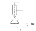
図1に示すようにTIG溶接において、アーク1を発生させるタングステン電極2の形状は40°前後の円錐形状である。
【0014】
しかし、この形状でタングステン電極2をタングステン電極の中心軸4で回転させるとアーク1は同じ位置にとどまる。即ち図1に示す溶融金属池3の位置にとどまるものである。
【0015】
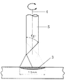
そこで、狭開先溶接で両側金属材の間隔が6〜12mm程度と狭い溶接を行うためには両側金属壁を溶融させる必要がありアーク1を直接側壁に当てることが望まれる。
この問題を解決するために、図2に示すようにタングステン電極2を30°〜40°の角度で研磨し、溶接線に対して、90°の位置に先端を配置して溶接を行うとタングステン電極の中心軸4から8mm外側まで溶込みを得ることが出来る。
【0016】
本発明において、図2に示すように30°〜40°の角度で研磨したタングステン電極のことを偏芯形状の電極5という。
【0017】
図3A、図3Bは本発明における偏芯形状の電極の溶込み巾を示す図であり、図3Aは45°の角度で研磨した偏芯形状の電極において±90°、即ち180°回転反復させると16mm巾の溶込みを得ることが出来ることを示しており、図3Bは30°の角度で研磨した偏芯形状の電極において±90°、即ち180°回転反復させると14mm巾の溶込みを得ることが出来ることを示している。
【0018】
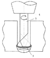
図4に示すように、この方式を利用開先巾8mmの狭開先の中で同じ180°回転反復ウィービングを行うと金属の両側側壁6,6’にアーク1を当てることができ十分なる溶込みを得ることができる。
【0019】
図5は偏芯形状の電極の回転によるウィービングの軌跡を示す図であり、この図5に示すように回転角度を変えることで円弧ウィービング巾の調整を行うこととなり開先巾及び溶接速度に応じて±45°(ウイービング巾90°)から±90°(ウイービング巾180°)にすることが有効である。
【0020】
図6A、図6Bは図5をさらに分かりやすく説明した図であり、図6Aは開先巾が狭い場合(6〜10mm)は±45°(ウイービング巾90°)にすることを示し、図6Bは開先巾が広い場合(12〜14mm)は±90°(ウイービング巾180°)にすることを示している。
【0021】
当然開先内をうめるために溶接ワイヤを供給することが必要であるが高速走行溶接を行うと金属溶融池が長くなり溶接金属冷却が遅れ表面外観がみだれる。そこで、これを補うため、図7に示すように進行方向後部から溶融池を冷却させるため前方のワイヤとは別の冷却ワイヤ8を挿入する方法を採用することで解決することができる。加えて、この冷却ワイヤ8を溶かして溶融金属を冷却させて高速走行溶接を行うだけでなく溶接金属の継手性能を改善することが可能である。
生産性を大幅に改善するために前方から供給されるワイヤ7を加熱することで溶着速度を大幅に改善することが可能である。
加えて両方からワイヤを供給するため溶接方向に関して往復で溶接が可能であり、従来の戻し時間を必要とせず、生産効率を大幅に改善することができる。そこで前後から送球されるワイヤ7,8はいずれも加熱して供給し溶着速度を向上させる方法も採用し生産性を向上させるものである。
【0022】
本発明では偏芯形状の電極5を回転反復して溶接するが両側で停止させることで両側の金属壁6,6’を溶融させるので溶込みを確保することは問題ないが円弧回転移動中の中央部に溶融金属用ワイヤ7が供給され溶着金属となる。この時溶融金属池3はワイヤ7を溶かすことで冷却され溶融金属池3の深さは浅くなり溶着速度を向上させることが難しい。そこで回転ウィービング両端部で停止している時に流す溶接電流と反復ウィービング移動中の場合は図8に示すような異なった溶接電流を流すことが要求される。
反復ウィービング中により高い電流を流し両端部停止中は若干低い電流を流すことが望まれる。即ち、両側停止時は側壁6,6’に直接アーク1が当たることで金属側壁6,6’を容易に溶かすことが出来るため低エネルギで充分である。
【0023】
ワイヤ供給量も電流と同じ傾向にあり円弧回転と同期して図7のように制御することが必要である。即ち、高い電流で溶融金属池3を十分溶かしておいて、金属の両側壁6,6’にアーク1が向いたときワイヤー7が十分に溶けるようにするものである。
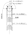
図9に示すように、従来、狭開先溶接で板厚が厚い初期層の溶接を行う場合大気中から溶融金属を保護するため不活性ガス雰囲気にする必要があり、金属開先表面から多量(80〜100L/分)の不活性ガス(アルゴン又はヘリウム)を流す方法が採用されている。しかし、不活性ガスは大変高価であり溶接コストを上げる要因になっている。
【0024】
この問題を解決するために図10に示す構造のTIGトーチを採用することで解決した。
即ち、狭開先TIG溶接装置において、偏芯形状の電極5を保持するTIGトーチ9が偏芯形状の電極外径に対し同心円の内径が+1.0〜1.8mm(図中A)大きく、かつ当該外径は18°〜22°、最も好適には20°(図中・1)の円錐形状のガスノズルを有し、さらにその外径側にもうひとつのガスノズル11を持ち、その内側の円錐角度が12°〜16°、最も好適には14°(図中・2)であるTIGトーチ先端形状を有し、それぞれの空隙に流量の異なる不溶性ガスを流すことからなる構造である。
円錐形状のガスノズル10にはセンターガスが流れ、もうひとつのガスノズル11にはシールドガスが流れるようになっている。
【0025】
円錐形状のガスノズル10に流量5L/分、センターガスを流し、外側のガスノズル11に15L/分、シールドガスを流すと、円錐形状のガスノズル10の外側円錐角度・1ともうひとつのガスノズル11内面角度・2の組合せによってシールドガス(アルゴン)の吸引効果が発生し、狭開先溶接による厚板溶接の初期層部分の雰囲気酸素濃度を30PPM以下にすることが図10に示す測定結果から明確である。即ち、円錐形状のガスノズル10の巾が狭くなっているのでセンターガスの量が少なくても流速が早く、そのためシールドガスがセンターガスの流速に引っ張られてシールドガスが内側に引き込まれる(入ってくる)ということである。
この結果、従来80〜100L/分供給していた不活性ガスを1/5〜1/6に削減することができコストダウンへの効果は甚大である。
【0026】
【発明の効果】
本発明は以上の構成を有するので、狭開先TIG溶接において生産能力を高め、生産コストを下げることが出来るものである。
【図面の簡単な説明】
【図1】従来のTIG溶接の電極を示す図である。
【図2】本発明の偏芯形状の電極を示す図である。
【図3A】本発明の45°の角度で研磨した偏芯形状の電極の溶込み巾を示す図である。
【図3B】本発明の30°の角度で研磨した偏芯形状の電極の溶込み巾を示す図である。
【図4】本発明の狭開先内での偏芯形状の電極の回転を示す図である。
【図5】本発明の偏芯形状の電極の回転によるウィービングの軌跡を示す図である。
【図6A】本発明の開先巾が狭い場合を示す図である。
【図6B】本発明の開先巾が広い場合を示す図である。
【図7】本発明の冷却ワイヤを送入することを示す図である。
【図8】本発明の偏芯形状の電極の回転溶接制御システムを示す図である。
【図9】従来の狭開先溶接におけるガスシールドを示す図である。
【図10】本発明の狭開先溶接における2つの種類のガスシールドを示す図である。
【図11】本発明の酸素濃度測定値を示す図である。
【符号の説明】
1 アーク
2 タングステン電極
3 溶融金属池
4 中心軸
5 偏芯形状の電極
6,6’ 金属壁
7 前方からのワイヤ
8 後方からのワイヤ
9 TIGトーチ
10 円錐形状のガスノズル
11 もうひとつのガスノズル[0001]
TECHNICAL FIELD OF THE INVENTION
The present invention relates to a non-consumable arc welding (TIG welding) pipe made of various metal materials and a narrow groove TIG welding apparatus for large structures.
[0002]
[Prior art]
In narrow groove welding performed using a conventionally proposed non-consumable arc (TIG welding) welding method, there is a method in which a conical electrode is bent and the electrode is rotated (for example,
[0003]
[Patent Document 1]
Patent Publication 7-276051 (Detailed Description of the Invention [0006])
[Patent Document 2]
Patent publication Hei 10-6011 (Detailed description of the invention [0006])
[Patent Document 3]
Patent Publication No. 7-108379 (Detailed description of the invention [0005])
[0004]
[Problems to be solved by the invention]
However, the prior art has a problem in the production capacity, the problem is that the thicker the plate, the larger the consumption of the inert gas and the higher the production cost, and furthermore, the direction of supply of the wire is fixed. Therefore, there is a problem that the productivity is reduced by the time required to return the welding head in the longitudinal welding due to the determination of the welding direction.
[0005]
Therefore, an object of the present invention is to provide a narrow groove TIG welding device that can increase production capacity and reduce production cost.
[0006]
[Means to solve the problem]
In order to achieve the above object, a narrow groove TIG welding device of the present invention comprises:
In a narrow groove TIG welding apparatus for joining and welding a metal having a narrow groove, the electrode is not a conical electrode but an eccentric electrode, and the eccentric electrode is rotated within the narrow groove. Melting the wire.
[0007]
In the narrow groove TIG welding apparatus, it is preferable that a wire is fed from the front and the rear of the eccentric electrode.
[0008]
It is preferable that, of the two wires, the wire fed from the front of the eccentric electrode is heated, and the wire sent from the rear is fed without preheating.
[0009]
In the two wires, it is preferable that both the wire fed from the front and the wire sent from the back of the eccentric electrode are heated and fed.
[0010]
In the narrow groove TIG welding device, the rotation angle of the eccentric electrode may be ± 45 ° to ± 90 ° depending on the combination of the width of the narrow groove and the size of the eccentric electrode. It is suitable.
[0011]
Further, in the narrow groove TIG welding apparatus, when rotating the eccentric electrode to the left and right, at both ends of the metal side wall, a current flowing simultaneously with stopping and a current flowing when moving in the opposite direction are different currents. Is preferred.
[0012]
Further, in the narrow groove TIG welding apparatus, the TIG torch holding the eccentric electrode has an inner diameter of the concentric circle larger by +1.0 to 1.8 mm than the outer diameter of the eccentric electrode, and the outer diameter is 18 A TIG torch tip shape having a conical nozzle of about 22 ° and another gas nozzle on its outer diameter side and a conical angle of 12 ° to 16 ° on its inner side, and each gap It is preferable to flow an inert gas having a different flow rate into the air.
[0013]
BEST MODE FOR CARRYING OUT THE INVENTION
Hereinafter, an example of an embodiment of the present invention will be described with reference to the drawings.
As shown in FIG. 1, in TIG welding, the shape of the tungsten electrode 2 for generating the
[0014]
However, when the tungsten electrode 2 is rotated around the
[0015]
Therefore, in order to perform narrow welding in which the distance between the metal materials on both sides is narrow by about 6 to 12 mm by narrow groove welding, it is necessary to melt the metal walls on both sides, and it is desired to directly apply the
In order to solve this problem, the tungsten electrode 2 is polished at an angle of 30 ° to 40 ° as shown in FIG. Penetration can be obtained from the
[0016]
In the present invention, a tungsten electrode polished at an angle of 30 ° to 40 ° as shown in FIG. 2 is referred to as an
[0017]
3A and 3B are views showing the penetration width of the eccentric electrode in the present invention, and FIG. 3A shows the eccentric electrode polished at an angle of 45 ° repeated ± 90 °, that is, rotated 180 °. FIG. 3B shows that an eccentric electrode polished at a 30 ° angle can be penetrated by ± 90 °, that is, 180 °, to form a 14mm wide penetration. It shows that it can be obtained.
[0018]
As shown in FIG. 4, when the same 180 ° rotation repeated weaving is performed in a narrow groove having a groove width of 8 mm using this method, the
[0019]
FIG. 5 is a diagram showing the locus of weaving due to the rotation of the eccentric electrode. As shown in FIG. 5, the arc weaving width is adjusted by changing the rotation angle, and according to the groove width and the welding speed. It is effective to change from ± 45 ° (weaving width 90 °) to ± 90 ° (weaving width 180 °).
[0020]
FIGS. 6A and 6B are diagrams illustrating FIG. 5 more clearly. FIG. 6A shows that when the groove width is narrow (6 to 10 mm), ± 45 ° (weaving width 90 °) is used. Indicates that when the groove width is wide (12 to 14 mm), it is ± 90 ° (weaving width 180 °).
[0021]
Naturally, it is necessary to supply a welding wire to fill the groove. However, when high-speed traveling welding is performed, the molten metal pool becomes long, the cooling of the weld metal is delayed, and the surface appearance can be seen. In order to compensate for this, the problem can be solved by adopting a method of inserting a cooling wire 8 different from the front wire in order to cool the molten pool from the rear in the traveling direction as shown in FIG. In addition, it is possible not only to perform high-speed traveling welding by melting the cooling wire 8 to cool the molten metal, but also to improve the joint performance of the weld metal.
By heating the
In addition, since the wires are supplied from both sides, the welding can be performed reciprocally in the welding direction, and the conventional return time is not required, and the production efficiency can be greatly improved. Therefore, the
[0022]
In the present invention, the
It is desirable to have a higher current flow during repetitive weaving and a slightly lower current flow during both end stops. That is, when the
[0023]
The wire supply amount also tends to be the same as the current, and needs to be controlled as shown in FIG. 7 in synchronization with the arc rotation. That is, the
As shown in FIG. 9, conventionally, when welding an initial layer having a large plate thickness by narrow groove welding, it is necessary to use an inert gas atmosphere to protect the molten metal from the atmosphere, and a large amount of (80 to 100 L / min) of an inert gas (argon or helium) is flowed. However, the inert gas is very expensive and raises the welding cost.
[0024]
In order to solve this problem, a TIG torch having a structure shown in FIG. 10 was adopted.
That is, in the narrow groove TIG welding device, the
The center gas flows through the
[0025]
When the center gas is flowed at a flow rate of 5 L / min through the
As a result, the amount of the inert gas conventionally supplied at 80 to 100 L / min can be reduced to 1/5 to 1/6, and the effect on cost reduction is enormous.
[0026]
【The invention's effect】
Since the present invention has the above configuration, it is possible to increase production capacity and reduce production cost in narrow groove TIG welding.
[Brief description of the drawings]
FIG. 1 is a view showing a conventional TIG welding electrode.
FIG. 2 is a view showing an eccentric electrode according to the present invention.
FIG. 3A is a diagram showing the penetration width of an eccentric electrode polished at an angle of 45 ° according to the present invention.
FIG. 3B is a diagram showing the penetration width of an eccentric electrode polished at an angle of 30 ° according to the present invention.
FIG. 4 is a view showing rotation of an eccentric electrode in a narrow groove according to the present invention.
FIG. 5 is a diagram showing a locus of weaving due to rotation of an eccentric electrode of the present invention.
FIG. 6A is a view showing a case where a groove width of the present invention is narrow.
FIG. 6B is a diagram showing a case where the groove width of the present invention is wide.
FIG. 7 is a diagram showing the feeding of the cooling wire of the present invention.
FIG. 8 is a view showing a rotary welding control system for an eccentric electrode according to the present invention.
FIG. 9 is a view showing a gas shield in conventional narrow groove welding.
FIG. 10 is a view showing two types of gas shields in narrow groove welding according to the present invention.
FIG. 11 is a diagram showing measured values of oxygen concentration according to the present invention.
[Explanation of symbols]
DESCRIPTION OF
Claims (7)
Priority Applications (1)
| Application Number | Priority Date | Filing Date | Title |
|---|---|---|---|
| JP2003029903A JP2004237326A (en) | 2003-02-06 | 2003-02-06 | Narrow weld joint tungsten inert gas (tig) welding machine |
Applications Claiming Priority (1)
| Application Number | Priority Date | Filing Date | Title |
|---|---|---|---|
| JP2003029903A JP2004237326A (en) | 2003-02-06 | 2003-02-06 | Narrow weld joint tungsten inert gas (tig) welding machine |
Related Child Applications (1)
| Application Number | Title | Priority Date | Filing Date |
|---|---|---|---|
| JP2007008672U Continuation JP3139345U (en) | 2007-11-09 | 2007-11-09 | Narrow groove TIG welding equipment |
Publications (2)
| Publication Number | Publication Date |
|---|---|
| JP2004237326A true JP2004237326A (en) | 2004-08-26 |
| JP2004237326A5 JP2004237326A5 (en) | 2005-06-30 |
Family
ID=32956950
Family Applications (1)
| Application Number | Title | Priority Date | Filing Date |
|---|---|---|---|
| JP2003029903A Pending JP2004237326A (en) | 2003-02-06 | 2003-02-06 | Narrow weld joint tungsten inert gas (tig) welding machine |
Country Status (1)
| Country | Link |
|---|---|
| JP (1) | JP2004237326A (en) |
Cited By (10)
| Publication number | Priority date | Publication date | Assignee | Title |
|---|---|---|---|---|
| JP2013035043A (en) * | 2011-08-09 | 2013-02-21 | Mitsubishi Heavy Ind Ltd | Welding method and welding apparatus |
| CN103415369A (en) * | 2011-03-07 | 2013-11-27 | 株式会社神户制钢所 | Dissimilar metal joining method |
| WO2014155180A3 (en) * | 2013-03-25 | 2014-12-11 | Lincoln Global, Inc. | Methods of and system for laser cladding with multiple heated consumables |
| US9085041B2 (en) | 2009-01-13 | 2015-07-21 | Lincoln Global, Inc. | Method and system to start and use combination filler wire feed and high intensity energy source for welding |
| KR101615918B1 (en) * | 2015-04-07 | 2016-04-27 | 두산중공업 주식회사 | The welding method with double-head |
| US10086461B2 (en) | 2009-01-13 | 2018-10-02 | Lincoln Global, Inc. | Method and system to start and use combination filler wire feed and high intensity energy source for welding |
| CN108907414A (en) * | 2018-09-28 | 2018-11-30 | 山东大学 | A kind of double tungsten electrode TIG narrow gap welding methods of the high speed of welding of high deposition efficiency |
| US10464168B2 (en) | 2014-01-24 | 2019-11-05 | Lincoln Global, Inc. | Method and system for additive manufacturing using high energy source and hot-wire |
| US11027362B2 (en) | 2017-12-19 | 2021-06-08 | Lincoln Global, Inc. | Systems and methods providing location feedback for additive manufacturing |
| CN119634902A (en) * | 2024-12-09 | 2025-03-18 | 西安航天动力机械有限公司 | A hot wire TIG+submerged arc hybrid welding method for high-strength steel conical workpiece |
-
2003
- 2003-02-06 JP JP2003029903A patent/JP2004237326A/en active Pending
Cited By (15)
| Publication number | Priority date | Publication date | Assignee | Title |
|---|---|---|---|---|
| US9085041B2 (en) | 2009-01-13 | 2015-07-21 | Lincoln Global, Inc. | Method and system to start and use combination filler wire feed and high intensity energy source for welding |
| US10086461B2 (en) | 2009-01-13 | 2018-10-02 | Lincoln Global, Inc. | Method and system to start and use combination filler wire feed and high intensity energy source for welding |
| US9782850B2 (en) | 2009-01-13 | 2017-10-10 | Lincoln Global, Inc. | Method and system to start and use combination filler wire feed and high intensity energy source for welding |
| US20130341306A1 (en) * | 2011-03-07 | 2013-12-26 | Kabushiki Kaisha Kobe Seiko Sho (Kobe Steel, Ltd.) | Method for bonding dissimilar metals to each other |
| CN103415369B (en) * | 2011-03-07 | 2015-11-25 | 株式会社神户制钢所 | Dissimilar metal joining method |
| US9339887B2 (en) | 2011-03-07 | 2016-05-17 | Kobe Steel, Ltd. | Method for bonding dissimilar metals to each other |
| DE112012001128T5 (en) | 2011-03-07 | 2013-12-24 | Kabushiki Kaisha Kobe Seiko Sho (Kobe Steel, Ltd.) | Method for connecting different metals |
| CN103415369A (en) * | 2011-03-07 | 2013-11-27 | 株式会社神户制钢所 | Dissimilar metal joining method |
| JP2013035043A (en) * | 2011-08-09 | 2013-02-21 | Mitsubishi Heavy Ind Ltd | Welding method and welding apparatus |
| WO2014155180A3 (en) * | 2013-03-25 | 2014-12-11 | Lincoln Global, Inc. | Methods of and system for laser cladding with multiple heated consumables |
| US10464168B2 (en) | 2014-01-24 | 2019-11-05 | Lincoln Global, Inc. | Method and system for additive manufacturing using high energy source and hot-wire |
| KR101615918B1 (en) * | 2015-04-07 | 2016-04-27 | 두산중공업 주식회사 | The welding method with double-head |
| US11027362B2 (en) | 2017-12-19 | 2021-06-08 | Lincoln Global, Inc. | Systems and methods providing location feedback for additive manufacturing |
| CN108907414A (en) * | 2018-09-28 | 2018-11-30 | 山东大学 | A kind of double tungsten electrode TIG narrow gap welding methods of the high speed of welding of high deposition efficiency |
| CN119634902A (en) * | 2024-12-09 | 2025-03-18 | 西安航天动力机械有限公司 | A hot wire TIG+submerged arc hybrid welding method for high-strength steel conical workpiece |
Similar Documents
| Publication | Publication Date | Title |
|---|---|---|
| US4254322A (en) | Narrow weld-groove welding process and apparatus therefor | |
| US9718147B2 (en) | Method and system to start and use combination filler wire feed and high intensity energy source for root pass welding of the inner diameter of clad pipe | |
| US9782850B2 (en) | Method and system to start and use combination filler wire feed and high intensity energy source for welding | |
| JP3934251B2 (en) | TIG welding method and apparatus | |
| CA2505731C (en) | Mig-plasma welding | |
| EP3126083B1 (en) | Method and system to use ac welding waveform and enhanced consumable to improve welding of galvanized workpiece | |
| EP2744619B1 (en) | Method to start and use combination filler wire feed and high intensity energy source for welding | |
| US2756311A (en) | High-speed tandem arc working | |
| US4136273A (en) | Method and apparatus for tig welding | |
| KR102134045B1 (en) | Adaptable rotating arc welding method and system | |
| US20130327749A1 (en) | Method and system to start and use combination filler wire feed and high intensity energy source for welding aluminum to steel | |
| CN103737158B (en) | A kind of electric arc welding gun with double consumable electrodes and a welding method thereof controlled based on heat input | |
| US20130092667A1 (en) | Method and System to Start and Use Combination Filler Wire Feed and High Intensity Energy Source for Welding | |
| JP2013534185A (en) | Arc welding apparatus and method using MIG / MAG torch in combination with TIG torch | |
| CN108971806A (en) | A kind of adjustable electric arc increasing material device and method of feed direction | |
| JP2015501727A (en) | DC electrode minus rotary arc welding method and system | |
| JP2009545449A (en) | TIG blaze welding using metal transfer in droplets at a controlled frequency | |
| WO2014087227A1 (en) | Method and system to start and use combination filler wire feed and high intensity energy source for welding | |
| JP2004237326A (en) | Narrow weld joint tungsten inert gas (tig) welding machine | |
| CN104785931A (en) | Plasma-submerged arc hybrid welding system and welding method thereof | |
| CN113941763A (en) | Shaking/rotating arc consumable electrode welding method adopting coarse welding wire | |
| JPS6072678A (en) | High-speed arc welding method | |
| CA1307563C (en) | Downward gas-metal-arc welding process | |
| JP3117287B2 (en) | Consumable electrode arc welding method | |
| JP3139345U (en) | Narrow groove TIG welding equipment |
Legal Events
| Date | Code | Title | Description |
|---|---|---|---|
| A521 | Written amendment |
Free format text: JAPANESE INTERMEDIATE CODE: A523 Effective date: 20041019 |
|
| A621 | Written request for application examination |
Free format text: JAPANESE INTERMEDIATE CODE: A621 Effective date: 20060117 |
|
| A977 | Report on retrieval |
Free format text: JAPANESE INTERMEDIATE CODE: A971007 Effective date: 20070906 |
|
| A131 | Notification of reasons for refusal |
Effective date: 20070918 Free format text: JAPANESE INTERMEDIATE CODE: A131 |
|
| A521 | Written amendment |
Free format text: JAPANESE INTERMEDIATE CODE: A523 Effective date: 20071107 |