JP2004257529A - Mechanical seal device - Google Patents
Mechanical seal device Download PDFInfo
- Publication number
- JP2004257529A JP2004257529A JP2003051577A JP2003051577A JP2004257529A JP 2004257529 A JP2004257529 A JP 2004257529A JP 2003051577 A JP2003051577 A JP 2003051577A JP 2003051577 A JP2003051577 A JP 2003051577A JP 2004257529 A JP2004257529 A JP 2004257529A
- Authority
- JP
- Japan
- Prior art keywords
- mechanical seal
- seal
- liquid
- housing
- pump
- Prior art date
- Legal status (The legal status is an assumption and is not a legal conclusion. Google has not performed a legal analysis and makes no representation as to the accuracy of the status listed.)
- Pending
Links
Images

Landscapes
- Mechanical Sealing (AREA)
Abstract
【課題】簡単な構造により、ポンプ揚液の漏洩を防止するとともに、万一、ポンプ揚液が漏洩しその漏液が腐食性のものやスラリー分のあるものであったとしても、軸受装置などの腐食損傷を確実に防止することができるメカニカルシール装置を提供する。
【解決手段】回転軸1は、ポンプケーシング2の後側に設けたシールハウジング32に収容されているダブル形のメカニカルシール13によって回転自在に軸封し、シールハウジング32を装入したハウジング装入室33を介して、軸受装置34を構成しているベアリングボックス4の軸受30A,30B,30Cによって回転自在に支持する。また、ベアリングボックス4の外部にアキュムレータによってなる蓄圧タンク37を設置し、この蓄圧タンク37から潤滑・軸封液供給管38を介してシールハウジング32に潤滑・軸封液を供給する。
【選択図】 図1A simple structure prevents leakage of pump liquid, and even if the pump liquid leaks and the leak liquid is corrosive or has a slurry content, a bearing device, etc. Provided is a mechanical seal device capable of surely preventing corrosion damage of a member.
A rotary shaft is rotatably sealed by a double-type mechanical seal housed in a seal housing provided on a rear side of a pump casing, and the housing is loaded with the seal housing. It is rotatably supported by the bearings 30A, 30B, 30C of the bearing box 4 constituting the bearing device 34 via the chamber 33. Further, a pressure accumulating tank 37 formed of an accumulator is installed outside the bearing box 4, and the lubricating / shaft sealing liquid is supplied from the accumulating tank 37 to the seal housing 32 via the lubricating / shaft sealing liquid supply pipe 38.
[Selection diagram] Fig. 1
Description
【0001】
【発明の属する技術分野】
本発明は、メカニカルシール装置に関する。
【0002】
【従来の技術】
従来より、たとえば、ポンプの回転主軸を軸封するメカニカルシールにおける摺動部の冷却を行う標準的な手法として、フラッシング水を外部の水源より導いて封水する手法と、ポンプの自揚水をフラッシング水として封水する手法が知られている。ところが、前者のフラッシング水を外部の水源より導いて封水する手法は、導水設備費用が高くなるばかりか、保全のためのメンテナンスが煩雑になるなどの難点を有している。また、後者の自揚水をフラッシング水として封水する手法は、ポンプの自揚水にスラリー分がある場合には、ポンプ軸受にダメージを与えて、ポンプの運転継続を不能にする難点を有している。
【0003】
そこで、前者および後者のようなフラッシング水の使用を避けて、ポンプ軸受の潤滑油をメカニカルシールの潤滑油として共用できるように構成したメカニカルシール装置が提案されている。
【0004】
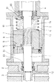
まず、図3に示すように、ポンプの回転軸1の先端部にポンプケーシング2内に収納したインペラ(羽根車)3を取付け、ポンプケーシング2とベアリングボックス4との間にシリンダーの機能を有する外套筒5を設置して流体収納部6を構成し、回転軸1のポンプケーシング2とベアリングボックス4の間の略中央部にネジポンプによってなる流体加圧装置7を形成し、流体加圧装置7のケースの働きをするピストン8の外周面を外套筒5の内周面に摺動可能かつ液密に接触させ、ピストン8内に逆止弁9を含む圧力流体通路10を形成し、また圧力調整のために外套筒5の内周面に圧力調整溝11を設け、インペラ3の取付け位置直後の回転軸1とポンプケーシング2の後壁の貫通孔12とにメカニカルシール13を設置し、メカニカルシール13とピストン8の前面およびシリンダー5の内面とで囲まれた空間を高圧流体室14となし、ベアリングボックス4の前面とピストン8の後面との間に加圧スプリング15を介在させ、ベアリングボックス4の前面とピストン8の後面およびシリンダー5の内面によって囲まれた空間を流体収納部6とし、この流体収納部6には、メカニカルシール13の摺動面を潤滑するとともに、その粘性で摺動面よりの漏液を防ぎ、かつ冷却作用を発揮できる潤滑・軸封液(潤滑油)を充満してなるメカニカルシール装置がある(たとえば、特許文献1参照。)。
【0005】
一方、図4に示すように、回転軸1のベアリングボックス4内に位置する部分にネジポンプによってなる流体加圧装置7を設け、この流体加圧装置7と対応して作動するピストン8の内周面は、前記流体加圧装置7の外周面と適宜の間隔をおき、かつその外周面を外套筒5として機能するベアリングボックス4の内周面に摺動可能かつ液密に接触させ、ピストン8の後部に加圧スプリング15を設けてピストン8に付勢し、ピストン8の後側を低圧室17、前側を高圧室18となし、外套筒5の内周面のピストン8の前進停止位置に対応する位置に当たり部19を設け、外套筒5の外部に設置されたタンク20と外套筒5との間に2個の連通路21,22を設け、その1つを低圧室17に、他の1つはピストン8が位置する場所に連通させるとともに、ピストン8が高圧流体によって押圧されたとき、ピストン8の外周部に設けた流体通路23、調圧溝24および外套筒5に設けた流体逃がし溝25より移送された流体が、前記連通路22よりタンク20内に移送されるようになし、前記外套筒5として機能するベアリングボックス4の前壁26に貫通孔27A,27Bを穿設し、ピストン8の前部に設けた逆止弁28を有する流体通路29の開口部と合致する位置に前記貫通孔27Aを位置させ、前記タンク20、低圧室17および高圧室18に、メカニカルシール13の潤滑・軸封液(潤滑油)を充満させたメカニカルシール装置がある(たとえば、特許文献2参照。)。
【0006】
前記図3および図4で説明した従来のメカニカルシール装置では、軸受30,30A,30B,30Cのための潤滑油を回転軸1とインペラ(羽根車)3の回転時、つまりポンプなどの被軸封機器の運転時には、ネジポンプによってなる流体加圧装置7の加圧でメカニカルシール13に供給し続け、回転軸1が停止しているポンプなどの被軸封機器の運転停止時には、加圧スプリング15のばね力によって、ピストン8を介してメカニカルシール13に与えている。
【0007】
【特許文献1】
特開昭58−113660号公報、第2図
【特許文献2】
特開昭59−119098号公報、実施例断面図
【0008】
【発明が解決しようとする課題】
【0009】
ところで、通常は、ポンプ揚液の圧力よりも潤滑油の圧力の方が高いために、メカニカルシール13では潤滑油がポンプ側に洩れてポンプ揚液に混入する。ところが、ポンプ側へのもれによって潤滑油が不足して、潤滑油の圧力が低下したり、ポンプの締切運転時などにおいてポンプ揚液の圧力が高くなると、ポンプ揚液が潤滑油側に流れて、潤滑油にポンプ揚液が混入したり、あるいは、メカニカルシール13の摺動部の面荒れが進むことなどによって、潤滑油にポンプ揚液が混入することもある。このように、潤滑油にポンプ揚液が混入したとしても、非腐食性のポンプ揚液や、スラリー分のないポンプ揚液であれば、さほど大きな問題が生じることはない。しかし、腐食性のポンプ揚液が潤滑油に混入すると、耐食材料で構成されていない回転軸1や軸受30,30A,30B,30Cなどが損傷を受ける重大な問題につながり、スラリー分のあるポンプ揚液が潤滑油に混入すると、軸受30,30A,30B,30Cなどにダメージを与えて、ポンプの運転継続を不能にする重大な問題につながる。しかも、ネジポンプによってなる流体加圧装置7、加圧スプリング15、逆止弁9を含む圧力流体通路10、逆止弁28を有する流体通路29などが必要であるので、構造が複雑である難点を有している。
【0010】
本発明は、このような事情を考慮してなされたものであって、簡単な構造により、ポンプ揚液の漏洩を防止するとともに、万一、ポンプ揚液が漏洩しその漏液が腐食性のものやスラリー分のあるものであったとしても、軸受装置などの腐食損傷を確実に防止することができるメカニカルシール装置を提供することを目的としている。
【0011】
【課題を解決するための手段】
前記目的を達成するために、本発明に係るメカニカルシール装置は、被軸封機器の回転軸を軸封するメカニカルシールと、このメカニカルシールを装入したシールハウジングと、このシールハウジングに潤滑・軸封液を供給する蓄圧タンクとを備え、前記回転軸は前記シールハウジングが装入されているハウジング装入室を介して軸受装置によって回転自在に支持されていることを特徴としている。
【0012】
本発明によれば、メカニカルシールが装入されているシールハウジングに対して、蓄圧タンクにより揚液の圧力に応じた圧力で潤滑・軸封液(潤滑油)を供給して軸封することができる。また、万一、揚液がシールハウジングから洩れたとしても、洩れた揚液はハウジング装入室で受け止められるので軸受装置に影響がおよばない。したがって、たとえ腐食性の揚液やスラリー分のある揚液が洩れても、軸受装置などの腐食損傷を確実に防止することができる。
【0013】
【発明の実施の形態】
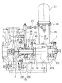
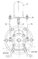
以下、本発明の好適な実施の形態を図面に基づいて説明する。図1は、本発明の一実施の形態を示す縦断面図、図2は図1の右側面図である。なお、図3,図4の従来例と同一もしくは相当部分には、同一符号を付して説明する。
図1および図2において、ポンプの回転軸1の先端部にポンプケーシング2内に収納したインペラ(羽根車)3を取付け、回転軸1は、ポンプケーシング2の後側に設けたシールハウジング32に収容されているメカニカルシール13によって回転自在に軸封されており、このメカニカルシール13は、ポンプケーシング側の前段のメカニカルシール13Aと、ベアリングボックス4側の後段のメカニカルシール13Bとを備えた2箇所の摺動部を有するダブル形のメカニカルシール13によって構成されている。また、シールハウジング32を装入したハウジング装入室33を介して、軸受装置34を構成しているベアリングボックス4の軸受30A,30B,30Cによって回転自在に支持されている。
【0014】
ベアリングボックス4の外部には、支持棒35,35と支持板36とを介して、たとえばアキュムレータによってなる蓄圧タンク37が設置されており、この蓄圧タンク37から潤滑・軸封液供給管38を介してシールハウジング32に潤滑・軸封液を供給し、メカニカルシール13における前段のメカニカルシール13Aと後段のメカニカルシール13Bの摺動面を潤滑し、粘性で摺動面よりの漏液を防ぎ、かつ冷却作用を発揮できるように構成してある。また、ハウジング装入室33の底部には、排液孔39が設けられ、ベアリングボックス4には、軸受30A,30B,30C潤滑用の潤滑油を注油する注油孔40Aと排油孔40Bを設けてある。なお、図中41はバルブを示し、潤滑・軸封液供給管38に介設してある。また、42はVリングを示し、ベアリングボックス4の前端に取り付けたシール押えで被冠されて、ベアリングボックス4内を循環する潤滑油がハウジング装入室33に漏洩するのを防止している。
【0015】
このような構成であれば、メカニカルシール13が装入されているシールハウジング32に対して、たとえばアキュムレータによってなる蓄圧タンク37により潤滑・軸封液(潤滑油)を供給して軸封することができる。しかも、万一、揚液がシールハウジング32から漏洩したとしても、漏洩した揚液は、シールハウジング32が装入されているハウジング装入室33で受け止められたのち、その底部に設けられている排液孔39から排出して適宜回収することが可能であるため、軸受装置34の軸受30A,30B,30Cに影響がおよぶことはない。したがって、たとえ腐食性の揚液が洩れても、耐食材料で構成されていない回転軸1や軸受30,30A,30B,30Cなどが損傷を受けることはない。また、スラリー分のある揚液が洩れても、軸受30,30A,30B,30Cがダメージを受けることはないので、ポンプの適性運転を継続することができる。しかも、図3および図4で説明した従来例で必要とされるネジポンプによってなる流体加圧装置7、加圧スプリング15、逆止弁9を含む圧力流体通路10、逆止弁28を有する流体通路29などを全て省略して、構造を大幅に簡単にすることができる。
【0016】
【発明の効果】
以上説明したように、本発明に係るメカニカルシール装置は構成されているので、以下のような格別の効果を奏する。
【0017】
すなわち、メカニカルシールが装入されているシールハウジングに対して、蓄圧タンクにより潤滑・軸封液を供給して軸封することができる。しかも、万一、揚液がシールハウジングから漏洩したとしても、漏洩した揚液は、シールハウジングが装入されているハウジング装入室で受け止めることができるので、軸受装置に影響がおよぶことはない。したがって、腐食性の揚液が洩れても、耐食材料で構成されていない回転軸や軸受装置などが損傷を受けることはない。また、スラリー分のある揚液が洩れても、軸受装置がダメージを受けることはないので、ポンプの適性運転を継続することができる。
【図面の簡単な説明】
【図1】本発明の一実施の形態を示す縦断面図である。
【図2】図1の右側面図である。
【図3】第1従来例の縦断面図である。
【図4】第2従来例の縦断面図である。
【符号の説明】
1 回転軸
13 メカニカルシール
32 シールハウジング
33 ハウジング装入室
34 軸受装置
37 蓄圧タンク[0001]
TECHNICAL FIELD OF THE INVENTION
The present invention relates to a mechanical seal device.
[0002]
[Prior art]
Conventionally, for example, as a standard method of cooling a sliding portion in a mechanical seal for sealing a rotary main shaft of a pump, a method of guiding flushing water from an external water source to seal the water, and a method of flushing self-pumping water of the pump. A technique for sealing water as water is known. However, the former method of guiding the flushing water from an external water source and sealing the water has disadvantages such as not only increasing the cost of water introduction equipment but also complicating maintenance for maintenance. Also, the latter method of sealing the self-pumping water as flushing water has a drawback that if the pump's self-pumping water has a slurry component, it damages the pump bearing and makes it impossible to continue the operation of the pump. I have.
[0003]
Therefore, a mechanical seal device has been proposed in which the use of flushing water as in the former and the latter is avoided and the lubricating oil for the pump bearing can be shared as the lubricating oil for the mechanical seal.
[0004]
First, as shown in FIG. 3, an impeller (impeller) 3 housed in a
[0005]
On the other hand, as shown in FIG. 4, a fluid pressurizing
[0006]
In the conventional mechanical seal device described with reference to FIGS. 3 and 4, lubricating oil for the
[0007]
[Patent Document 1]
JP-A-58-113660, FIG. 2 [Patent Document 2]
JP-A-59-119098, sectional view of the embodiment
[Problems to be solved by the invention]
[0009]
Incidentally, since the pressure of the lubricating oil is usually higher than the pressure of the pumping liquid, the lubricating oil leaks to the pump side in the
[0010]
The present invention has been made in view of such circumstances, and with a simple structure, prevents leakage of the pump liquid, and in the unlikely event that the pump liquid leaks, the liquid is corrosive. It is an object of the present invention to provide a mechanical seal device capable of reliably preventing corrosion damage of a bearing device and the like even if the material has a slurry content.
[0011]
[Means for Solving the Problems]
In order to achieve the above object, a mechanical seal device according to the present invention includes a mechanical seal that seals a rotating shaft of a shaft-sealed device, a seal housing in which the mechanical seal is loaded, and a lubrication / shaft in the seal housing. A pressure storage tank for supplying a sealed liquid, wherein the rotating shaft is rotatably supported by a bearing device via a housing charging chamber in which the seal housing is mounted.
[0012]
According to the present invention, lubrication / shaft sealing liquid (lubricating oil) can be supplied to the seal housing, in which the mechanical seal is inserted, by the pressure accumulating tank at a pressure corresponding to the pressure of the pumping liquid to seal the shaft. it can. Also, even if the pumped liquid leaks from the seal housing, the leaked pumped liquid is received by the housing charging chamber, and thus does not affect the bearing device. Therefore, even if a corrosive pumping liquid or a pumping liquid containing a slurry leaks, it is possible to reliably prevent corrosion damage to the bearing device and the like.
[0013]
BEST MODE FOR CARRYING OUT THE INVENTION
Hereinafter, preferred embodiments of the present invention will be described with reference to the drawings. FIG. 1 is a longitudinal sectional view showing an embodiment of the present invention, and FIG. 2 is a right side view of FIG. The same or corresponding parts as those in the conventional example shown in FIGS. 3 and 4 are denoted by the same reference numerals and described.
1 and 2, an impeller (impeller) 3 housed in a
[0014]
A
[0015]
With such a configuration, lubrication / shaft sealing liquid (lubricating oil) can be supplied to the
[0016]
【The invention's effect】
As described above, since the mechanical seal device according to the present invention is configured, the following special effects can be obtained.
[0017]
That is, lubrication and shaft sealing liquid can be supplied from the pressure accumulating tank to the seal housing in which the mechanical seal is inserted to seal the shaft. Moreover, even if the pumping liquid leaks from the seal housing, the leaked pumping liquid can be received in the housing charging chamber in which the seal housing is mounted, so that the bearing device is not affected. . Therefore, even if the corrosive pumping liquid leaks, the rotating shaft and the bearing device which are not made of the corrosion resistant material are not damaged. Also, even if the pumping liquid containing the slurry leaks, the bearing device is not damaged, so that the proper operation of the pump can be continued.
[Brief description of the drawings]
FIG. 1 is a longitudinal sectional view showing an embodiment of the present invention.
FIG. 2 is a right side view of FIG.
FIG. 3 is a longitudinal sectional view of a first conventional example.
FIG. 4 is a longitudinal sectional view of a second conventional example.
[Explanation of symbols]
DESCRIPTION OF
Claims (1)
Priority Applications (1)
| Application Number | Priority Date | Filing Date | Title |
|---|---|---|---|
| JP2003051577A JP2004257529A (en) | 2003-02-27 | 2003-02-27 | Mechanical seal device |
Applications Claiming Priority (1)
| Application Number | Priority Date | Filing Date | Title |
|---|---|---|---|
| JP2003051577A JP2004257529A (en) | 2003-02-27 | 2003-02-27 | Mechanical seal device |
Publications (1)
| Publication Number | Publication Date |
|---|---|
| JP2004257529A true JP2004257529A (en) | 2004-09-16 |
Family
ID=33116688
Family Applications (1)
| Application Number | Title | Priority Date | Filing Date |
|---|---|---|---|
| JP2003051577A Pending JP2004257529A (en) | 2003-02-27 | 2003-02-27 | Mechanical seal device |
Country Status (1)
| Country | Link |
|---|---|
| JP (1) | JP2004257529A (en) |
-
2003
- 2003-02-27 JP JP2003051577A patent/JP2004257529A/en active Pending
Similar Documents
| Publication | Publication Date | Title |
|---|---|---|
| KR100589499B1 (en) | Hydraulic driving apparatus having lubricating structure | |
| JP5937681B2 (en) | Fuel system and method for reducing fuel leakage from a fuel system | |
| CN102066760B (en) | Screw compression apparatus | |
| CA2629278C (en) | Stuffing box for progressing cavity pump drive | |
| US20220042603A1 (en) | Double seal lubricated packing gland and rotating sleeve | |
| CA2935296C (en) | Integrated pressurized pump shaft seal assembly and method of use thereof | |
| JP4467896B2 (en) | Pump shaft seal structure | |
| JP2004052988A (en) | Oil seal structure | |
| CN105317672B (en) | Integrated form lubricating pump | |
| CN103688057A (en) | Compressor | |
| FI107075B (en) | Return arrangement for the leakage oil of a hydraulic motor | |
| JP4750154B2 (en) | Protection mechanism for shaft seal device of horizontal shaft pump | |
| CN111022493A (en) | Lubricating device of self-lubricating sliding bearing | |
| KR101505450B1 (en) | Gear pump for supply of thermosetting uv resin | |
| JP2941780B1 (en) | Ceramic bearing device for pump | |
| KR100519567B1 (en) | A rotary vane-type vacuum pump | |
| JP4167771B2 (en) | Lubricant supply device for bearing device | |
| JP2007138716A (en) | Pump and shaft seal device thereof | |
| JP7813067B1 (en) | Bearing housing, bearing clearance measuring jig | |
| US12601375B2 (en) | Bearing assembly with internal prime-retaining pressurized lubrication system | |
| JP2001132742A (en) | Bearing device and pump | |
| JP3527135B2 (en) | Water sealing device for underwater bearings | |
| JP2804889B2 (en) | Dynamic pressure bearing unit | |
| JPH04334794A (en) | Vertical pump bearing device | |
| RU58630U1 (en) | CENTRIFUGAL PUMP (OPTIONS) |
Legal Events
| Date | Code | Title | Description |
|---|---|---|---|
| A621 | Written request for application examination |
Free format text: JAPANESE INTERMEDIATE CODE: A621 Effective date: 20050908 |
|
| A977 | Report on retrieval |
Free format text: JAPANESE INTERMEDIATE CODE: A971007 Effective date: 20070921 |
|
| A131 | Notification of reasons for refusal |
Free format text: JAPANESE INTERMEDIATE CODE: A131 Effective date: 20071016 |
|
| A02 | Decision of refusal |
Free format text: JAPANESE INTERMEDIATE CODE: A02 Effective date: 20080401 |