JP2004268205A - Tool pulling-in force measuring system of spindle and tool pulling-in force measuring program of spindle - Google Patents
Tool pulling-in force measuring system of spindle and tool pulling-in force measuring program of spindle Download PDFInfo
- Publication number
- JP2004268205A JP2004268205A JP2003063185A JP2003063185A JP2004268205A JP 2004268205 A JP2004268205 A JP 2004268205A JP 2003063185 A JP2003063185 A JP 2003063185A JP 2003063185 A JP2003063185 A JP 2003063185A JP 2004268205 A JP2004268205 A JP 2004268205A
- Authority
- JP
- Japan
- Prior art keywords
- tool
- graph
- display unit
- line
- retraction
- Prior art date
- Legal status (The legal status is an assumption and is not a legal conclusion. Google has not performed a legal analysis and makes no representation as to the accuracy of the status listed.)
- Pending
Links
- 238000005070 sampling Methods 0.000 claims description 23
- 238000005259 measurement Methods 0.000 claims description 21
- 238000001514 detection method Methods 0.000 claims description 15
- 238000006243 chemical reaction Methods 0.000 claims description 13
- 238000010586 diagram Methods 0.000 description 7
- 238000009434 installation Methods 0.000 description 7
- 230000006870 function Effects 0.000 description 5
- 230000003321 amplification Effects 0.000 description 4
- 238000000034 method Methods 0.000 description 4
- 238000003199 nucleic acid amplification method Methods 0.000 description 4
- 230000006399 behavior Effects 0.000 description 3
- 235000012489 doughnuts Nutrition 0.000 description 2
- 239000004065 semiconductor Substances 0.000 description 2
- 230000003213 activating effect Effects 0.000 description 1
- 230000000694 effects Effects 0.000 description 1
Images


Landscapes
- Machine Tool Sensing Apparatuses (AREA)
- Gripping On Spindles (AREA)
Abstract
Description
【0001】
【発明の属する技術分野】
本発明は、マシニングセンタなどの工作機械のスピンドル内に設けられた工具引込み装置によるスピンドルへのツール引込み力を測定するスピンドルのツール引込み力測定システム並びにスピンドルのツール引込み力測定用プログラムに関するのものである。
【0002】
【従来の技術】
従来、工作機械のスピンドル内に設けられた工具引込み装置の引込み力を測定する手段として、引込み力測定ツールが知られている(例えば、特許文献1参照)。
【0003】
【特許文献1】
特開平2002−137148
【0004】
上記引込み力測定ツール1は、図1に示すように、引込み力測定用のツール本体2と、ツール本体引込み用の引込み部材3と、工具引込み装置の引込み力を検出するロードセル4等を備えている。
前記ツール本体2は、図1に示すように、工作機械のスピンドル5のテーパ穴5aに嵌合されるテーパ付きシャンク部2aと、このシャンク部2aの大径側に軸線を一致して一体に設けた把持用フランジ部2bと、この把持用フランジ部2bの反テーパシャンク部側に軸線を一致して一体に設けた、把持用フランジ部2bより大径のロードセル設置部2cとを有し、そして、これらシャンク部2a、把持用フランジ部2b及びロードセル設置部2cの軸心には、前記引込み部材3が挿通される穴2dが形成されている。
【0005】
前記引込み部材3は、図1に示すように、ツール本体2の穴2dに挿通される軸部3aと、この軸部3aの後端に一体に設けられ、かつ穴2dの径より大きい外径のプルスタッド結合部3bと、ツール本体2の穴2dから突出する軸部3aの前端に設けた雄ねじ部3cとを有し、前記プルスタッド結合部3bにはプルスタッド3dが螺着されている。
【0006】
前記ロードセル4は、図1に示すように、内部が中空のドーナツ盤状を呈する弾性体4aと、この弾性体4aの内壁面に貼り付けた、抵抗線または半導体などからなる圧力センサ4bと、弾性体4aの外周部に設けられ、前記圧力センサ4bと電気的に接続される端子部4cとを備え、この端子部4cには計測装置7が接続されている。
前記ロードセル4をツール本体2に組み付ける場合は、図1に示すように、ロードセル4をロードセル設置部2cの取付面2c1に重ね合わせ、そして、ツール本体2の後端から差し込んだ引込み部材3の軸部3aをロードセル4の中心穴4dに挿通し、この中心穴4dから突出する雄ねじ部3cにナット8を螺合して締め付けることにより、ロードセル4をツール本体2のロードセル設置部2cに固定する。その後、ナット8にその半径方向から螺合した止めねじ9を締め付けて、ナット8の回り止めを行う。
【0007】
このような引込み力測定ツール1を用いて、スピンドルのツール引込み力を測定する場合は、図1に示すように、自動工具交換装置などを利用してツール本体2のシャンク部2aをスピンドル5のテーパ穴5aに差し込み、しかる後、スピンドル5内に設けられている工具引込み装置6を後退動作させ、プルスタッド3dを介してツール本体2全体を引き込む。これにより、ツール本体2のシャンク部2aは、工具引込み装置6が有する引込み力でスピンドル5のテーパ穴5aに嵌合されると同時に、ロードセル4の弾性体4aに引込み部材3及びナット8を通して工具引込み装置6の引込み力が作用する。このため、弾性体4aには引込み力に比例した歪が生じるとともに、この歪をロードセル4の圧力センサ4bにより電気信号に変換する。さらに、この電気信号は端子部4cを通して計測装置7に出力され、この計測装置7において、工具引込み装置6の引込み力を数値表示、またはメータ表示する。そして、計測装置7の数値表示またはメータ表示を見ることにより、工具引込み装置6の引込み力を確認するようにしていた。
【0008】
【発明が解決しようとする課題】
しかし、上記のような従来の引込み力測定方式は、ロードセル4からの電気信号を計測装置7に出力し、この計測装置7に工具引込み装置6の引込み力を数値表示、またはメータ表示するだけのものであるため、工具引込み装置6の引込み動作終了時における最終の引込み力しか知ることができず、工具引込み装置6の引込み動作開始から終了までの引込み力がどのように変化し、どのような挙動を呈するかを知ることが全く不可能であった。
【0009】
本発明は上記のような問題を解決するためになされたもので、その目的は、工具引込み装置の引込み動作開始から終了までの引込み力の変化及び挙動を容易に把握できるとともに、工具引込み装置の引込み動作開始から終了までの任意の点の引込み力を容易にピックアップして表示することができるようにしたスピンドルのツール引込み力測定システム並びにスピンドルのツール引込み力測定用プログラムを提供することにある。
【0010】
【課題を解決するための手段】
上記目的を達成するために請求項1の発明は、工作機械のスピンドル内に設けられた工具引込み装置と、前記工具引込み装置により前記スピンドルに係脱可能に装着される引込み力測定ツールを備え、前記引込み力測定ツールは、前記工具引込み装置により前記スピンドルに引き込まれる引込み力測定用のツール本体と、前記ツール本体に一体に設けられ、前記工具引込み装置のツール引込み力を検出するロードセルとを有するスピンドルのツール引込み力測定システムであって、表示部と、前記工具引込み装置による前記ツール本体の引込み動作開始から終了までの間に前記ロードセルから出力されるアナログ信号を所定の時間間隔でサンプリングするサンプル・ホールド回路と、前記サンプル・ホールド回路でホールドされたアナログ信号値をサンプリング毎にディジタル信号に変換するA/D変換回路と、前記A/D変換回路で変換されたディジタル信号を格納する記憶手段と、前記表示部にグラフの引込み力を表す縦軸と時間を表す横軸及びそのスケールを描くためのグラフ表示情報を生成するグラフ生成手段と、前記グラフ生成手段で生成されたグラフ表示情報を基にグラフの縦軸と横軸及びそのスケールを前記表示部に表示するとともに前記記憶手段に格納されたディジタル信号を順次読み出して折線グラフ表示データに変換し、該折線グラフ表示データに基づいて前記工具引込み装置の引込み動作開始から終了までの時間に対する引込み力の変化を表す折線グラフとして前記表示部に表示するグラフ表示制御手段とを備えることを特徴とする。
【0011】
請求項2の発明は、請求項1記載のスピンドルのツール引込み力測定システムにおいて、前記表示部に表示された折線グラフ上の任意の点を指示する機能を有する入力手段と、前記入力手段で指示された前記グラフ上の任意の点をクリックすることにより該クリック点を通って前記折線グラフの引込み力を表す縦軸に直角な水平線及び前記クリック点を通って前記折線グラフの時間を表す横軸に直角な垂直線を生成して前記表示部に表示するとともに前記水平線が直交する前記縦軸上の引込み力値と前記垂直線が直交する前記横軸上の時間値を前記表示部に数字表示する第1表示処理手段とを備えることを特徴とする。
【0012】
請求項3の発明は、請求項2記載のスピンドルのツール引込み力測定システムにおいて、前記入力手段は、前記表示部に表示された前記水平線及び垂直線をドラッグする機能を有し、この入力手段をドラッグ操作することにより前記水平線または垂直線を前記折線グラフに沿い移動して前記表示部に表示するとともに該水平線または垂直線の移動位置における引込み力値または時間値を前記表示部に数字表示する第2表示処理手段を備えることを特徴とする。
【0013】
請求項4の発明は、請求項1記載のスピンドルのツール引込み力測定システムにおいて、前記サンプル・ホールド回路のサンプリング動作開始から終了までの間で所定の時間間隔でサンプリングされる各サンプル時点のサンプル経過時間をサンプリング毎に前記表示部に表示された表の時間欄に時間系列で数字表示するとともに、前記各サンプル時点のサンプル経過時間に対応して前記記憶手段に格納された測定値を前記表示部に表示された表測定値欄に時間系列で数字表示する測定値表示制御手段を備えることを特徴とする請求項2記載のスピンドルのツール引込み力測定システム。
【0014】
請求項5の発明は、工作機械のスピンドル内に設けられた工具引込み装置により引込み力測定ツールを前記スピンドルに引き込む時の前記工具引込み装置の引込み力をロードセルで検出し、このロードセルで検出された信号を基にスピンドルのツール引込み力を測定するためのプログラムであって、表示部にグラフの引込み力を表す縦軸と時間を表す横軸及びそのスケールを描くためのグラフ表示情報を生成するグラフ生成ステップと、前記グラフ生成ステップで生成されたグラフ表示情報を基にグラフの縦軸と横軸及びそのスケールを表示部に描画するとともに前記ロードセルからの検出信号をディジタル信号に変換し、該ディジタル信号を折線グラフ表示データに変換するとともに該折線グラフ表示データに基づいて前記工具引込み装置の引込み動作開始から終了までの時間に対する引込み力の変化を表す折線グラフとして表示部に表示するグラフ表示処理ステップとを備えることを特徴とする。
【0015】
請求項6の発明は、請求項5記載のスピンドルのツール引込み力測定用プログラムにおいて、前記表示部に表示された折線グラフ上の任意の点を入力手段でクリックすることにより該クリック点を通って前記折線グラフの引込み力を表す縦軸に直角な水平線及び前記クリック点を通って前記折線グラフの時間を表す横軸に直角な垂直線を前記表示部に表示するとともに前記水平線が直交する前記縦軸上の引込み力値と前記垂直線が直交する前記横軸上の時間値を前記表示部に数字表示する第1表示処理ステップを備えることを特徴とする。
【0016】
請求項7の発明は、請求項6記載のスピンドルのツール引込み力測定用プログラムにおいて、前記入力手段をドラッグ操作することにより前記水平線及び垂直線を前記折線グラフに沿い移動して前記表示部に表示するとともに該水平線または垂直線の移動位置における引込み力値または時間値を前記表示部に数字表示する第2表示処理ステップを備えることを特徴とする。
【0017】
請求項8の発明は、請求項5記載のスピンドルのツール引込み力測定用プログラムにおいて、前記ロードセルから出力される検出信号はサンプル・ホールド回路により所定の時間間隔でサンプリングされ、このサンプル・ホールド回路でホールドされたアナログ信号はA/D変換回路によりサンプリング毎にディジタル信号に変換されることを特徴とする。
【0018】
【発明の実施の形態】
次に本発明の実施の形態について、図面を参照して説明する。
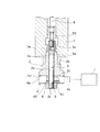
図2は本発明による工作機械用スピンドルのツール引込み力測定システムの一例を示す機能ブロック図、図3は図2に示すツール引込み力測定システムを構成するコンピュータ及び引込み力検出信号処理部の構成図、図4は図2に示すツール引込み力測定システムの動作手順を示すフローチャートである。
以下では、これらの図面を参照して、本発明にかかるスピンドルのツール引込み力測定システムの実施の形態について説明し、同時に本発明にかかるスピンドルのツール引込み力測定用プログラムの実施例についても説明する。
【0019】
本実施例における工作機械用スピンドルのツール引込み力測定システムは、具体的には、図3に示したパーソナルコンピュータ(以下、パソコンと略称する)10と、工具引込み装置のツール引込み力を検出するロードセル323と、このロードセル323から出力される検出信号を所定の時間間隔でサンプリングするサンプル・ホールド回路14と、このサンプル・ホールド回路14でホールドされたアナログ信号値をサンプリング毎にディジタル信号に変換して前記パソコン10に出力するA/D変換回路15等とを含んで構成されている。
【0020】
前記パソコン10は、図3に示すように、全体を制御し管理すると共にA/D変換回路14からのディジタル信号を基に所定の引込み力測定処理を可能にするCPU101と、このCPU101に接続されたメインメモリ102と、CPU101に接続されたCRT等の表示部103と、CPU101に接続されたキーボード及びマウス等からなる入力部104と、CPU101に接続されたハードディスク装置105などを備え、そして、後で詳しく説明する図2に示したグラフ生成手段202、グラフ表示制御手段203、第1表示処理手段205、第2表示処理手段206等の各機能は、パソコン10のメインメモリ102にハードディスク装置105から所定のプログラムデータをロードし、このプログラムでCPU101を動作させることにより実現される。
また、CPU101には、表示部103に表示されたグラフその他の測定結果をプリントアウトするプリンタ106が接続されている。
【0021】
本実施の形態におけるスピンドルのツール引込み力測定システムは、図2に示すように、工作機械のスピンドル30内に設けられた工具引込み装置31と、この工具引込み装置31によりスピンドル30のテーパ穴30aに係脱可能に装着され、工具引込み装置31の引込み力を検出するロードセル323を有する引込み力測定ツール32と、ロードセル323から出力される信号のうちの引込み力に関係する検出信号成分のみを通過させる帯域通過フィルタ(BPF)12と、この帯域通過フィルタ12を通過した検出信号を電圧に変化して増幅する増幅回路13と、この増幅回路13から出力される検出信号を所定の時間間隔でサンプリングするサンプル・ホールド回路14と、このサンプル・ホールド回路14でホールドされたアナログ信号値をサンプリング毎にディジタル信号に変換するA/D変換回路15と、記憶手段201と、グラフ生成手段202と、グラフ表示制御手段203と、入力手段204と、第1表示処理手段205及び第2表示処理手段206と、表示部207と、測定値表示制御手段208と、これらの各構成要素を制御し管理する制御手段209(図3に示すCPU101に相当する)を含んで構成されている。
【0022】
前記記憶手段201は、A/D変換回路15で変換されたディジタル信号を記憶するもので、図3に示すメインメモリ102から構成される。
前記グラフ生成手段202は、表示部207にグラフの引込み力を表す縦軸と時間を表す横軸及びそのスケールを描くためのグラフ表示情報を生成するものである。
【0023】
前記グラフ表示制御手段203は、グラフ生成手段202で生成されたグラフ表示情報を基にグラフの縦軸と横軸及びそのスケールを表示部207に表示するとともに記憶手段201に格納されたディジタル信号を順次読み出して折線グラフ表示データに変換し、この折線グラフ表示データに基づいて工具引込み装置31の引込み動作開始から終了までの時間に対する引込み力の変化を表す折線グラフとして表示部207に表示するものである。
前記入力手段204は、少なくとも表示部207に表示された折線グラフ上の任意の点を指示する機能、及び表示部207に表示された水平線及び垂直線をドラッグさせる機能を有するもので、図3に示した入力部104に相当し、マウスまたはキーボードなどから構成される。
【0024】
前記第1表示処理手段205は、入力手段204で指示された折線グラフ上の任意の点をクリックすることにより、このクリック点を通って折線グラフの引込み力を表す縦軸に直角な水平線及びクリック点を通って折線グラフの時間を表す横軸に直角な垂直線を表示部207に表示し、同時に、水平線が直交する縦軸上の引込み力と垂直線が直交する横軸上の時間を表示部207に数字表示するものである。
【0025】
前記第2表示処理手段206は、入力手段204の操作で水平線または垂直線にマウスポインタを合わせた後、この入力手段204をドラッグ操作することにより水平線または垂直線を折線グラフに沿い移動して、表示部207に表示し、同時に、この水平線または垂直線の移動位置における引込み力及び時間の各値を表示部207に数字表示するものである。
【0026】
前記測定値表示制御手段208は、サンプル・ホールド回路14のサンプリング動作開始から終了までの間で所定の時間間隔でサンプリングされる各サンプル時点のサンプル経過時間をサンプリング毎に表示部207に表示された表52の時間欄に時間系列で数字表示すると同時に、各サンプル時点のサンプル経過時間に対応して記憶手段201に格納された測定値を表示部207に表示された表52の測定値欄に時間系列で数字表示するものである。
【0027】
前記引込み力測定ツール32は、図2に示すように、引込み力測定用のツール本体321と、ツール本体引込み用の引込み部材322と、工具引込み装置31の引込み力を検出するロードセル323等を備えている。
【0028】
前記ツール本体321は、図2に示すように、スピンドル30のテーパ穴30aに嵌合されるテーパ付きシャンク部321aと、このシャンク部321aの大径側に軸線を一致して一体に設けた把持用フランジ部321bと、この把持用フランジ部321bの反テーパシャンク部側に軸線を一致して一体に設けた、把持用フランジ部321bより大径のロードセル設置部321cとを有し、これらシャンク部321a、把持用フランジ部321b及びロードセル設置部321cの軸心には、前記引込み部材322が挿通される穴321dが形成されている。
【0029】
前記引込み部材322は、図2に示すように、ツール本体321の穴321dに挿通される軸部322aと、この軸部322aの後端に一体に設けられ、かつ穴321dの径より大きい外径のプルスタッド結合部322bと、ツール本体321の穴321dから突出する軸部322aの前端に設けた雄ねじ部322cとを有し、前記プルスタッド結合部322bにはプルスタッド322dが螺着されている。
【0030】
前記ロードセル323は、図2に示すように、内部が中空のドーナツ盤状を呈する弾性体323aと、この弾性体323aの内壁面に貼り付けた、抵抗線または半導体などからなる圧力センサ323bと、弾性体323aの外周部に設けられ、前記圧力センサ323bと電気的に接続される端子部323cとを備えている。
【0031】
前記ロードセル323をツール本体321に組み付ける場合は、図2に示すように、ロードセル323をロードセル設置部321cの取付面321c1に重ね合わせ、その後、ツール本体321の後端から差し込んだ引込み部材322の軸部322aをロードセル323の中心穴323dに挿通し、この中心穴323dから突出する雄ねじ部322cにナット33を螺合して締め付けることにより、ロードセル323をツール本体321のロードセル設置部321cに固定する。
その後、ナット33にその半径方向から螺合した止めねじ34を締め付けて、ナット33の回り止めを行う。
【0032】
次に、上記のように構成された本実施に形態の動作について、図2〜図7を参照しながら説明する。
まず、図示省略した自動工具交換装置の交換アームを利用して、引込み力測定ツール32のシャンク部321aをスピンドル30のテーパ穴30aに差し込む。その後、工具引込み装置31を動作させることにより、そのクランプ部材311でツール本体321のプルスタッド322dをクランプし、これと同時に、上記交換アームをツール本体321から離して退避させる。しかる後、工具引込み装置31により引込み力測定ツール32の引込み部材322を後方へ引っ張る。
これにより、ツール本体32のシャンク部321aは、工具引込み装置31が有する引込み力でスピンドル30のテーパ穴30aに嵌合されると同時に、ロードセル323の弾性体323aに引込み部材322及びナット33を通して工具引込み装置31の引込み力が作用する。このため、弾性体323aには引込み力に比例した弾性歪が生じ、この歪は圧力センサ323bにより電気信号に変換される(ステップS1)。
【0033】
上記圧力センサ323bから出力される信号のうち、引込み力に関係する検出信号成分は帯域通過フィルタ12を通過して、増幅回路13に入力される。この増幅回路13では、帯域通過フィルタ12を通過した検出信号を電圧に変化して増幅し、サンプル・ホールド回路14に出力する。
このサンプル・ホールド回路14では、増幅回路13から出力される検出信号を所定の時間間隔、例えば、約0.20sec以下の時間間隔で、工具引込み装置31の引込み動作開始から終了までの時間、例えば5secの間サンプリングされる(ステップS2)。その後、サンプル・ホールド回路14でホールドされたアナログ信号値はA/D変換回路15によりサンプリング毎にディジタル信号に変換される(ステップS3)。
【0034】
上記A/D変換回路15で変換されたディジタル信号は、図2に示す制御手段207を通して記憶手段201に取り込まれ、記憶手段201に順次に格納される(ステップS4)。
また、グラフ生成手段202では、図5に示すように、表示部207にグラフの引込み力を表す縦軸と時間を表す横軸及びそのスケールを描くためのグラフ表示情報を生成する(ステップS5)。
【0035】
一方、グラフ表示制御手段203では、グラフ生成手段202で生成されたグラフ表示情報を基にグラフの縦軸と横軸及びそのスケールを表示部207に図5に示すように表示する(ステップS6)。これと同時に、記憶手段201に格納されたディジタル信号を順次読み出して折線グラフ表示データ(折線グラフ表示用のアナログ信号)に変換し、この折線グラフ表示データを基にして工具引込み装置31の引込み動作開始から終了までの時間(t)に対する引込み力(KN)の変化を表す折線グラフ51として、図5に示すように表示部207に表示する(ステップS7)。
【0036】
また、測定値表示制御手段208では、サンプル・ホールド回路14のサンプリング動作開始から終了までの間(約5秒)で、約0.20secの時間間隔でサンプリングされる各サンプル時点のサンプル経過時間をサンプリング毎に表示部207のグラフ表示領域外に図5に示すように表示された表52の時間欄に時間系列で数字表示する。これと同時に、各サンプル時点のサンプル経過時間に対応するサンプリング値、すなわち、サンプリング毎にディジタル信号に変換され、かつ記憶手段201に格納された測定値を、表示部207に表示された図5に示す表52の測定値欄に時間系列で数字表示する(ステップS8)。
【0037】
次に、第1表示処理手段205及び第2表示処理手段206の動作について、図2及び図4〜図7を参照して説明する。
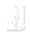
例えば、入力手段204を構成するマウスを操作することにより、表示部207の画面上に表示されているマウスポインタ60を図6に示す折線グラフ51上に移動して、その任意の点P1を指示しクリックする(ステップS9)。これにより、第1表示処理手段205が動作を開始する。
この第1表示処理手段205が動作されると、上記クリック点P1を通ってグ折線ラフ51の引込み力を表す縦軸に直角な水平線61と、クリック点P1を通って折線グラフ51の時間を表す横軸に直角な垂直線62を表示部207にそれぞれ表示する(ステップS10)。その後、水平線61が直交する縦軸上の引込み力値と垂直線62が直交する横軸上の時間値を表示部207に数字表示する(ステップS11)。
【0038】
なお、第1表示処理手段205により表示された水平線61及び垂直線62は、これら水平線61及び垂直線62をマウスポインタ60で指示して、再度クリックすれば、これら水平線61と垂直線62及びこれら水平線61と垂直線62に対応する各値も表示部207の画面上から消去されるようになっている。
【0039】
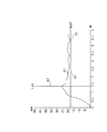
水平線61及び垂直線62が表示部207に表示された状態において、入力手段204を構成するマウスを操作することにより、表示部207の画面上に表示されているマウスポインタ60を図6に示す水平線61(または垂直線62)に合わせ、この入力手段204をドラッグ操作する(ステップS12)。これにより、第2表示処理手段206が動作を開始する。
この第2表示処理手段206が動作されると、入力手段204のドラッグ操作に伴い、水平線61は図7に示すように鉛直方向に平行移動される。そして、この水平線61が図7に示すように折線グラフ51と交差する点P2でドラッグを解除すると、水平線61は点P2と交差するように表示部207に表示されると同時に、この水平線61の移動位置における引込み力値が表示部207に図7に示すように数字表示される(ステップS13)。
なお,上記の説明では、水平線61をドラッグする場合について述べたが、垂直線62をドラッグする場合においても水平線61と同様に行われるので,その説明は省略する。
【0040】
このような本実施の形態におけるスピンドルのツール引込み力測定システムによれば、グラフ表示制御手段203により、グラフ生成手段202で生成されたグラフ表示情報を基にグラフの縦軸と横軸及びそのスケールを表示部207に表示すると同時に、記憶手段201に格納されたディジタル信号を順次読み出して折線グラフ表示データ(折線グラフ表示用のアナログ信号)に変換し、この折線グラフ表示データを基にして工具引込み装置31の引込み動作開始から終了までの時間(t)に対する引込み力(KN)の変化を表す折線グラフ51として、表示部207に表示するように構成したので、工具引込み装置31の引込み動作開始から終了までの引込み力の変化及び挙動を容易に把握することができる。
【0041】
また,本実施の形態によれば、測定値表示制御手段208により、サンプル・ホールド回路14のサンプリング動作開始から終了までの間で所定の時間間隔でサンプリングされる各サンプル時点のサンプル経過時間をサンプリング毎に表示部207に表示された表52の時間欄に時間系列で数字表示すると同時に、各サンプル時点のサンプル経過時間に対応して記憶手段201に格納された測定値を表示部207に表示された表52の測定値欄に時間系列で数字表示するようにしたので、工具引込み装置31の引込み動作開始から終了までの引込み力の変化を数値的に把握することができる。
【0042】
また,本実施の形態によれば、入力手段204で指示された折線グラフ上の任意の点をクリックすることにより第1表示処理手段205を動作させ、これにより、このクリック点を通ってグラフの引込み力を表す縦軸に直角な水平線61及びクリック点を通ってグラフの時間を表す横軸に直角な垂直線62を表示部207に表示するとともに、水平線61が直交する縦軸上の引込み力値と垂直線62が直交する横軸上の時間値を表示部207に数字表示するように構成したので、工具引込み装置31の引込み動作開始から終了までの任意の点の引込み力を容易にピックアップして表示することができる。
【0043】
また,本実施の形態によれば、入力手段204の操作で水平線または垂直線にマウスポインタを合わせてドラッグ操作することにより第2表示処理手段206を動作させ、これにより、水平線61または垂直線62を折線グラフ51に沿い移動して表示部207に表示するとともに、この水平線61または垂直線62の移動位置における引込み力値及び時間値を表示部207に数字表示するように構成したので、工具引込み装置31の引込み動作開始から終了までの任意の点の引込み力及び時間をピックアップして個別に表示することができる。
【0044】
【発明の効果】
以上説明したように本発明にかかるスピンドルのツール引込み力測定システム並びにスピンドルのツール引込み力測定用プログラムによれば、グラフ表示制御手段またはグラフ表示制御ステップにより、グラフ生成手段またはグラフ生成ステップで生成されたグラフ表示情報を基にグラフの縦軸と横軸及びそのスケールを表示部に表示するとともに、ロードセルからの検出信号をディジタル信号に変換し、該ディジタル信号を折線グラフ表示データに変換するとともに該折線グラフ表示データに基づいて工具引込み装置の引込み動作開始から終了までの時間に対する引込み力の変化を表す折線グラフとして表示部に表示するように構成したので、工具引込み装置の引込み動作開始から終了までの引込み力の変化及び挙動を容易に把握することができる。
【0045】
また,本発明にかかるスピンドルのツール引込み力測定システムによれば、測定値表示制御手段により、サンプル・ホールド回路のサンプリング動作開始から終了までの間で所定の時間間隔でサンプリングされる各サンプル時点のサンプル経過時間をサンプリング毎に表示部に表示された表の時間欄に時間系列で数字表示するとともに、各サンプル時点のサンプル経過時間に対応して記憶手段に格納された測定値を表示部に表示された表の測定値欄に時間系列で数字表示するように構成したので、工具引込み装置の引込み動作開始から終了までの引込み力の変化を数値的に把握することができる。
【0046】
また,本発明にかかるスピンドルのツール引込み力測定システム並びにスピンドルのツール引込み力測定用プログラムによれば、入力手段で指示された折線グラフ上の任意の点をクリックすることにより第1表示処理手段または第1表示処置ステップを動作させ、これにより、このクリック点を通ってグラフの引込み力を表す縦軸に直角な水平線及びクリック点を通ってグラフの時間を表す横軸に直角な垂直線を表示部に表示するとともに、水平線が直交する縦軸上の引込み力値と垂直線が直交する横軸上の時間値を表示部に数字表示するように構成したので、工具引込み装置の引込み動作開始から終了までの任意の点の引込み力を容易にピックアップして表示することができる。
【0047】
また,本発明にかかるスピンドルのツール引込み力測定システム並びにスピンドルのツール引込み力測定用プログラムによれば、入力手段の操作で水平線または垂直線にマウスポインタを合わせてドラッグ操作することにより第2表示処理手段または第2表示処理ステップを動作させ、これにより、水平線または垂直線を折線グラフに沿い移動して表示部に表示するとともに、この水平線または垂直線の移動位置における引込み力値及び時間値を表示部に数字表示するように構成したので、工具引込み装置の引込み動作開始から終了までの任意の点の引込み力及び時間をピックアップして個別に表示することができる。
【図面の簡単な説明】
【図1】引込み力測定ツールの一例を示す説明用縦断面図である。
【図2】本発明による工作機械用スピンドルのツール引込み力測定システムの一例を示す機能ブロック図である。
【図3】図2に示すツール引込み力測定システムを構成するコンピュータ及び引込み力検出信号処理部の構成図である。
【図4】図2に示すツール引込み力測定システムの動作手順を示すフローチャートである。
【図5】本実施の形態における引込み力と時間との関係を折線グラフ及び表にして表示部に表示した場合の一例を示す説明図である。
【図6】本実施の形態における引込み力と時間との関係を折線グラフにして表示部に表示し、かつ水平線と垂直線を同時に表示した場合の一例を示す説明図である。
【図7】本実施の形態における引込み力と時間との関係を折線グラフにして表示部に表示し、かつ水平線または垂直線の一方をドラッグして表示した場合の一例を示す説明図である。
【符号の説明】
10 パソコン
12 帯域通過フィルタ(BPF)
13 増幅回路
14 サンプル・ホールド回路
15 A/D変換回路
30 スピンドル
31 工具引込み装置
32 引込み力測定ツール
321 ツール本体
322 引込み部材
323 ロードセル
201 記憶手段
202 グラフ生成手段
203 グラフ表示制御手段
204 入力手段
205 第1表示処理手段
206 第2表示処理手段
207 表示部
208 測定値表示制御手段
209 制御手段[0001]
TECHNICAL FIELD OF THE INVENTION
The present invention relates to a spindle tool retraction force measuring system for measuring a tool retraction force to a spindle by a tool retraction device provided in a spindle of a machine tool such as a machining center, and a program for measuring a tool retraction force of a spindle. .
[0002]
[Prior art]
2. Description of the Related Art Conventionally, as a means for measuring a retraction force of a tool retraction device provided in a spindle of a machine tool, a retraction force measurement tool is known (for example, see Patent Document 1).
[0003]
[Patent Document 1]
JP-A-2002-137148
[0004]
As shown in FIG. 1, the retraction
As shown in FIG. 1, the tool
[0005]
As shown in FIG. 1, the retracting
[0006]
As shown in FIG. 1, the
When assembling the
[0007]
When measuring the tool retraction force of the spindle using such a retraction
[0008]
[Problems to be solved by the invention]
However, the conventional retracting force measuring method as described above outputs an electric signal from the
[0009]
SUMMARY OF THE INVENTION The present invention has been made to solve the above-described problems, and an object of the present invention is to make it possible to easily grasp the change and behavior of the retraction force from the start to the end of the retraction operation of the tool retraction device, and to realize the tool retraction device. An object of the present invention is to provide a spindle tool retraction force measurement system and a spindle tool retraction force measurement program that can easily pick up and display the retraction force at any point from the start to the end of the retraction operation.
[0010]
[Means for Solving the Problems]
In order to achieve the above object, the invention according to
[0011]
According to a second aspect of the present invention, in the system for measuring a tool retraction force of a spindle according to the first aspect, an input unit having a function of designating an arbitrary point on a line graph displayed on the display unit; Clicking an arbitrary point on the graph, the horizontal axis perpendicular to the vertical axis representing the retraction force of the line graph through the click point and the horizontal axis representing the time of the line graph passing through the click point A vertical line perpendicular to the horizontal line is generated and displayed on the display unit, and the retraction force value on the vertical axis where the horizontal line is orthogonal and the time value on the horizontal axis where the vertical line is orthogonal are numerically displayed on the display unit. And a first display processing unit.
[0012]
According to a third aspect of the present invention, in the spindle tool retraction force measuring system according to the second aspect, the input unit has a function of dragging the horizontal line and the vertical line displayed on the display unit. By dragging, the horizontal line or the vertical line is moved along the line graph and displayed on the display unit, and the retraction force value or the time value at the moving position of the horizontal line or the vertical line is numerically displayed on the display unit. It is characterized by comprising two display processing means.
[0013]
According to a fourth aspect of the present invention, in the system for measuring the tool retraction force of the spindle according to the first aspect, the sample progress at each sample time point sampled at a predetermined time interval from the start to the end of the sampling operation of the sample and hold circuit. The time is numerically displayed in the time column of the table displayed on the display unit for each sampling in a time series, and the measured value stored in the storage unit corresponding to the sample elapsed time at each sample time is displayed on the display unit. 3. The tool retraction force measuring system for a spindle according to
[0014]
According to a fifth aspect of the present invention, the pull-in force of the tool retracting device when the retracting force measuring tool is retracted into the spindle by the tool retracting device provided in the spindle of the machine tool is detected by the load cell, and is detected by the load cell. A program for measuring a tool retraction force of a spindle based on a signal, a graph generating a vertical axis representing a retraction force of the graph, a horizontal axis representing time on a display unit, and graph display information for drawing the scale thereof. Generating a vertical axis, a horizontal axis and a scale of the graph on a display unit based on the graph display information generated in the graph generating step, and converting a detection signal from the load cell into a digital signal; Converting the signal into line graph display data and the tool retracting device based on the line graph display data Characterized in that it comprises a graph display processing step of displaying on the display unit as a line graph representing the change in pull force versus time to end the pull-in operation starts.
[0015]
According to a sixth aspect of the present invention, in the program for measuring a tool pull-in force of the spindle according to the fifth aspect, an arbitrary point on the polygonal line graph displayed on the display section is clicked by the input means to pass through the clicked point. A horizontal line perpendicular to the vertical axis representing the retraction force of the line graph and a vertical line perpendicular to the horizontal axis representing the time of the line graph passing through the click point are displayed on the display unit, and the vertical line where the horizontal line is perpendicular to the vertical line. A first display processing step of numerically displaying, on the display unit, a time value on the horizontal axis at which the vertical withdrawal force value is orthogonal to the vertical line.
[0016]
According to a seventh aspect of the present invention, in the program for measuring a tool retraction force of a spindle according to the sixth aspect, the horizontal line and the vertical line are moved along the line graph by dragging the input means and displayed on the display unit. And a second display processing step of numerically displaying the retraction force value or the time value at the moving position of the horizontal line or the vertical line on the display unit.
[0017]
According to an eighth aspect of the present invention, in the program for measuring a tool retraction force of a spindle according to the fifth aspect, the detection signal output from the load cell is sampled at predetermined time intervals by a sample and hold circuit. The held analog signal is converted into a digital signal by the A / D conversion circuit for each sampling.
[0018]
BEST MODE FOR CARRYING OUT THE INVENTION
Next, embodiments of the present invention will be described with reference to the drawings.
FIG. 2 is a functional block diagram showing an example of a tool retracting force measuring system for a machine tool spindle according to the present invention, and FIG. 3 is a configuration diagram of a computer and a retracting force detection signal processing section constituting the tool retracting force measuring system shown in FIG. FIG. 4 is a flowchart showing the operation procedure of the tool pull-in force measuring system shown in FIG.
Hereinafter, with reference to these drawings, an embodiment of a system for measuring a tool retraction force of a spindle according to the present invention will be described, and an example of a program for measuring a tool retraction force of a spindle according to the present invention will also be described. .
[0019]
Specifically, the tool retraction force measuring system for a machine tool spindle according to the present embodiment includes a personal computer (hereinafter abbreviated as a personal computer) 10 shown in FIG. 3 and a load cell for detecting a tool retraction force of a tool retraction device. H.323, a sample-and-
[0020]
As shown in FIG. 3, the
Further, a printer 106 for printing out a graph and other measurement results displayed on the
[0021]
As shown in FIG. 2, the tool retracting force measuring system for a spindle according to the present embodiment includes a
[0022]
The storage means 201 stores the digital signal converted by the A /
The graph generating means 202 generates graph display information for drawing a vertical axis representing a drawing force of the graph, a horizontal axis representing time, and a scale thereof on the
[0023]
The graph display control means 203 displays the vertical axis, the horizontal axis and the scale of the graph on the
The input means 204 has at least a function of designating an arbitrary point on the line graph displayed on the
[0024]
By clicking an arbitrary point on the line graph designated by the
[0025]
The second display processing means 206 moves the horizontal or vertical line along the line graph by dragging the input means 204 after the mouse pointer is moved to the horizontal or vertical line by operating the input means 204, This is displayed on the
[0026]
The measured value display control means 208 displays the sample elapsed time at each sample point sampled at a predetermined time interval from the start to the end of the sampling operation of the sample and hold
[0027]
As shown in FIG. 2, the retraction
[0028]
As shown in FIG. 2, the tool
[0029]
As shown in FIG. 2, the
[0030]
As shown in FIG. 2, the
[0031]
When assembling the
Thereafter, the
[0032]
Next, the operation of the present embodiment configured as described above will be described with reference to FIGS.
First, the
Thereby, the
[0033]
Among the signals output from the
In the sample and hold
[0034]
The digital signal converted by the A /
Further, as shown in FIG. 5, the graph generation means 202 generates graph display information for drawing the vertical axis representing the retraction force of the graph, the horizontal axis representing time, and the scale thereof on the display unit 207 (step S5). .
[0035]
On the other hand, the graph
[0036]
Further, the measured value display control means 208 calculates the sample elapsed time at each sample point at a time interval of about 0.20 sec from the start to the end of the sampling operation of the sample and hold circuit 14 (about 5 seconds). For each sampling, numerals are displayed in time series in the time column of the table 52 displayed as shown in FIG. 5 outside the graph display area of the
[0037]
Next, the operation of the first display processing means 205 and the second display processing means 206 will be described with reference to FIG. 2 and FIGS.
For example, by operating the mouse constituting the
When the first display processing means 205 is operated, the time of the
[0038]
Note that the
[0039]
In a state where the
When the second display processing means 206 is operated, the
In the above description, the case where the
[0040]
According to the spindle tool pull-in force measuring system according to the present embodiment, the graph display control means 203 uses the graph display information generated by the graph generation means 202 to display the vertical and horizontal axes and the scale of the graph. Is displayed on the
[0041]
Further, according to the present embodiment, the measured value display control means 208 samples the sample elapsed time at each sample point sampled at a predetermined time interval from the start to the end of the sampling operation of the sample and hold
[0042]
Further, according to the present embodiment, the first display processing means 205 is operated by clicking an arbitrary point on the polygonal line graph designated by the input means 204, whereby the first display processing means 205 is operated through the click point. A
[0043]
Further, according to the present embodiment, the second
[0044]
【The invention's effect】
As described above, according to the spindle tool retraction force measurement system and the spindle tool retraction force measurement program according to the present invention, the graph display control means or the graph display control step generates the graph by the graph generation means or the graph generation step. Based on the graph display information, the vertical and horizontal axes of the graph and the scale thereof are displayed on the display unit, the detection signal from the load cell is converted into a digital signal, and the digital signal is converted into linear graph display data. Based on the line graph display data, it is configured to display on the display unit a line graph representing the change in the retraction force with respect to the time from the start to the end of the retraction operation of the tool retraction device. To easily grasp the change and behavior of the pull-in force It can be.
[0045]
Further, according to the tool retraction force measuring system for a spindle according to the present invention, the measured value display control means controls the sampling time of each sample point sampled at a predetermined time interval from the start to the end of the sampling operation of the sample and hold circuit. The sample elapsed time is numerically displayed in time series in the time column of the table displayed on the display unit for each sampling, and the measured value stored in the storage means is displayed on the display unit corresponding to the sample elapsed time at each sample time. Since a numerical value is displayed in a time series in the measured value column of the table, the change in the retraction force from the start to the end of the retraction operation of the tool retraction device can be grasped numerically.
[0046]
According to the spindle tool retraction force measurement system and the spindle tool retraction force measurement program of the present invention, the first display processing means or the first display processing means can be clicked by clicking an arbitrary point on the line graph specified by the input means. Activating the first display action step, thereby displaying a horizontal line perpendicular to the vertical axis representing the retraction force of the graph through this click point and a vertical line perpendicular to the horizontal axis representing the time of the graph through the click point. And the time value on the horizontal axis, where the horizontal line is perpendicular, and the time value, on the horizontal axis, where the vertical line is perpendicular, are displayed on the display unit. The pull-in force at any point up to the end can be easily picked up and displayed.
[0047]
According to the spindle tool retraction force measurement system and the spindle tool retraction force measurement program of the present invention, the second display processing can be performed by dragging the mouse pointer to a horizontal or vertical line by operating the input means. Operating the means or the second display processing step, whereby the horizontal line or the vertical line is moved along the line graph and displayed on the display unit, and the retraction force value and the time value at the moving position of the horizontal line or the vertical line are displayed. Since the unit is configured to display numbers, the retraction force and time at any point from the start to the end of the retraction operation of the tool retraction device can be picked up and individually displayed.
[Brief description of the drawings]
FIG. 1 is an explanatory longitudinal sectional view showing an example of a retraction force measuring tool.
FIG. 2 is a functional block diagram showing an example of a tool retraction force measuring system for a machine tool spindle according to the present invention.
FIG. 3 is a configuration diagram of a computer and a pull-in force detection signal processing unit constituting the tool pull-in force measuring system shown in FIG. 2;
FIG. 4 is a flowchart showing an operation procedure of the tool retracting force measuring system shown in FIG.
FIG. 5 is an explanatory diagram showing an example of a case where the relationship between the pull-in force and time in the present embodiment is displayed on a display unit as a line graph and a table.
FIG. 6 is an explanatory diagram showing an example of the case where the relationship between the pull-in force and time in the present embodiment is displayed as a line graph on the display unit, and a horizontal line and a vertical line are simultaneously displayed.
FIG. 7 is an explanatory diagram showing an example of a case where the relationship between the pull-in force and time in the present embodiment is displayed as a line graph on the display unit, and one of a horizontal line and a vertical line is dragged and displayed.
[Explanation of symbols]
10 PC
12. Bandpass filter (BPF)
13 Amplification circuit
14. Sample and hold circuit
15 A / D conversion circuit
30 spindle
31 Tool retracting device
32 Retraction Force Measurement Tool
321 Tool body
322 Retraction member
323 load cell
201 storage means
202 Graph generation means
203 Graph display control means
204 input means
205 first display processing means
206 second display processing means
207 Display
208 Measured value display control means
209 Control means
Claims (8)
表示部と、
前記工具引込み装置による前記ツール本体の引込み動作開始から終了までの間に前記ロードセルから出力されるアナログ信号を所定の時間間隔でサンプリングするサンプル・ホールド回路と、
前記サンプル・ホールド回路でホールドされたアナログ信号値をサンプリング毎にディジタル信号に変換するA/D変換回路と、
前記A/D変換回路で変換されたディジタル信号を格納する記憶手段と、
前記表示部にグラフの引込み力を表す縦軸と時間を表す横軸及びそのスケールを描くためのグラフ表示情報を生成するグラフ生成手段と、
前記グラフ生成手段で生成されたグラフ表示情報を基にグラフの縦軸と横軸及びそのスケールを前記表示部に表示するとともに前記記憶手段に格納されたディジタル信号を順次読み出して折線グラフ表示データに変換し、該折線グラフ表示データに基づいて前記工具引込み装置の引込み動作開始から終了までの時間に対する引込み力の変化を表す折線グラフとして前記表示部に表示するグラフ表示制御手段と、を備えることを特徴とするスピンドルのツール引込み力測定システム。A tool retraction device provided in a spindle of the machine tool; and a retraction force measurement tool that is removably attached to the spindle by the tool retraction device. A tool main body for measuring a retraction force to be drawn into, and a tool retraction force measurement system for a spindle having a load cell provided integrally with the tool main body and detecting a tool retraction force of the tool retraction device,
A display unit,
A sample and hold circuit that samples an analog signal output from the load cell at a predetermined time interval from the start to the end of the drawing operation of the tool main body by the tool drawing device,
An A / D conversion circuit for converting the analog signal value held by the sample and hold circuit into a digital signal for each sampling;
Storage means for storing the digital signal converted by the A / D conversion circuit;
Graph generation means for generating graph display information for drawing the vertical axis representing the pull-in force of the graph and the horizontal axis representing the time and the scale on the display unit,
Based on the graph display information generated by the graph generation means, the vertical and horizontal axes of the graph and its scale are displayed on the display unit, and the digital signals stored in the storage means are sequentially read out and converted to linear graph display data. And a graph display control means for displaying on the display unit a line graph representing a change in retraction force with respect to time from the start to the end of the retraction operation of the tool retraction device based on the line graph display data. Characteristic spindle tool retraction force measurement system.
表示部にグラフの引込み力を表す縦軸と時間を表す横軸及びそのスケールを描くためのグラフ表示情報を生成するグラフ生成ステップと、
前記グラフ生成ステップで生成されたグラフ表示情報を基にグラフの縦軸と横軸及びそのスケールを表示部に描画するとともに前記ロードセルからの検出信号をディジタル信号に変換し、該ディジタル信号を折線グラフ表示データに変換するとともに該折線グラフ表示データに基づいて前記工具引込み装置の引込み動作開始から終了までの時間に対する引込み力の変化を表す折線グラフとして表示部に表示するグラフ表示処理ステップと、を備えることを特徴とするスピンドルのツール引込み力測定用プログラム。A retracting force of the tool retracting device when the retracting force measuring tool is retracted into the spindle is detected by a load cell by a tool retracting device provided in a spindle of the machine tool. A program for measuring the retraction force,
A graph generation step of generating graph display information for drawing a vertical axis representing a drawing force of the graph, a horizontal axis representing time on the display unit, and a scale thereof,
Based on the graph display information generated in the graph generation step, the vertical and horizontal axes of the graph and its scale are drawn on a display unit, and the detection signal from the load cell is converted into a digital signal. A graph display processing step of converting the data into display data and displaying on the display unit a line graph representing a change in the retraction force with respect to the time from the start to the end of the retraction operation of the tool retraction device based on the line graph display data. A program for measuring a tool pull-in force of a spindle, characterized in that:
Priority Applications (1)
| Application Number | Priority Date | Filing Date | Title |
|---|---|---|---|
| JP2003063185A JP2004268205A (en) | 2003-03-10 | 2003-03-10 | Tool pulling-in force measuring system of spindle and tool pulling-in force measuring program of spindle |
Applications Claiming Priority (1)
| Application Number | Priority Date | Filing Date | Title |
|---|---|---|---|
| JP2003063185A JP2004268205A (en) | 2003-03-10 | 2003-03-10 | Tool pulling-in force measuring system of spindle and tool pulling-in force measuring program of spindle |
Publications (1)
| Publication Number | Publication Date |
|---|---|
| JP2004268205A true JP2004268205A (en) | 2004-09-30 |
Family
ID=33124831
Family Applications (1)
| Application Number | Title | Priority Date | Filing Date |
|---|---|---|---|
| JP2003063185A Pending JP2004268205A (en) | 2003-03-10 | 2003-03-10 | Tool pulling-in force measuring system of spindle and tool pulling-in force measuring program of spindle |
Country Status (1)
| Country | Link |
|---|---|
| JP (1) | JP2004268205A (en) |
Cited By (3)
| Publication number | Priority date | Publication date | Assignee | Title |
|---|---|---|---|---|
| CN102179723A (en) * | 2011-03-08 | 2011-09-14 | 哈尔滨先锋机电技术开发有限公司 | Radiocommunication-based online measuring device of numerical control machine |
| US8579561B2 (en) | 2007-03-29 | 2013-11-12 | Mitsubishi Heavy Industries, Ltd. | Spindle device of machine tool |
| JP2018519170A (en) * | 2015-05-08 | 2018-07-19 | サンドビック インテレクチュアル プロパティー アクティエボラーグ | Method for determining the pull-out of a cutting tool and a rotatable tool holder for the cutting tool |
-
2003
- 2003-03-10 JP JP2003063185A patent/JP2004268205A/en active Pending
Cited By (4)
| Publication number | Priority date | Publication date | Assignee | Title |
|---|---|---|---|---|
| US8579561B2 (en) | 2007-03-29 | 2013-11-12 | Mitsubishi Heavy Industries, Ltd. | Spindle device of machine tool |
| CN102179723A (en) * | 2011-03-08 | 2011-09-14 | 哈尔滨先锋机电技术开发有限公司 | Radiocommunication-based online measuring device of numerical control machine |
| CN102179723B (en) * | 2011-03-08 | 2015-04-01 | 哈尔滨先锋机电技术开发有限公司 | Radiocommunication-based online measuring device of numerical control machine |
| JP2018519170A (en) * | 2015-05-08 | 2018-07-19 | サンドビック インテレクチュアル プロパティー アクティエボラーグ | Method for determining the pull-out of a cutting tool and a rotatable tool holder for the cutting tool |
Similar Documents
| Publication | Publication Date | Title |
|---|---|---|
| US6628113B2 (en) | Surge current measurement | |
| CN101732039B (en) | Fixing device for radial pulse wave detection sensor | |
| CN106908642B (en) | A probe, oscilloscope, motion recognition system and method | |
| JP2004268205A (en) | Tool pulling-in force measuring system of spindle and tool pulling-in force measuring program of spindle | |
| JP2000197617A (en) | Method and apparatus for detecting lead drop of biological signal measuring instrument | |
| CN204136868U (en) | Grip gear detection device | |
| CN109444386B (en) | Seed cotton moisture regain measuring device | |
| CN214843978U (en) | Detection device | |
| JP2005091086A (en) | Bolt axial force detector, bolt with bolt axial force detector, bolt and bolt tightening management method | |
| JP6477969B2 (en) | Measuring device and material testing machine | |
| CN104049118B (en) | Oscilloscope that displays waveform measurement parameters in trend graphs | |
| CN106908643A (en) | A kind of probe, oscillograph, movement recognition system and method | |
| US6239596B1 (en) | Total magnetic flux measuring device | |
| CN112051439B (en) | Voltage measuring instrument | |
| WO1995031313A1 (en) | Dual-peak torque measuring apparatus | |
| JPH07113603A (en) | Inside measuring device | |
| JPH08159817A (en) | Small data collection device | |
| CN212513401U (en) | Soil temperature measuring device | |
| JP4455938B2 (en) | Voltage measuring device | |
| WO2021047884A1 (en) | Non-invasive thermometer | |
| JPH08233665A (en) | Thermoelectric thermometer | |
| CN210981540U (en) | Temperature detector capable of accessing Internet of things | |
| JP2005321288A (en) | Voltage measuring device | |
| CN219915478U (en) | Vortex rotation flaw detection sensor for inner wall of pipe | |
| CN111421494B (en) | Click detection and torque capturing device of manual torque wrench |
Legal Events
| Date | Code | Title | Description |
|---|---|---|---|
| A621 | Written request for application examination |
Free format text: JAPANESE INTERMEDIATE CODE: A621 Effective date: 20050131 |
|
| A977 | Report on retrieval |
Effective date: 20071011 Free format text: JAPANESE INTERMEDIATE CODE: A971007 |
|
| A131 | Notification of reasons for refusal |
Free format text: JAPANESE INTERMEDIATE CODE: A131 Effective date: 20071023 |
|
| A521 | Written amendment |
Effective date: 20071218 Free format text: JAPANESE INTERMEDIATE CODE: A523 |
|
| A02 | Decision of refusal |
Effective date: 20080513 Free format text: JAPANESE INTERMEDIATE CODE: A02 |