【0001】
【発明の属する技術分野】
本発明は駆動用電動機及びこれを用いた圧縮機に係り、特に、集中巻きされた固定子巻線を固定子に備えた誘導電動機や自己始動型永久磁石式同期電動機等の駆動用電動機及びこれを用いた圧縮機に関する。
【0002】
【従来の技術】
従来から構造が簡単で経済的な駆動用電動機として、例えば特許文献1及び特許文献2に開示されているように、固定子に集中巻きされた固定子巻線を備えた誘導電動機や自己始動型永久磁石式同期電動機が知られている。
【0003】
【特許文献1】
特開2001−204161号公報
【特許文献2】
特開2001−157427号公報
【0004】
【発明が解決しようとする課題】
上記従来の技術によれば、構造が簡単で経済的な小型の駆動用電動機を得ることができる。しかし、誘導電動機においては、固定子巻線を集中巻きとしたことにより、2次,4次を始めとする偶数次を主成分とする高調波磁束が大きくなる。その結果、これら高調波磁束による誘導電動機始動時のトルク特性の劣化が懸念されている。そのため、高調波磁束の低減策が種々講じられているが、それらは構造をいたずらに複雑化させたり、経済性を低下させている。
【0005】
一方、固定子巻線を集中巻きとしたことにより、自己始動型永久磁石式同期電動機においても、始動時は誘導電動機として動作することから偶数次高調波磁束によって始動時の異常トルクが発生する問題が生じ、この異常トルクを緩和するために種々の対策が講じられているが、結果的に、誘導電動機と同様に、構造を複雑化させ、経済性を低下させている。
【0006】
本発明の目的は、構造の複雑化や経済性を低下させることなく始動時のトルク特性を改善できる駆動用電動機を提供することにある。
【0007】
【課題を解決するための手段】
本発明は上記目的を達成するために、固定子鉄心に集中巻きした固定子巻線を備え、回転子鉄心に回転子導体を備えた駆動用電動機において、前記回転子導体を短絡する短絡リングを周方向に2n(nは整数)分割したのである。
【0008】
上記構成のうち集中巻固定子巻線と回転子導体を備えることにより、構造が簡単で経済的な駆動用電動機を得ることができる。また、回転子導体を短絡する短絡リングを周方向に偶数分割することにより、回転子導体の導体に鎖交する偶数次の高調波磁束が低減するので、導体に誘導されるうず電流に含まれる高調波成分も低減でき、その結果、制動トルクの発生を抑えて始動時のトルク特性を改善することができる。
【0009】
【発明の実施の形態】
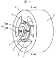
以下本発明による第1の実施の形態を図1及び図2に示す誘導電動機に基づいて説明する。一般に誘導電動機は、固定子1と、この固定子1の内周に対し周方向の空隙を介して対向する外周を有する回転子2とを備えている。
【0010】
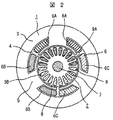
そして、固定子1は、例えば円筒状に形成した珪素鋼板を積層して形成した固定子鉄心3を有し、この固定子鉄心3の周方向に等ピッチで3つのスロット4を内径側から外径側に向かって形成し、隣接するスロット4間に歯部5を形成している。このように形成された固定子鉄心3の各歯部5に固定子巻線6を夫々集中巻きして装着し、U相固定子巻線6A,V相固定子巻線6B,W相固定子巻線6Cを形成している。
【0011】
一方、回転子2は、回転軸7上に例えば円筒状に形成した珪素鋼板を軸方向に積層して形成した回転子鉄心8と、この回転子鉄心8の外径側に、周方向等ピッチとなるように、軸方向に貫通させて装着した複数の回転子導体9と、これら複数の回転子導体9の回転子鉄心8から突出した端部を電気的に短絡させる短絡リング10とを備えている。
【0012】
本実施の形態における短絡リング10は、周方向に2分割された第1短絡リング10Aと第2短絡リング10Bとを有しており、複数の回転子導体9もこれと対応させて第1回転子導体郡9Aと第2回転子導体9Bに分けられている。そして、第1回転子導体郡9Aは第1短絡リング10Aに接続し、第2回転子導体9Bは第2短絡リング10Bに接続している。このように接続された回転子導体9と短絡リング10は、電気的に2つの回路を構成する。
【0013】
以上のように短絡リング10を周方向に2n(nは整数)分割したので、固定子1と回転子2との周方向の空隙に分布する偶数次の高調波磁束は、電気角180度ピッチで積分し平均化すると、正負の振幅で打消され、原理的にゼロとなる。即ち、回転子導体9と短絡リング10による回路が電気角180度ピッチで形成された2つの回路構成となるので、回転子導体9に鎖交する磁束は、ほぼ基本波成分のみとすることが可能となる。その結果、2分された第1回転子導体郡9Aと第2回転子導体9Bに誘導されるうず電流に含まれる偶数時高調波成分が減少し、これにより始動時発生する制動トルクを低減できるので、始動時のトルク特性を改善することができる。
【0014】
したがって、本実施の形態によれば、構造を複雑化したり、経済性を低下させることなく始動時のトルク特性を改善することができる。勿論、固定子巻線6を集中巻としたことにより、構造が簡単で経済的な誘導電動機を得ることができる。
【0015】
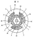
図3は、自己始動型永久磁石式同期電動機に本発明を適用した第2の実施の形態を示すもので、外観的には第1の実施の形態と同じである。
【0016】
本実施の形態において、第1の実施の形態と異なる構成は、回転子2に永久磁石11を装着した点であり、これ以外の構成は第1の実施の形態と同じである。
【0017】
即ち、本実施の形態においては、起動から加速を誘導電動機として行い、定速運転を同期電動機として行うように、回転子鉄心8の回転子導体9よりも内径側となる位置に、磁極数pが2極となるように、6つの永久磁石11を装着したのである。これら永久磁石11は、矩形断面をなし、回転子鉄心8の積層方向に沿って装着されている。
【0018】
このように短絡リング10を周方向に2n(nは整数)分割し、n≦2p(pは極数)としたことにより、第1の実施の形態と同じ効果を奏することができる。また、商用周波数の電源で運転するに際し、始動時は回転子導体9によるかご型回転子巻線により誘導電動機として同期速度直前まで駆動及び加速し、その後は同期引き入れして永久磁石11により同期電動機として運転することができるので、始動が円滑な運転を行うことができる。
【0019】
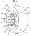
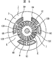
図4及び図5は、誘導電動機に本発明を適用した第3の実施の形態を示すもので、図1及び図2に示す第1の実施の形態と異なる構成は、回転子導体12と短絡リング13との接続構造である。
【0020】
即ち、本実施の形態において、短絡リング13は、周方向に2n(nは整数)分割、即ち、4分割された第1短絡リング13A,第2短絡リング13B,第3短絡リング13C,第4短絡リング13Dを用いている。同様に、複数の回転子導体12もこれと対応させて第1回転子導体郡12A,第2回転子導体郡12B,第3回転子導体郡12C,第4回転子導体12Dに分けている。そして、第1回転子導体郡12Aは第1短絡リング13Aに接続し、第2回転子導体12Bは第2短絡リング13Bに接続し、第3回転子導体郡12Cは第1短絡リング13Cに接続し、第4回転子導体12Dは第2短絡リング13Dに接続している。このように接続された回転子導体9と短絡リング10は、電気的に4つの回路を構成する。
【0021】
以上のように短絡リング12を周方向に4分割して、回転子導体12と短絡リング13による回路を4つとすることにより、回転子導体12に鎖交する偶数次の高調波磁束をさらに低減することが可能となる。その結果、4分された第1〜第4回転子導体郡12A〜12Dに夫々誘導されるうず電流に含まれる高調波成分もさらに減少し、これにより始動時発生する制動トルクをさらに低減できるので、始動時のトルク特性をさらに改善することができる。
【0022】
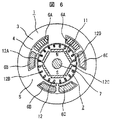
図6は、本発明を自己始動型永久磁石式同期電動機に適用した第4の実施の形態を示すもので、外観的には第3の実施の形態と同じである。
【0023】
本実施の形態において、第3の実施の形態と異なる構成は、回転子2に永久磁石11を装着した点であり、これ以外の構成は第3の実施の形態と同じである。
【0024】
本実施の形態によれば、第3の実施の形態と同じ効果を奏するほか、第2の実施の形態と同じように、始動が円滑な運転を行うことができる。
【0025】
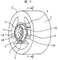
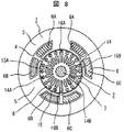
図7及び図8は、誘導電動機に本発明を適用した第5の実施の形態を示すもので、図1及び図2に示す第1の実施の形態と異なる構成は、上回転子導体14,下回転子導体15及び長断面回転子導体16A,16Bとで二重かご型回転子巻線を構成したことと、これらを短絡する第1及び第2短絡リング17,18の接続構造である。
【0026】
即ち、本実施の形態において、上回転子導体14は回転子鉄心8の外径側に周方向に等間隔に複数装着されており、下回転子導体15は上回転子導体14より内径側の回転子鉄心8に、上回転子導体14と対向するように同数装着されている。これら上及び下回転子導体14,15は、夫々第1上回転子導体郡14A,第2上回転子導体郡14B及び第1下回転子導体郡15A,第2下回転子導体郡15Bに分けられている。
【0027】
そして、長断面回転子導体16A,16Bは前記上及び下回転子導体14,15を周方向に2分する位置、云い代えれば第1上回転子導体郡14A,第1下回転子導体郡15Aと第2上回転子導体郡14B,第2下回転子導体郡15Bとの境界部となる位置の回転子鉄心8に装着されている。これら長断面回転子導体16A,16Bは、外径側が前記上回転子導体14の外径側と同じ位置となるように、内径側が前記下回転子導体15の内径側と同じ位置となるように装着されている。
【0028】
一方、これら上及び下回転子導体14,15,長断面回転子導体16A,16Bの端部を短絡する第1及び第2短絡リング17,18は、2分された上部及び下部の回転子導体14,15を交互に接続して短絡させている。即ち、第1短絡リング17の第1短絡部17Aは前記第1上回転子導体郡14Aを短絡すると共に、長断面回転子導体16Bを短絡し、さらに前記第2下回転子導体郡15Bを第2短絡部17Bで短絡している。第2短絡リング18の第1短絡部18Aは前記第2上回転子導体郡14Bを短絡すると共に、長断面回転子導体16Aを短絡し、さらに前記第1下回転子導体郡15Aを第2短絡部18Bで短絡している。
【0029】
本実施の形態によれば、第1に実施の形態と同等の効果を奏することができる。このほか、二重かご型を構成する上及び下回転子導体14,15を周方向に2分した上、第1短絡リング17及び第2短絡リング18は夫々第1上回転子導体郡14A及び第2上回転子導体郡14Bを短絡すると共に、他の短絡リング側に位置する第1下回転子導体郡15A及び第2下回転子導体郡15Bを交互に接続して短絡させているので、始動トルクを滑らかにすることができる。また、第1下回転子導体郡15A及び第2下回転子導体郡15Bは、長断面回転子導体16A,16Bを挟み込むように構成されていることから、短節ピッチで巻回されるので、上回転子導体14と下回転子導体15とに誘導電流の位相差が生じ、そのため偶数次高調波成分を低減できるとともに、奇数時高調波成分をも抑制することができる。その結果、より滑らかな回転子起磁力分布が得られ、起動トルクを滑らかにすることができる。
【0030】
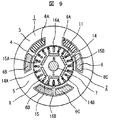
図9は、本発明を自己始動型永久磁石式同期電動機に適用した第6の実施の形態を示すもので、外観的には第5の実施の形態と同じである。
【0031】
本実施の形態において、第5の実施の形態と異なる構成は、回転子2に永久磁石11を装着した点であり、これ以外の構成は第5の実施の形態と同じである。
【0032】
本実施の形態によれば、第5の実施の形態と同じ効果を奏するほか、第2の実施の形態と同じように、始動が円滑な運転を行うことができる。
【0033】
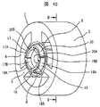
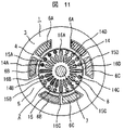
図10及び図11は、誘導電動機に本発明を適用した第7の実施の形態を示すもので、図7及び図8に示す第5の実施の形態と異なる構成は、二重かご型回転子巻線を構成する上及び下回転子導体14,15,長断面16A〜16Dを4郡に分けたことと、これらを短絡する4つの第1〜第4短絡リング17〜20の接続構造である。
【0034】
即ち、本実施の形態において、上回転子導体14は回転子鉄心8の外径側に周方向に等間隔に複数装着されており、下回転子導体15は上回転子導体14より内径側の回転子鉄心8に、上回転子導体14と対向するように複数装着されている。これら上及び下回転子導体14,15は、夫々第1上回転子導体郡14A〜第4上部回転子導体郡14D及び第1下回転子導体郡15A〜第4下部回転子導体郡15Dの4郡に分けられている。
【0035】
そして、4つの長断面回転子導体16A〜16Dは前記上及び下回転子導体14,15を周方向に4分する位置、云い代えれば第1上回転子導体郡14A,第1下回転子導体郡15Aと第4上回転子導体郡14D,第4下回転子導体郡15D間、第1上回転子導体郡14A,第1下回転子導体郡15Aと第2上回転子導体郡14B,第2下回転子導体郡15B間、第2上回転子導体郡14B,第2下回転子導体郡15Bと第3上回転子導体郡14C,第3下回転子導体郡15C間、第3上回転子導体郡14C,第3下回転子導体郡15Cと第4上回転子導体郡14D,第4下回転子導体郡15D間に位置する回転子鉄心8に装着されている。そして、これら長断面回転子導体16A〜16Dは、外径側が前記上回転子導体14の外径側と同じ位置となるように、内径側が前記回転子導体15の内径側と同じ位置となるように装着されている。
【0036】
一方、これら上及び下回転子導体14,15,長断面回転子導体16A〜16Dの端部を短絡する第1〜第4短絡リング17〜20は、4分された上及び下回転子導体14,15を巴状に交互に接続して短絡させている。即ち、第1短絡リング17の第1短絡部17Aは前記第1上回転子導体郡14Aを短絡すると共に、長断面回転子導体16Bを短絡し、さらに前記第2下回転子導体郡15Bを第2短絡部17Bで短絡している。第2短絡リング18の第1短絡部18Aは前記第2上回転子導体郡14Bを短絡すると共に、長断面回転子導体16Cを短絡し、さらに前記第3下回転子導体郡15Cを第2短絡部18Bで短絡している。第3短絡リング19の第1短絡部19Aは前記第3上回転子導体郡14Cを短絡すると共に、長断面回転子導体16Dを短絡し、さらに前記第4下回転子導体郡15Dを第2短絡部19Bで短絡している。第4短絡リング20の第1短絡部20Aは前記第4上回転子導体郡14Dを短絡すると共に、長断面回転子導体16Aを短絡し、さらに前記第1下回転子導体郡15Aを第2短絡部20Bで短絡している。
【0037】
本実施の形態によれば、上記第5の実施の形態と同じ効果を奏するほか、回転子導体を4郡に分け、電気角で略180度ピッチで巻回されるような4つの短絡リングで巴状に短絡したので、短絡リングを2分割した場合に比べ偶数次高調波成分をより大きく低減でき、トルク特性をさらに改善することができる。
【0038】
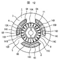
図12は、本発明を自己始動型永久磁石式同期電動機に適用した第8の実施の形態を示すもので、外観的には第7の実施の形態と同じである。
【0039】
本実施の形態において、第7の実施の形態と異なる構成は、回転子2に永久磁石11を装着した点であり、これ以外の構成は第7の実施の形態と同じである。
【0040】
本実施の形態によれば、第7の実施の形態と同じ効果を奏するほか、第2の実施の形態と同じように、始動が円滑な運転を行うことができる。
【0041】
次に、上記のように構成された駆動用電動機を圧縮機に適用した一例を図13に基づいて説明する。ここに用いた駆動用電動機は、例えば、図3に示す第2の実施の形態による永久磁石式同期電動機を用いた。したがって、図3と同一符号は同一部品を示すので、永久磁石式同期電動機の再度の詳細な説明は省略する。
【0042】
圧縮機21は、円筒状の密封圧力容器22と、この密封圧力容器22内に設置され駆動用電動機となる自己始動型の永久磁石式同期電動機23と、この永久磁石式同期電動機23により駆動され前記密封圧力容器22内に設置される圧縮機構部24とを備えている。
【0043】
永久磁石式同期電動機23は、密封圧力容器22内に軸受25A,25Bを介して回転自在に支承された回転軸7に固定された回転子2と、この回転子2に周方向の空隙を介して対向し密封圧力容器22内固定された固定子1とを備えている。
【0044】
このように構成された永久磁石式同期電動機23を駆動用電動機として用いた圧縮機21の圧縮機構部24は、回転軸7の上端に形成されたクランク軸26によって旋回する旋回スクロール部材27と、この旋回スクロール部材27と噛合う固定スクロール部材28とを備えている。そして、前記旋回スクロール部材27は、端板29に直立する可動渦巻状ラップ30を有し、前記固定スクロール部材28は、可動渦巻状ラップ30と噛合う固定渦巻状ラップ31と、この固定渦巻状ラップ31を直立支持する端板32を有する。
【0045】
このように構成された圧縮機構部24の可動渦巻状ラップ30をクランク軸26によって旋回運動させると、可動渦巻状ラップ30と固定渦巻状ラップ31とによって形成された圧縮室33Aが外径側から中心に向かって移動する過程で次第に容積を縮小し、圧縮動作を行うのである。
【0046】
前記密封圧力容器22内の底部には、潤滑油37が満たされており、この潤滑油37内に前記回転軸7の下端を浸している。この回転軸7にはクランク軸26まで貫通する油孔38が設けられており、回転軸7の回転時の圧力差を利用して、前記潤滑油37を旋回スクロール部材27とクランク軸26間及び軸受25Aへ給油している。
【0047】
以上のように構成した圧縮機21は、運転を開始すると、ガス供給口34から供給されたガスを外径側に位置する圧縮室33Aに供給する。この圧縮室33Aに供給されたガスは中心側の圧縮室30Bに至る間に圧縮され、この圧縮室30Bに設けた吐出口35から密封圧力容器22内に吐出される。吐出された圧縮ガスは、圧縮機構部24と永久磁石式同期電動機23の間に廻り込み、ここの密封圧力容器22の側壁に設けた吐出パイプ36から圧縮機1外に排出される。
【0048】
このように本発明による駆動用電動機を圧縮機に適用することにより、一定速圧縮機の高効率化を容易に得ることができる。
【0049】
尚、一例として第2の実施の形態による永久磁石式同期電動機を圧縮機に適用したが、これに限らず他の実施の形態による誘導電動機や永久磁石式同期電動機を用いることができることは云うまでもない。
【0050】
【発明の効果】
以上説明したように本発明によれば、構造の複雑化や経済性を低下させることなく始動時のトルク特性を改善できる駆動用電動機及びこれを用いた圧縮機を得ることができる。
【図面の簡単な説明】
【図1】本発明による駆動用電動機の第1の実施の形態として誘導電動機を示す概略斜視図。
【図2】図1のA―A線に沿う断面図。
【図3】本発明による駆動用電動機の第2の実施の形態として自己始動型永久磁石式同期電動機を示す図2相当図。
【図4】本発明による駆動用電動機の第3の実施の形態として誘導電動機を示す概略斜視図。
【図5】図4のB―B線に沿う断面図。
【図6】本発明による駆動用電動機の第4の実施の形態として自己始動型永久磁石式同期電動機を示す図5相当図。
【図7】本発明による駆動用電動機の第5の実施の形態として誘導電動機を示す概略斜視図。
【図8】図7のC―C線に沿う断面図。
【図9】本発明による駆動用電動機の第6の実施の形態として自己始動型永久磁石式同期電動機を示す図8相当図。
【図10】本発明による駆動用電動機の第7の実施の形態として誘導電動機を示す概略斜視図。
【図11】図10のD―D線に沿う断面図。
【図12】本発明による駆動用電動機の第8の実施の形態として自己始動型永久磁石式同期電動機を示す図11相当図。
【図13】本発明による駆動用電動機を適用した圧縮機を示す概略縦断面図。
【符号の説明】
1…固定子、2…回転子、3…固定子鉄心、5…歯部、6…固定子巻線、8…回転子鉄心、9,12…回転子導体、14…上回転子導体、15…下回転子導体、16A〜16D…長断面回転子導体、10,13,17〜20…短絡リング、11…永久磁石、21…圧縮機、23…駆動用電動機、24…圧縮機構部。[0001]
TECHNICAL FIELD OF THE INVENTION
The present invention relates to a drive motor and a compressor using the same, and more particularly, to a drive motor such as an induction motor or a self-starting permanent magnet synchronous motor having a stator having a concentratedly wound stator winding on the stator, and a drive motor therefor. And a compressor using the same.
[0002]
[Prior art]
2. Description of the Related Art Conventionally, as a driving motor having a simple structure and economical, as disclosed in Patent Documents 1 and 2, for example, an induction motor having a stator winding concentratedly wound around a stator or a self-starting type is disclosed. Permanent magnet type synchronous motors are known.
[0003]
[Patent Document 1]
JP 2001-204161 A [Patent Document 2]
JP 2001-157427 A
[Problems to be solved by the invention]
According to the above-described conventional technology, a small-sized driving motor having a simple structure and being economical can be obtained. However, in the induction motor, since the stator windings are concentratedly wound, the harmonic magnetic flux mainly composed of even-order harmonics such as the second and fourth harmonics increases. As a result, there is a concern that torque characteristics at the time of starting the induction motor may be deteriorated due to the harmonic magnetic flux. For this reason, various measures have been taken to reduce the harmonic magnetic flux, but they unnecessarily complicate the structure or reduce the economic efficiency.
[0005]
On the other hand, the concentrated winding of the stator winding causes the self-starting permanent magnet type synchronous motor to operate as an induction motor at the time of starting, so that even-order harmonic magnetic flux generates abnormal torque at the time of starting. Various measures have been taken to alleviate the abnormal torque, but as a result, as in the case of the induction motor, the structure is complicated and the economy is reduced.
[0006]
An object of the present invention is to provide a driving motor that can improve torque characteristics at the time of starting without complicating the structure and reducing economic efficiency.
[0007]
[Means for Solving the Problems]
In order to achieve the above object, the present invention provides a driving motor including a stator winding having a concentrated winding around a stator core and a rotor conductor provided on a rotor core, wherein a short-circuit ring for short-circuiting the rotor conductor is provided. It is divided into 2n (n is an integer) in the circumferential direction.
[0008]
By providing the concentrated winding stator winding and the rotor conductor among the above-described configurations, it is possible to obtain an economical driving motor having a simple structure. Further, by dividing the short-circuit ring for short-circuiting the rotor conductor into an even number in the circumferential direction, even-order harmonic magnetic flux linked to the conductor of the rotor conductor is reduced, so that it is included in the eddy current induced in the conductor. Harmonic components can also be reduced, and as a result, the generation of braking torque can be suppressed and the torque characteristics at the time of starting can be improved.
[0009]
BEST MODE FOR CARRYING OUT THE INVENTION
Hereinafter, a first embodiment according to the present invention will be described based on an induction motor shown in FIGS. In general, an induction motor includes a stator 1 and a rotor 2 having an outer periphery opposed to an inner periphery of the stator 1 via a circumferential gap.
[0010]
The stator 1 has, for example, a stator core 3 formed by laminating silicon steel sheets formed in a cylindrical shape. Three slots 4 are formed at equal pitches in the circumferential direction of the stator core 3 from the inner side. The teeth 5 are formed between the adjacent slots 4. The stator windings 6 are concentratedly wound around the respective tooth portions 5 of the stator core 3 formed as described above, and are attached to the stator windings 6A, V-phase stator windings 6B, and W-phase stators. The winding 6C is formed.
[0011]
On the other hand, the rotor 2 includes a rotor core 8 formed by axially laminating, for example, a silicon steel plate formed in a cylindrical shape on a rotation shaft 7, and an outer circumferential side of the rotor core 8 having a uniform pitch in a circumferential direction. And a short-circuit ring 10 for electrically short-circuiting the ends of the plurality of rotor conductors 9 protruding from the rotor core 8 so as to be electrically mounted. ing.
[0012]
The short-circuit ring 10 in the present embodiment has a first short-circuit ring 10A and a second short-circuit ring 10B which are divided into two in the circumferential direction, and the plurality of rotor conductors 9 also correspond to the first short-circuit ring. It is divided into child conductor group 9A and second rotor conductor 9B. The first rotor conductor group 9A is connected to the first short-circuit ring 10A, and the second rotor conductor 9B is connected to the second short-circuit ring 10B. The rotor conductor 9 and the short-circuit ring 10 connected in this way electrically constitute two circuits.
[0013]
Since the short-circuit ring 10 is divided into 2n (n is an integer) in the circumferential direction as described above, the even-order harmonic magnetic flux distributed in the circumferential gap between the stator 1 and the rotor 2 has an electrical angle of 180 degrees pitch. Integrating with and averaging cancels out with positive and negative amplitudes, and becomes zero in principle. That is, since the circuit composed of the rotor conductor 9 and the short-circuit ring 10 has two circuit configurations formed at a pitch of 180 electrical degrees, the magnetic flux linked to the rotor conductor 9 may be substantially only a fundamental wave component. It becomes possible. As a result, even-number harmonic components contained in the eddy currents induced in the first rotor conductor group 9A and the second rotor conductor 9B, which are divided into two, are reduced, so that the braking torque generated at the time of starting can be reduced. Therefore, the torque characteristics at the time of starting can be improved.
[0014]
Therefore, according to the present embodiment, the torque characteristics at the time of starting can be improved without complicating the structure or reducing the economic efficiency. Of course, since the stator windings 6 are concentratedly wound, an economical induction motor having a simple structure can be obtained.
[0015]
FIG. 3 shows a second embodiment in which the present invention is applied to a self-starting permanent magnet type synchronous motor. The appearance is the same as that of the first embodiment.
[0016]
In the present embodiment, a configuration different from the first embodiment is that a permanent magnet 11 is mounted on the rotor 2, and the other configuration is the same as the first embodiment.
[0017]
That is, in the present embodiment, the number of magnetic poles p is set at a position closer to the inner diameter side of the rotor conductor 9 of the rotor core 8 so that acceleration from start-up is performed as an induction motor and constant-speed operation is performed as a synchronous motor. The six permanent magnets 11 are mounted such that the poles have two poles. These permanent magnets 11 have a rectangular cross section and are mounted along the lamination direction of the rotor core 8.
[0018]
As described above, by dividing the short-circuit ring 10 in the circumferential direction by 2n (n is an integer) and n ≦ 2p (p is the number of poles), the same effect as in the first embodiment can be obtained. In addition, when operating with a commercial frequency power supply, at the time of starting, the induction motor is driven and accelerated by a squirrel-cage rotor winding by the rotor conductor 9 until just before the synchronous speed. The operation can be smoothly performed.
[0019]
4 and 5 show a third embodiment in which the present invention is applied to an induction motor. The configuration different from that of the first embodiment shown in FIGS. This is a connection structure with the ring 13.
[0020]
That is, in the present embodiment, the short-circuit ring 13 is divided into 2n (n is an integer) in the circumferential direction, that is, the first short-circuit ring 13A, the second short-circuit ring 13B, the third short-circuit ring 13C, and the fourth short-circuit ring 13 are divided into four. The short-circuit ring 13D is used. Similarly, the plurality of rotor conductors 12 are also correspondingly divided into a first rotor conductor group 12A, a second rotor conductor group 12B, a third rotor conductor group 12C, and a fourth rotor conductor 12D. The first rotor conductor group 12A is connected to the first short-circuit ring 13A, the second rotor conductor 12B is connected to the second short-circuit ring 13B, and the third rotor conductor group 12C is connected to the first short-circuit ring 13C. The fourth rotor conductor 12D is connected to the second short-circuit ring 13D. The rotor conductor 9 and the short-circuit ring 10 connected in this manner electrically constitute four circuits.
[0021]
As described above, the short-circuit ring 12 is divided into four parts in the circumferential direction, and four circuits are formed by the rotor conductor 12 and the short-circuit ring 13, thereby further reducing even-order harmonic magnetic flux interlinking the rotor conductor 12. It is possible to do. As a result, the harmonic components included in the eddy currents induced in the four divided first to fourth rotor conductor groups 12A to 12D are further reduced, so that the braking torque generated at the time of starting can be further reduced. In addition, the torque characteristics at the time of starting can be further improved.
[0022]
FIG. 6 shows a fourth embodiment in which the present invention is applied to a self-starting permanent magnet type synchronous motor, and is the same in appearance as the third embodiment.
[0023]
In the present embodiment, the configuration different from the third embodiment is that a permanent magnet 11 is mounted on the rotor 2, and the other configuration is the same as the third embodiment.
[0024]
According to the present embodiment, in addition to the same effects as in the third embodiment, the operation can be smoothly started as in the second embodiment.
[0025]
7 and 8 show a fifth embodiment in which the present invention is applied to an induction motor. The configuration different from that of the first embodiment shown in FIGS. This is a double-cage rotor winding constituted by the lower rotor conductor 15 and the long-section rotor conductors 16A and 16B, and a connection structure of first and second short-circuit rings 17 and 18 for short-circuiting these.
[0026]
That is, in the present embodiment, a plurality of upper rotor conductors 14 are mounted on the outer diameter side of the rotor core 8 at equal intervals in the circumferential direction, and the lower rotor conductor 15 is located on the inner diameter side of the upper rotor conductor 14. The same number is mounted on the rotor core 8 so as to face the upper rotor conductor 14. The upper and lower rotor conductors 14, 15 are divided into a first upper rotor conductor group 14A, a second upper rotor conductor group 14B, a first lower rotor conductor group 15A, and a second lower rotor conductor group 15B, respectively. Have been.
[0027]
The long-section rotor conductors 16A and 16B divide the upper and lower rotor conductors 14 and 15 in the circumferential direction, that is, the first upper rotor conductor group 14A and the first lower rotor conductor group 15A. And the second upper rotor conductor group 14B and the second lower rotor conductor group 15B. These long-section rotor conductors 16A and 16B are arranged such that the outer diameter side is at the same position as the outer diameter side of the upper rotor conductor 14, and the inner diameter side is at the same position as the inner diameter side of the lower rotor conductor 15. It is installed.
[0028]
On the other hand, the first and second short-circuit rings 17, 18 for short-circuiting the ends of the upper and lower rotor conductors 14, 15 and the long-section rotor conductors 16A, 16B are divided into upper and lower rotor conductors. 14 and 15 are connected alternately and short-circuited. That is, the first short-circuit portion 17A of the first short-circuit ring 17 short-circuits the first upper rotor conductor group 14A, short-circuits the long-section rotor conductor 16B, and further connects the second lower rotor conductor group 15B. The two short-circuit portions 17B are short-circuited. The first short-circuit portion 18A of the second short-circuit ring 18 short-circuits the second upper rotor conductor group 14B, short-circuits the long-section rotor conductor 16A, and further short-circuits the first lower rotor conductor group 15A. There is a short circuit at the portion 18B.
[0029]
According to the present embodiment, the same effects as those of the first embodiment can be obtained. In addition, the upper and lower rotor conductors 14 and 15 constituting the double cage are divided into two in the circumferential direction, and the first short-circuit ring 17 and the second short-circuit ring 18 are respectively connected to the first upper rotor conductor group 14A and Since the second upper rotor conductor group 14B is short-circuited and the first lower rotor conductor group 15A and the second lower rotor conductor group 15B located on the other short-circuit ring side are alternately connected and short-circuited. The starting torque can be made smooth. Since the first lower rotor conductor group 15A and the second lower rotor conductor group 15B are configured to sandwich the long-section rotor conductors 16A and 16B, they are wound at a short pitch. A phase difference of the induced current occurs between the upper rotor conductor 14 and the lower rotor conductor 15, so that even-order harmonic components can be reduced and odd-number harmonic components can be suppressed. As a result, a smoother rotor magnetomotive force distribution is obtained, and the starting torque can be smoothed.
[0030]
FIG. 9 shows a sixth embodiment in which the present invention is applied to a self-starting permanent magnet type synchronous motor, and is externally the same as the fifth embodiment.
[0031]
In the present embodiment, the configuration different from the fifth embodiment is that a permanent magnet 11 is mounted on the rotor 2, and the other configuration is the same as the fifth embodiment.
[0032]
According to the present embodiment, in addition to the same effects as in the fifth embodiment, the operation can be smoothly started as in the second embodiment.
[0033]
FIGS. 10 and 11 show a seventh embodiment in which the present invention is applied to an induction motor. The configuration different from the fifth embodiment shown in FIGS. 7 and 8 is a double-cage rotor. The upper and lower rotor conductors 14 and 15 and the long sections 16A to 16D constituting the winding are divided into four groups, and a connection structure of four first to fourth short-circuit rings 17 to 20 for short-circuiting these groups. .
[0034]
That is, in the present embodiment, a plurality of upper rotor conductors 14 are mounted on the outer diameter side of the rotor core 8 at equal intervals in the circumferential direction, and the lower rotor conductor 15 is located on the inner diameter side of the upper rotor conductor 14. A plurality of rotor cores 8 are mounted so as to face the upper rotor conductor 14. These upper and lower rotor conductors 14 and 15 are respectively composed of a first upper rotor conductor group 14A to a fourth upper rotor conductor group 14D and a first lower rotor conductor group 15A to a fourth lower rotor conductor group 15D. It is divided into counties.
[0035]
The four long-section rotor conductors 16A to 16D are located at positions dividing the upper and lower rotor conductors 14 and 15 in the circumferential direction, in other words, the first upper rotor conductor group 14A and the first lower rotor conductor. Between the group 15A and the fourth upper rotor conductor group 14D, between the fourth lower rotor conductor group 15D, the first upper rotor conductor group 14A, the first lower rotor conductor group 15A and the second upper rotor conductor group 14B, Second lower rotor conductor group 15B, second upper rotor conductor group 14B, second lower rotor conductor group 15B and third upper rotor conductor group 14C, third lower rotor conductor group 15C, third upper rotation The rotor core 8 is mounted between the child conductor group 14C, the third lower rotor conductor group 15C, the fourth upper rotor conductor group 14D, and the fourth lower rotor conductor group 15D. These long-section rotor conductors 16A to 16D are arranged such that the outer diameter side is the same as the outer diameter side of the upper rotor conductor 14 and the inner diameter side is the same as the inner diameter side of the rotor conductor 15. It is attached to.
[0036]
On the other hand, the first to fourth short-circuiting rings 17 to 20 for short-circuiting the ends of the upper and lower rotor conductors 14 and 15 and the long-section rotor conductors 16A to 16D are divided into four upper and lower rotor conductors 14. , 15 are connected alternately in a tom-like fashion to short-circuit. That is, the first short-circuit portion 17A of the first short-circuit ring 17 short-circuits the first upper rotor conductor group 14A, short-circuits the long-section rotor conductor 16B, and further connects the second lower rotor conductor group 15B. The two short-circuit portions 17B are short-circuited. The first short-circuit portion 18A of the second short-circuit ring 18 short-circuits the second upper rotor conductor group 14B, short-circuits the long-section rotor conductor 16C, and further short-circuits the third lower rotor conductor group 15C. There is a short circuit at the portion 18B. The first short-circuit portion 19A of the third short-circuit ring 19 short-circuits the third upper rotor conductor group 14C, short-circuits the long-section rotor conductor 16D, and further short-circuits the fourth lower rotor conductor group 15D. There is a short circuit at the portion 19B. The first short-circuit portion 20A of the fourth short-circuit ring 20 short-circuits the fourth upper rotor conductor group 14D, short-circuits the long-section rotor conductor 16A, and further short-circuits the first lower rotor conductor group 15A. There is a short circuit at the part 20B.
[0037]
According to the present embodiment, in addition to the same effects as in the above fifth embodiment, the rotor conductor is divided into four groups, and four short-circuit rings wound at a pitch of about 180 degrees in electrical angle are used. Since the short-circuit has been short-circuited, even-order harmonic components can be further reduced as compared with the case where the short-circuit ring is divided into two, and the torque characteristics can be further improved.
[0038]
FIG. 12 shows an eighth embodiment in which the present invention is applied to a self-starting permanent magnet synchronous motor, and is the same in appearance as the seventh embodiment.
[0039]
This embodiment is different from the seventh embodiment in that a permanent magnet 11 is mounted on the rotor 2, and the other configuration is the same as the seventh embodiment.
[0040]
According to the present embodiment, the same effects as in the seventh embodiment can be obtained, and in addition, as in the second embodiment, the operation can be smoothly started.
[0041]
Next, an example in which the drive motor configured as described above is applied to a compressor will be described with reference to FIG. As the driving motor used here, for example, a permanent magnet synchronous motor according to the second embodiment shown in FIG. 3 was used. Therefore, the same reference numerals as those in FIG. 3 denote the same parts, and a detailed description of the permanent magnet type synchronous motor will not be repeated.
[0042]
The compressor 21 is driven by the cylindrical sealed pressure vessel 22, a self-starting permanent magnet synchronous motor 23 installed in the sealed pressure vessel 22 and serving as a driving motor, and the permanent magnet synchronous motor 23. And a compression mechanism 24 installed in the sealed pressure vessel 22.
[0043]
The permanent magnet type synchronous motor 23 includes a rotor 2 fixed to a rotating shaft 7 rotatably supported in a sealed pressure vessel 22 via bearings 25A and 25B, and a circumferential gap formed between the rotor 2 and the rotor 2. And a stator 1 opposed to and fixed in the sealed pressure vessel 22.
[0044]
A compression mechanism section 24 of the compressor 21 using the permanent magnet type synchronous motor 23 configured as described above as a drive motor includes a orbiting scroll member 27 that orbits by a crankshaft 26 formed at an upper end of the rotating shaft 7, A fixed scroll member 28 that meshes with the orbiting scroll member 27 is provided. The orbiting scroll member 27 has a movable spiral wrap 30 standing upright on an end plate 29, and the fixed scroll member 28 has a fixed spiral wrap 31 meshed with the movable spiral wrap 30 and a fixed spiral wrap 31. It has an end plate 32 that supports the wrap 31 upright.
[0045]
When the movable spiral wrap 30 of the compression mechanism unit 24 having the above-described configuration is swirled by the crankshaft 26, the compression chamber 33A formed by the movable spiral wrap 30 and the fixed spiral wrap 31 is moved from the outer diameter side. In the process of moving toward the center, the volume is gradually reduced, and the compression operation is performed.
[0046]
The bottom of the sealed pressure vessel 22 is filled with a lubricating oil 37, and the lower end of the rotating shaft 7 is immersed in the lubricating oil 37. The rotary shaft 7 is provided with an oil hole 38 penetrating to the crankshaft 26, and the lubricating oil 37 is supplied between the orbiting scroll member 27 and the crankshaft 26 by utilizing a pressure difference when the rotary shaft 7 rotates. Oil is supplied to the bearing 25A.
[0047]
When the compressor 21 configured as described above starts operating, it supplies the gas supplied from the gas supply port 34 to the compression chamber 33A located on the outer diameter side. The gas supplied to the compression chamber 33A is compressed while reaching the compression chamber 30B on the center side, and is discharged into the sealed pressure vessel 22 from a discharge port 35 provided in the compression chamber 30B. The discharged compressed gas flows between the compression mechanism 24 and the permanent magnet type synchronous motor 23 and is discharged out of the compressor 1 from a discharge pipe 36 provided on a side wall of the sealed pressure vessel 22.
[0048]
By applying the drive motor according to the present invention to a compressor in this manner, it is possible to easily obtain a high-efficiency constant-speed compressor.
[0049]
The permanent magnet synchronous motor according to the second embodiment is applied to a compressor as an example. However, the present invention is not limited to this, and it is needless to say that an induction motor or a permanent magnet synchronous motor according to another embodiment can be used. Nor.
[0050]
【The invention's effect】
As described above, according to the present invention, it is possible to obtain a driving motor and a compressor using the same, which can improve the torque characteristics at the time of starting without complicating the structure and reducing the economic efficiency.
[Brief description of the drawings]
FIG. 1 is a schematic perspective view showing an induction motor as a first embodiment of a driving motor according to the present invention.
FIG. 2 is a sectional view taken along the line AA of FIG. 1;
FIG. 3 is a diagram corresponding to FIG. 2 showing a self-starting permanent magnet type synchronous motor as a second embodiment of the driving motor according to the present invention.
FIG. 4 is a schematic perspective view showing an induction motor as a third embodiment of the driving motor according to the present invention.
FIG. 5 is a sectional view taken along the line BB in FIG. 4;
FIG. 6 is a diagram corresponding to FIG. 5 showing a self-starting permanent magnet type synchronous motor as a fourth embodiment of the driving motor according to the present invention.
FIG. 7 is a schematic perspective view showing an induction motor as a driving motor according to a fifth embodiment of the present invention.
FIG. 8 is a sectional view taken along the line CC of FIG. 7;
FIG. 9 is a diagram corresponding to FIG. 8 showing a self-starting permanent magnet type synchronous motor as a sixth embodiment of the driving motor according to the present invention.
FIG. 10 is a schematic perspective view showing an induction motor as a driving motor according to a seventh embodiment of the present invention.
FIG. 11 is a sectional view taken along the line DD in FIG. 10;
FIG. 12 is a diagram corresponding to FIG. 11 showing a self-starting permanent magnet type synchronous motor as an eighth embodiment of the driving motor according to the present invention.
FIG. 13 is a schematic longitudinal sectional view showing a compressor to which the driving motor according to the present invention is applied.
[Explanation of symbols]
DESCRIPTION OF SYMBOLS 1 ... stator, 2 ... rotor, 3 ... stator core, 5 ... tooth part, 6 ... stator winding, 8 ... rotor core, 9, 12 ... rotor conductor, 14 ... upper rotor conductor, 15 ... Lower rotor conductors, 16A to 16D long rotor conductors, 10, 13, 17 to 20 short-circuit rings, 11 permanent magnets, 21 compressor, 23 motor for driving, 24 compression mechanism.