JP2004302829A - Power switch circuit of on-vehicle information terminal, and on-vehicle information terminal - Google Patents
Power switch circuit of on-vehicle information terminal, and on-vehicle information terminal Download PDFInfo
- Publication number
- JP2004302829A JP2004302829A JP2003094712A JP2003094712A JP2004302829A JP 2004302829 A JP2004302829 A JP 2004302829A JP 2003094712 A JP2003094712 A JP 2003094712A JP 2003094712 A JP2003094712 A JP 2003094712A JP 2004302829 A JP2004302829 A JP 2004302829A
- Authority
- JP
- Japan
- Prior art keywords
- power supply
- voltage
- microcomputer
- backup power
- information terminal
- Prior art date
- Legal status (The legal status is an assumption and is not a legal conclusion. Google has not performed a legal analysis and makes no representation as to the accuracy of the status listed.)
- Pending
Links
- 230000007423 decrease Effects 0.000 description 7
- 238000001514 detection method Methods 0.000 description 6
- 238000010586 diagram Methods 0.000 description 3
- 230000000694 effects Effects 0.000 description 2
- 230000006870 function Effects 0.000 description 2
- 230000004044 response Effects 0.000 description 2
- 230000001771 impaired effect Effects 0.000 description 1
- 230000002093 peripheral effect Effects 0.000 description 1
- 230000001360 synchronised effect Effects 0.000 description 1
Images

Landscapes
- Power Sources (AREA)
- Stand-By Power Supply Arrangements (AREA)
- Direct Current Feeding And Distribution (AREA)
Abstract
Description
【0001】
【発明の属する技術分野】
本発明は、ナビゲーション装置などの車載用情報端末において、供給される主電源の電圧が低下したときにバックアップ用電源に切り換える車載用情報端末の電源切り換え回路に関する。
【0002】
【従来の技術】
通常、ナビゲーション装置などの車載用情報端末は、車載バッテリより供給される電源によって動作する。そのため、車両のイグニッションスイッチをオフしたときやバッテリが放電した状態などでは、供給される電源の電圧が低下して動作できなくなる。特に、揮発性の記憶装置に情報を記憶する車載用情報端末、たとえば、配信された地図データなどの各種情報をマイコン内のRAMに記憶する通信ナビゲーション装置などでは、この電源電圧の低下によって記憶した情報が消えてしまうことがある。このようなことを避けるため、電源電圧が低下したときにバックアップ電源に切り換える機能を有するマイコンを備えた車載用情報端末がある。
【0003】
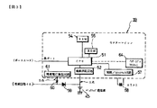
このような電源の切り換え機能を有するマイコンとしては、たとえば、特許文献1のマイコン装置が知られている。このマイコン装置は図3に示す構成を有しており、電源回路40およびバックアップ用電源45がともに電源供給回路52へ接続されている。これにより、通常使用している電源回路40の電圧が低下した場合には、代わりにバックアップ用電源45から電源供給回路52へ電源が供給される。また、電源回路40の電圧を電源電圧検出回路61により検出し、これが所定電圧以下になった場合、CPU51をスリープモードに設定して、消費電力を低減する。特許文献1のマイコン装置によれば、電源回路40からバックアップ用電源45への切り換えと、CPU51のスリープモード設定を同期させることで、電源電圧が低下した状態でもしばらくの間記憶情報の消失を避けることができる。なお、車載用情報端末において、図3の電源回路40は車載バッテリに相当し、バックアップ用電源45はバックアップ用電池などに相当する。
【0004】
【特許文献1】
特開平07−271754号公報
【0005】
特許文献1のマイコン装置では、電源回路40の出力はダイオード59を介して図のA点へ出力され、その電圧がバックアップ用電源45の電圧より低い場合に、バックアップ用電源45と切り換えられる。また、電源回路40の出力はダイオード60を介して電源電圧検出回路61へも出力され、その電圧が所定値以下となった場合に、CPU51がスリープモードに設定される。そのため、ダイオード59と60の特性のばらつきによって、バックアップ用電源45への切り換えを行う電源電圧と、スリープモードの設定を行う電源電圧とが一致せず、これらが同期しないことがある。この場合、CPU51がスリープモードに設定されずにバックアップ用電源45より電源が供給されている状態となり、バックアップ用電源45がすぐに消費されてしまうことがある。
【0006】
本発明は、供給される主電源の電圧が低下したときに、部品特性に影響されることなく、消費電力の低減とバックアップ用電源への切り換えが同期して行われるようにする車載用情報端末の電源切り換え回路を提供するものである。
【0007】
【課題を解決するための手段】
請求項1の発明による車載用情報端末の電源切り換え回路は、外部の主電源供給手段より主電源を入力する主電源入力端子と、外部のバックアップ電源供給手段よりバックアップ電源を入力するバックアップ電源入力端子と、入力された主電源またはバックアップ電源のいずれかを選択して外部へ供給する電源供給手段と、入力された主電源の電圧が所定電圧以下となったときに信号を出力する信号出力手段と、その信号を外部へ出力するリセット手段とを備え、電源供給手段は、信号出力手段から信号が出力された場合、外部へ供給する電源を主電源からバックアップ電源に切り換えることとするものである。
請求項2の発明による車載用情報端末は、請求項1の電源切り換え回路と、電源切り換え回路にバックアップ電源を出力するバックアップ電源供給手段と、電源切り換え回路より電源を供給されるマイコン装置とを備え、マイコン装置は、電源切り換え回路から信号が出力された場合、自身をスリープモードに設定することとするものである。
請求項3の発明は、請求項2の車載用情報端末において適用され、バックアップ電源供給手段は、一次電池により構成されることとするものである。
【0008】
【発明の実施の形態】
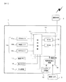
本発明による車載用情報端末の一実施例であるナビゲーション装置を図1に示す。図1のナビゲーション装置1は、情報配信センターから送信される地図データなどの各種情報を通信端末2により受信し、ユーザへ提供する。このナビゲーション装置1は、車載バッテリ3より供給される電源によって通常は動作しており、その電圧が低下すると、電源の供給元をバックアップ用電源15に切り換える。ナビゲーション装置1は、マイコン10、電源切り換え回路14、バックアップ用電源15、現在地検出装置16、画像メモリ17、表示モニタ18および入力装置19を有している。
【0009】
マイコン10は、制御回路11、ROM12およびRAM13を有している。制御回路11は、マイクロプロセッサおよびその周辺回路からなり、RAM13を作業エリアとしてROM12に格納された制御プログラムを実行して各種の制御を行う。なお、通信端末2により受信した地図データなどの各種情報は、RAM13に記憶される。このRAM13は、マイコン10に電源が供給されているときのみ、その情報を記憶することができる。すなわち、マイコン10に電源が供給されなくなると、RAM13に記憶されていた情報は消失する。
【0010】
電源切り換え回路14は、バックアップ用電源15および車載バッテリ3より供給される電源のいずれかを選択して、どちらか一方の電源をマイコン10に供給する。このとき、通常の状態では車載バッテリ3からの電源を供給し、車載バッテリ3からの電源電圧が低下した場合、すなわち、車両のイグニッションスイッチをオフされた場合やバッテリの放電が進んだ場合などには、バックアップ用電源15からの電源を供給する。この電源切り換え回路14の動作の詳細については、後に説明する。なお、バックアップ用電源15には、たとえば、アルカリ電池などの一次電池が用いられる。
【0011】
また、電源切り換え回路14は、マイコン10へ供給する電源を車載バッテリ3からバックアップ用電源15に切り換えるとき、マイコン10へリセット信号を出力する。マイコン10は、このリセット信号が出力されると自身をスリープモードに設定する。スリープモードに設定されると、マイコン10は外部からの入力を受け付けなくして、RAM13に記憶された情報を保持するために必要な最小限の処理のみを実行し、自身の消費電力を低減する。車載バッテリ3からの電源電圧が回復すると、電源切り換え回路14は、マイコン10へ供給する電源をバックアップ用電源15から車載バッテリ3に戻し、リセット解除信号を出力する。このリセット解除信号を受けると、マイコン10はスリープモードの設定を解除する。
【0012】
現在地検出装置16は車両の現在地を検出する装置であり、たとえば、車両の進行方位を検出する方位センサ16a、車速を検出する車速センサ16b、GPS衛星からのGPS信号を検出するGPSセンサ16c等からなる。ナビゲーション装置1は、この現在地検出装置16により検出された車両の現在地を含んだ地域の地図を、通信端末2を介して図示しない情報配信センターへ要求する。さらに、その要求を受けて情報配信センターより送信された地図データ上に、現在地検出装置16により検出された車両の現在地、すなわち自車位置を示して、表示モニタ18に表示する。
【0013】
画像メモリ17は、表示モニタ18に表示するための画像データを格納する。この画像データは道路地図描画用データや各種の図形データ等からなり、それらは情報配信センターから送信される地図データに基づいて適宜選択される。ナビゲーション装置1は、この選択された画像データを表示モニタ18に表示することにより、送信された地図データの情報をユーザへ提供することができる。
【0014】
入力装置19は、車両の目的地等を入力する各種スイッチを有する。この入力装置19により車両の目的地を入力すると、ナビゲーション装置1は、現在地検出装置16により検出された車両の現在地からその目的地までの地図データを、情報配信センターへ要求する。この要求により地図情報配信センターから送信された地図データは、前述のように通信端末2により受信され、RAM13に記憶される。
【0015】
電源切り換え回路14の回路例を図2に示す。電源切り換え回路14は、リセットIC21、トランジスタQ1およびQ2、抵抗R1およびR2、およびダイオードD1を有している。また、端子22には車載バッテリ3からの主電源、端子23にはバックアップ用電源15からのバックアップ電源が入力され、どちらか一方を選択して、端子24よりマイコン10へ出力する。このとき、端子22に入力される主電源はトランジスタQ1を介してマイコン10に出力され、端子23に入力されるバックアップ電源はダイオードD1を介してマイコン10に出力される。この電源の切り換えは、リセットIC21により次に説明するようにして制御される。
【0016】
リセットIC21は、端子22に入力される車載バッテリ3からの主電源の電圧を監視し、この主電源電圧が所定電圧以下になると、リセットIC21はその出力電圧をH(ハイ)からL(ロー)へ変化する。この出力は、抵抗R2を介してトランジスタQ2のB(ベース)へ接続されており、HからLへ変化することにより、トランジスタQ2がオフとなる。すると、このトランジスタQ2のC(コレクタ)へ接続されたトランジスタQ1がオフとなり、車載バッテリ3からの主電源がマイコン10へ出力されなくなる。このとき、端子23に入力されるバックアップ電源がダイオードD1を介して出力される。
【0017】
その後、主電源電圧が所定電圧より大きい電圧に回復すると、リセットIC21はその出力電圧をLからHへ変化する。すると、トランジスタQ2がオンとなり、これによりトランジスタQ1がオンとなって、端子22に入力される主電源がマイコン10へ出力される。このとき、点Pにおいてバックアップ電源の電圧は主電源電圧より低い(ダイオードD1による電圧降下分;約0.7V)ため、バックアップ電源は出力されない。
【0018】
また、リセットIC21からの出力は、端子25よりマイコン10の図示しないリセット端子へも接続されている。マイコン10は、この出力電圧がHからLへ変化することによりリセット信号が出力されたことを認識して、スリープモードの設定を行う。逆に、リセットIC21からの出力電圧がLからHへ変化すると、マイコン10はリセット解除信号が出力されたことを認識して、スリープモードの設定を解除する。
【0019】
以上説明したようにして、ナビゲーション装置1の電源切り換え回路14は、リセットIC21により車載バッテリ3からの主電源電圧を監視し、所定電圧以下となったとき、出力電圧をHからLへ変化する。これによって、マイコン10へ供給する電源を主電源からバックアップ電源へ切り換えるとともに、マイコン10をスリープモードに設定する。
【0020】
上述したナビゲーション装置1によれば、次の作用効果が得られる。
(1)車載バッテリ3からの主電源電圧が所定電圧以下となったとき、リセットIC21よりリセット信号を出力し、このリセット信号によって、マイコン10へ供給する電源を主電源からバックアップ電源へ切り換えるとともに、マイコン10をスリープモードに設定するようにした。このようにしたので、供給される主電源の電圧が低下したときに、部品特性に影響されることなく、消費電力の低減とバックアップ電源への切り換えを同期して行うことができる。また、消費電力の低減とバックアップ電源への切り換えを同一の回路により実現できるため、回路の小型化および低コスト化を図ることができる。
(2)バックアップ電源を供給するバックアップ用電源15は一次電池により構成されることとしたので、バックアップ電源の充電回路が不要となり、さらなる回路の小型化および低コスト化を図ることができる。
【0021】
以上説明した実施の形態では、車載用情報端末の例として、情報配信センターより配信される地図データなどの各種情報を受信してユーザに提供する通信ナビゲーション装置について説明したが、本発明はこの内容に限定されない。外部より主電源を供給される車載用情報端末である限り、本発明を適用できる。
【0022】
以上説明した実施の形態では、主電源電圧が所定電圧以下となったとき、電源切り換え回路14のリセットIC21よりリセット信号を出力し、このリセット信号によって、トランジスタQ1およびQ2により主電源からバックアップ電源への切り換えを行い、さらにマイコン10のスリープモードの設定を行う例について説明したが、本発明はこの内容に限定されない。主電源電圧が所定電圧以下となったときに特定の信号を出力し、その信号によって主電源からバックアップ電源への切り換えとスリープモードの設定を行う限り、本発明を適用できる。
【0023】
以上説明した実施の形態では、主電源供給手段を車載バッテリ3、バックアップ電源供給手段をバックアップ用電源15、電源供給手段を電源切り換え回路14によりそれぞれ実現し、信号出力手段とリセット手段を電源切り換え回路14のリセットIC21と端子25によりそれぞれ実現している。また、マイコン装置をマイコン10で実現している。しかし、これらはあくまで一例であり、本発明の特徴が損なわれない限り、各構成要素は上記実施の形態に限定されない。
【0024】
【発明の効果】
本発明によれば、主電源電圧が所定電圧以下となったときリセット信号を出力し、このリセット信号によって、マイコンへの供給電源を主電源からバックアップ電源へ切り換えるとともに、マイコンをスリープモードに設定するようにした。このようにしたので、部品特性に影響されることなく、消費電力の低減とバックアップ電源への切り換えを同期して行うことができる。
【図面の簡単な説明】
【図1】本発明による車載用情報端末の一実施例を示す図
【図2】本発明による電源切り換え回路の回路例を示す図
【図3】特許文献1のマイコン装置の構成を示す図
【符号の説明】
1:ナビゲーション装置 2:通信端末
3:車載バッテリ 10:マイコン
11:制御回路 12:ROM
13:RAM 14:電源切り換え回路
15:バックアップ用電源 16:現在地検出装置
17:画像メモリ 18:表示モニタ
19:入力装置 21:リセットIC
22〜25:端子[0001]
TECHNICAL FIELD OF THE INVENTION
The present invention relates to a power supply switching circuit of an in-vehicle information terminal that switches to a backup power supply when the voltage of a supplied main power supply decreases in an in-vehicle information terminal such as a navigation device.
[0002]
[Prior art]
Normally, an in-vehicle information terminal such as a navigation device operates with a power supplied from an in-vehicle battery. Therefore, when the ignition switch of the vehicle is turned off or the battery is discharged, the voltage of the supplied power is reduced, and the vehicle cannot operate. In particular, in an in-vehicle information terminal that stores information in a volatile storage device, for example, a communication navigation device that stores various information such as distributed map data in a RAM in a microcomputer, the information is stored due to the decrease in the power supply voltage. Information may be lost. In order to avoid such a situation, there is an in-vehicle information terminal provided with a microcomputer having a function of switching to a backup power supply when the power supply voltage drops.
[0003]
As a microcomputer having such a power supply switching function, for example, a microcomputer device of Patent Document 1 is known. This microcomputer device has the configuration shown in FIG. 3, and a power supply circuit 40 and a
[0004]
[Patent Document 1]
JP-A-07-271754
In the microcomputer device of Patent Literature 1, the output of the power supply circuit 40 is output to a point A in the drawing via the diode 59, and when the voltage is lower than the voltage of the
[0006]
The present invention relates to an in-vehicle information terminal in which, when the voltage of a supplied main power supply decreases, power consumption is reduced and switching to a backup power supply is performed synchronously without being affected by component characteristics. Is provided.
[0007]
[Means for Solving the Problems]
A power supply switching circuit for an in-vehicle information terminal according to claim 1 is a main power supply input terminal for inputting main power from an external main power supply means, and a backup power input terminal for inputting backup power from an external backup power supply means. Power supply means for selecting either the input main power supply or backup power supply and supplying it to the outside, and signal output means for outputting a signal when the voltage of the input main power supply becomes equal to or lower than a predetermined voltage. Reset means for outputting the signal to the outside. The power supply means switches the power supply to the outside from the main power supply to the backup power supply when the signal is output from the signal output means.
According to a second aspect of the present invention, there is provided an in-vehicle information terminal including the power supply switching circuit according to the first aspect, backup power supply means for outputting a backup power supply to the power supply switching circuit, and a microcomputer device supplied with power from the power supply switching circuit. The microcomputer device sets itself to the sleep mode when a signal is output from the power supply switching circuit.
The invention of
[0008]
BEST MODE FOR CARRYING OUT THE INVENTION
FIG. 1 shows a navigation device which is an embodiment of a vehicle-mounted information terminal according to the present invention. The navigation device 1 of FIG. 1 receives various information such as map data transmitted from an information distribution center by a communication terminal 2 and provides the information to a user. The navigation device 1 is normally operated by the power supplied from the vehicle-mounted
[0009]
The microcomputer 10 has a control circuit 11, a
[0010]
The power
[0011]
The power
[0012]
The current
[0013]
The
[0014]
The
[0015]
FIG. 2 shows a circuit example of the power
[0016]
The
[0017]
Thereafter, when the main power supply voltage recovers to a voltage higher than the predetermined voltage, the
[0018]
The output from the
[0019]
As described above, the power
[0020]
According to the navigation device 1 described above, the following operational effects can be obtained.
(1) When the main power supply voltage from the vehicle-mounted
(2) Since the
[0021]
In the embodiment described above, a communication navigation device that receives various information such as map data distributed from an information distribution center and provides the information to a user has been described as an example of an in-vehicle information terminal. It is not limited to. The present invention can be applied to any in-vehicle information terminal that is supplied with main power from the outside.
[0022]
In the embodiment described above, when the main power supply voltage falls below the predetermined voltage, a reset signal is output from the
[0023]
In the embodiment described above, the main power supply means is realized by the vehicle-mounted
[0024]
【The invention's effect】
According to the present invention, a reset signal is output when the main power supply voltage becomes equal to or lower than a predetermined voltage, and the reset signal switches the power supply to the microcomputer from the main power supply to the backup power supply and sets the microcomputer to the sleep mode. I did it. With this configuration, reduction in power consumption and switching to the backup power supply can be performed in synchronization without being affected by component characteristics.
[Brief description of the drawings]
FIG. 1 is a diagram showing an embodiment of an in-vehicle information terminal according to the present invention; FIG. 2 is a diagram showing a circuit example of a power supply switching circuit according to the present invention; FIG. 3 is a diagram showing a configuration of a microcomputer device of Patent Document 1; Explanation of code]
1: Navigation device 2: Communication terminal 3: In-vehicle battery 10: Microcomputer 11: Control circuit 12: ROM
13: RAM 14: Power supply switching circuit 15: Backup power supply 16: Current location detecting device 17: Image memory 18: Display monitor 19: Input device 21: Reset IC
22-25: Terminal
Claims (3)
外部のバックアップ電源供給手段よりバックアップ電源を入力するバックアップ電源入力端子と、
前記入力された主電源またはバックアップ電源のいずれかを選択して外部へ供給する電源供給手段と、
前記入力された主電源の電圧が所定電圧以下となったときに信号を出力する信号出力手段と、
前記信号を外部へ出力するリセット手段とを備え、
前記電源供給手段は、前記信号出力手段から前記信号が出力された場合、外部へ供給する電源を前記主電源から前記バックアップ電源に切り換えることを特徴とする車載用情報端末の電源切り換え回路。A main power input terminal for inputting main power from an external main power supply means,
A backup power input terminal for inputting backup power from an external backup power supply means,
Power supply means for selecting any of the input main power supply or backup power supply and supplying it to the outside,
Signal output means for outputting a signal when the input voltage of the main power supply is equal to or lower than a predetermined voltage,
Reset means for outputting the signal to the outside,
The power supply switching circuit for an in-vehicle information terminal, wherein the power supply means switches the power supply to the outside from the main power supply to the backup power supply when the signal is output from the signal output means.
前記電源切り換え回路にバックアップ電源を出力するバックアップ電源供給手段と、
前記電源切り換え回路より電源を供給されるマイコン装置とを備え、
前記マイコン装置は、前記電源切り換え回路から前記信号が出力された場合、自身をスリープモードに設定することを特徴とする車載用情報端末。A power supply switching circuit according to claim 1,
Backup power supply means for outputting backup power to the power supply switching circuit;
A microcomputer device supplied with power from the power supply switching circuit,
The in-vehicle information terminal, wherein the microcomputer device sets itself to a sleep mode when the signal is output from the power supply switching circuit.
前記バックアップ電源供給手段は、一次電池により構成されることを特徴とする車載用情報端末。The in-vehicle information terminal according to claim 2,
The in-vehicle information terminal, wherein the backup power supply unit includes a primary battery.
Priority Applications (1)
| Application Number | Priority Date | Filing Date | Title |
|---|---|---|---|
| JP2003094712A JP2004302829A (en) | 2003-03-31 | 2003-03-31 | Power switch circuit of on-vehicle information terminal, and on-vehicle information terminal |
Applications Claiming Priority (1)
| Application Number | Priority Date | Filing Date | Title |
|---|---|---|---|
| JP2003094712A JP2004302829A (en) | 2003-03-31 | 2003-03-31 | Power switch circuit of on-vehicle information terminal, and on-vehicle information terminal |
Publications (1)
| Publication Number | Publication Date |
|---|---|
| JP2004302829A true JP2004302829A (en) | 2004-10-28 |
Family
ID=33407213
Family Applications (1)
| Application Number | Title | Priority Date | Filing Date |
|---|---|---|---|
| JP2003094712A Pending JP2004302829A (en) | 2003-03-31 | 2003-03-31 | Power switch circuit of on-vehicle information terminal, and on-vehicle information terminal |
Country Status (1)
| Country | Link |
|---|---|
| JP (1) | JP2004302829A (en) |
Cited By (5)
| Publication number | Priority date | Publication date | Assignee | Title |
|---|---|---|---|---|
| JP2006199205A (en) * | 2005-01-21 | 2006-08-03 | Pioneer Electronic Corp | Processing control apparatus, method thereof, program thereof, and recording medium recording the program |
| EP2603401A1 (en) * | 2010-08-13 | 2013-06-19 | Carrier Corporation | Transport refrigeration security system |
| JP2018186665A (en) * | 2017-04-27 | 2018-11-22 | 日本精機株式会社 | Vehicle power circuit and power supply method |
| JP2020088907A (en) * | 2018-11-15 | 2020-06-04 | 富士通株式会社 | Power supply and communication device |
| CN113022483A (en) * | 2021-04-20 | 2021-06-25 | 北京泰派斯特电子技术有限公司 | Dual-power switching system and satellite vehicle-mounted equipment |
-
2003
- 2003-03-31 JP JP2003094712A patent/JP2004302829A/en active Pending
Cited By (6)
| Publication number | Priority date | Publication date | Assignee | Title |
|---|---|---|---|---|
| JP2006199205A (en) * | 2005-01-21 | 2006-08-03 | Pioneer Electronic Corp | Processing control apparatus, method thereof, program thereof, and recording medium recording the program |
| EP2603401A1 (en) * | 2010-08-13 | 2013-06-19 | Carrier Corporation | Transport refrigeration security system |
| JP2018186665A (en) * | 2017-04-27 | 2018-11-22 | 日本精機株式会社 | Vehicle power circuit and power supply method |
| JP2020088907A (en) * | 2018-11-15 | 2020-06-04 | 富士通株式会社 | Power supply and communication device |
| JP7124661B2 (en) | 2018-11-15 | 2022-08-24 | 富士通株式会社 | Power supply and communication equipment |
| CN113022483A (en) * | 2021-04-20 | 2021-06-25 | 北京泰派斯特电子技术有限公司 | Dual-power switching system and satellite vehicle-mounted equipment |
Similar Documents
| Publication | Publication Date | Title |
|---|---|---|
| JP4367504B2 (en) | In-vehicle emergency call device | |
| US7812714B2 (en) | Emergency report device for vehicle | |
| WO2001081120A1 (en) | Battery switching device and emergency alerting system comprising this | |
| JP2004094732A (en) | Power control device | |
| JP2004302829A (en) | Power switch circuit of on-vehicle information terminal, and on-vehicle information terminal | |
| JP2003047150A (en) | Power supply circuit | |
| JPH07294273A (en) | Positioning device | |
| JPH10290526A (en) | Power supply for in-vehicle computer | |
| JP2006069350A (en) | In-vehicle device | |
| JP2004050892A (en) | Car-mounted load control system and car-mounted load control method | |
| JP4364479B2 (en) | In-vehicle electronic device | |
| JP2004357445A (en) | Power control circuit of on-vehicle electronic apparatus | |
| US5569965A (en) | Control method for reducing quiescent current | |
| JP2000227997A (en) | Power supply system and vehicle management system | |
| JP3775001B2 (en) | Vehicle navigation device | |
| JP2001327072A (en) | Digital camera and power control method thereof | |
| JP2012066663A (en) | Setting device for vehicle system | |
| JP2007336619A (en) | Discharge device | |
| JP2000326804A (en) | Power control device for in-vehicle communication device | |
| JP2005186770A (en) | In-vehicle device and power supply control method thereof | |
| JP4158222B2 (en) | In-vehicle electronic device and display method | |
| JP3174353B2 (en) | Microcomputer reset mechanism | |
| JP2821889B2 (en) | In-vehicle electronic device with clock function | |
| JPH051634U (en) | Vehicle anti-theft device | |
| JP3098428U (en) | Control device |
Legal Events
| Date | Code | Title | Description |
|---|---|---|---|
| A621 | Written request for application examination |
Free format text: JAPANESE INTERMEDIATE CODE: A621 Effective date: 20050516 |
|
| A977 | Report on retrieval |
Free format text: JAPANESE INTERMEDIATE CODE: A971007 Effective date: 20071019 |
|
| A131 | Notification of reasons for refusal |
Free format text: JAPANESE INTERMEDIATE CODE: A131 Effective date: 20071023 |
|
| A02 | Decision of refusal |
Free format text: JAPANESE INTERMEDIATE CODE: A02 Effective date: 20080304 |