JP2005018174A - Gas leak alarm - Google Patents
Gas leak alarm Download PDFInfo
- Publication number
- JP2005018174A JP2005018174A JP2003178811A JP2003178811A JP2005018174A JP 2005018174 A JP2005018174 A JP 2005018174A JP 2003178811 A JP2003178811 A JP 2003178811A JP 2003178811 A JP2003178811 A JP 2003178811A JP 2005018174 A JP2005018174 A JP 2005018174A
- Authority
- JP
- Japan
- Prior art keywords
- emitting element
- light
- light emitting
- gas leak
- alarm
- Prior art date
- Legal status (The legal status is an assumption and is not a legal conclusion. Google has not performed a legal analysis and makes no representation as to the accuracy of the status listed.)
- Granted
Links
- 230000002093 peripheral effect Effects 0.000 claims description 21
- 238000001514 detection method Methods 0.000 claims description 19
- 238000013459 approach Methods 0.000 claims description 4
- 230000007423 decrease Effects 0.000 abstract description 4
- 239000004417 polycarbonate Substances 0.000 description 93
- 239000000758 substrate Substances 0.000 description 8
- 230000000694 effects Effects 0.000 description 5
- 238000009434 installation Methods 0.000 description 3
- 230000004397 blinking Effects 0.000 description 2
- 239000013078 crystal Substances 0.000 description 2
- 238000010586 diagram Methods 0.000 description 2
- 239000000428 dust Substances 0.000 description 2
- 239000000463 material Substances 0.000 description 2
- 238000000149 argon plasma sintering Methods 0.000 description 1
- 230000008033 biological extinction Effects 0.000 description 1
- 230000005540 biological transmission Effects 0.000 description 1
- 230000015572 biosynthetic process Effects 0.000 description 1
- 238000009792 diffusion process Methods 0.000 description 1
- 230000005611 electricity Effects 0.000 description 1
- 230000007257 malfunction Effects 0.000 description 1
- 239000003973 paint Substances 0.000 description 1
- 239000012466 permeate Substances 0.000 description 1
- 229920000515 polycarbonate Polymers 0.000 description 1
- 238000009877 rendering Methods 0.000 description 1
- 230000003068 static effect Effects 0.000 description 1
Images


Landscapes
- Emergency Alarm Devices (AREA)
- Led Device Packages (AREA)
Abstract
【課題】発光素子からの光の視認性向上を図ったガス漏れ警報器を提供する。
【解決手段】ガス漏れ警報器において、筐体の正面20bとこの正面20bに対して直交する側面20cとの間に、側面20cに近づくに従って、正面20bと対向する背面20aとの距離が近づくテーパ面20dが設けられている。そして、このテーパ面20dに、開口部22が設けられ、該開口部22の背面側に赤色LED21R及び青色LED21Bが配置されている。また、開口部22を覆うように赤色LED21R及び青色LED21Bからの光を散乱するPC板23を配置する。
【選択図】 図6The present invention provides a gas leak alarm device in which the visibility of light from a light emitting element is improved.
In a gas leak alarm, a taper between a front surface 20b of a housing and a side surface 20c orthogonal to the front surface 20b, the distance between the front surface 20b and the back surface 20a facing the front surface 20b decreases. A surface 20d is provided. And the opening part 22 is provided in this taper surface 20d, and red LED21R and blue LED21B are arrange | positioned on the back side of this opening part 22. FIG. Further, a PC plate 23 that scatters light from the red LED 21R and the blue LED 21B is disposed so as to cover the opening 22.
[Selection] Figure 6
Description
【0001】
【発明の属する技術分野】
この発明は、ガス漏れ警報器に係わり、特に、発光素子が設けられているガス漏れ警報器に関する。
【0002】
【従来の技術】
都市ガスやLPガスのガス漏れを検出するために用いられるガス漏れ警報器は、ガスを使用する台所等の壁面(空気よりも軽い都市ガスの場合は天井側付近、空気よりも重いLPガスの場合は足下付近)に設置される。そして、ガス漏れ警報器に設けられたLEDの点灯、消灯、あるいは点滅などの点灯状態を見ることで、ガス漏れ警報器の電源オン(正常作動)状態やガス漏れ検出状態を認知できるように構成されている。
【0003】
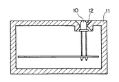
このようなガス漏れ警報器の一例として、図11に示すように、筐体としてのケース11の正面に開口部12設け、LED10を直接露出するタイプのものが知られている。ところで、台所は人や物の動きが頻繁に発生であり、衝突によるLED10の破損を防止する必要がある。このため、LED10は一般に、ガス漏れ警報器のケース11から引っ込んだ位置に配置し、LED10がケース11から突出しないようになっている。
【0004】
【発明が解決しようとする課題】
上述したようにガス漏れ警報器は、LPガスの場合は足下付近に、都市ガスの場合は天井側に配置されることが多い。また、部屋の隅にある壁に取付けて配置されることもある。
【0005】
このため、ガス漏れ警報器が足下に取付られている場合は、ユーザはガス漏れ警報器の上方からLED11を視認し、ガス漏れ警報器が天井側に取付られている場合は、ユーザはガス漏れ警報器の下方からLED11を視認する必要がある。また、ガス漏れ警報器が右隅にある壁や、左隅にある壁に取り付けられている場合は、ユーザはガス漏れ警報器の左右方向からLEDを確認する必要があり、正面からLED10を視認することができない。
【0006】
このため、ケース11から引っ込んだ位置に配置されているLED10の点灯、消灯或いは点滅を視認することができなくなる場合があるという問題があった。
【0007】
そこで、本発明は、上記のような問題点に着目し、正面以外の方向から発光素子の点灯状態を確実に見分けることができるガス漏れ警報器を提供することを課題とする。
【0008】
【課題を解決するための手段】
上記課題を解決するためになされた請求項1記載の発明は、ガス漏れを検出する検出手段と、該検出手段の検出結果を報知する発光素子と、前記検出手段及び前記発光素子を収容する筐体とを備えたガス漏れ警報器であって、前記発光素子は、前記筐体の一面に設けた開口部の背面側に配置され、前記開口部を覆い、かつ、前記発光素子からの光を散乱させる透光性の部材をさらに備えたことを特徴とするガス漏れ警報器に存する。
【0009】
請求項1記載の発明によれば、筐体の一面に設けた開口部の背面側に発光素子が配置される。この発光素子の正面側に、開口部を覆い、かつ、発光素子からの光を散乱させる透光性の部材が配置されている。従って、発光素子からの光を散乱することにより、開口部を覆う部材を面発光させることができる。
【0010】
請求項2記載の発明は、請求項1記載のガス漏れ警報器であって、前記部材全体が、前記発光素子の半値角内に入るように、前記部材の背面側に前記発光素子が配置されていることを特徴とするガス漏れ警報器に存する。
【0011】
請求項2記載の発明によれば、部材全体が、発光素子の半値角内に入るように、部材背面に発光素子が配置されている。このため、開口部を覆う部材全体を面発光させることができる。
【0012】
請求項3記載の発明は、請求項2記載のガス漏れ警報器であって、前記発光素子と前記部材との距離が最も短くなるように、前記部材の背面側に前記発光素子が配置されていることを特徴とするガス漏れ警報器に存する。
【0013】
請求項3記載の発明によれば、発光素子と部材との距離が最も短くなるように、部材の背面側に発光素子が配置されているため、部材を半値角内で最も明るく発光させることができる。
【0014】
請求項4記載の発明は、請求項1〜3何れか1項記載のガス漏れ警報器であって、前記発光素子の周囲に壁部が設けられていることを特徴とするガス漏れ警報器に存する。
【0015】
請求項4記載の発明によれば、発光素子の周囲に壁部が設けられている。従って、壁部での発光素子からの光の反射を利用して、部材−発光素子間の適切な距離を得ることができる。しかも、発光素子が2つ以上ある場合、互いの光が混ざらないようにすることができる。
【0016】
請求項5記載の発明は、請求項1〜4何れか1項記載のガス漏れ警報器であって、前記筐体は、箱型形状であり、前記筐体の一面と当該一面に対して直交する側面との間に、前記側面に近づくに従って、当該一面と対向する背面との距離が近づくテーパ面が設けられ、前記テーパ面に、前記開口部が設けられていることを特徴とするガス漏れ警報器に存する。
【0017】
請求項5記載の発明によれば、ガス漏れ警報器の筐体は、箱型形状である。この筐体の一面と、当該一面に対して直交する側面との間には、側面に近づくに従って、一面と対向する背面との距離が近づくテーパ面が設けられている。そして、このテーパ面に、開口部が設けられている。以上の構成によれば、筐体の背面を、ガス漏れ警報器を取り付けたい取付壁に向けて取り付ければ、一面側から視認できず、テーパ面が設けられる側面側から視認する必要があった場合に、開口部を覆う部材の視認性を向上することができる。
【0018】
従って、例えば、ガス漏れ警報器を部屋の足下付近にある側壁に取り付けたい場合は、テーパ面が設けられた側面を鉛直上向きに向け、背面を足下付近の側壁に向けて取り付ければ、上方から視認した場合に、開口部を覆う部材の視認性を向上することができる。また、ガス漏れ警報器を部屋の天井側にある側壁に取り付けたい場合は、テーパ面が設けられた側面を鉛直下向きに向け、背面を天井側の側壁に向けて取り付ければ、下方から視認した場合に、開口部を覆う部材の視認性を向上することができる。また、ガス漏れ警報器を部屋の隅にある側壁に取り付けたい場合は、テーパ面が設けられた側面を左右側に向け、背面を隅にある側壁に向けて取り付ければ、左右側から視認した場合に、開口部を覆う部材の視認性を向上することができる。さらに、ガス漏れ警報器を部屋の天井壁の側壁側に取り付けたい場合、テーパ面が設けられた側面を鉛直下向き、かつ、部屋の中心に向け、背面を天井壁に向けて取り付ければ、部屋の中心から天井を見上げて視認した場合に、開口部を覆う部材の視認性を向上することができる。
【0019】
請求項6記載の発明は、請求項5記載のガス漏れ警報器であって、前記発光素子は、通常発光素子と、該通常発光素子とは異なる発光色であり、かつ、ガス漏れが生じているとの前記検出結果が得られたときに点灯する警報発光素子とを有し、前記警報発光素子は、前記通常発光素子より前記側面側に設けられていることを特徴とするガス漏れ警報器に存する。
【0020】
請求項6記載の発明によれば、警報発光素子は、通常発光素子より側面側に設けられている。従って、警報発光素子及び通常発光素子が側面と平行な基板上に設けていた場合、警報発光素子−部材間の距離が、通常発光素子−部材間の距離よりも短くなるため、警報発光素子が発光したときの方が、通常発光素子が発光したときに比べて、部材を明るく発光させることができる。
【0021】
請求項7記載の発明は、請求項1〜4何れか1項記載のガス漏れ警報器であって、前記発光素子は、通常発光素子と、該通常発光素子とは異なる発光色であり、かつ、ガス漏れが生じているとの前記検出結果が得られたときに点灯する警報発光素子とを有し、前記通常発光素子及び前記警報発光素子の正面側には、単一の前記部材が配置されていることを特徴とするガス漏れ警報器に存する。
【0022】
請求項7記載の発明によれば、通常発光素子及び警報発光素子の正面側には、単一の部材が配置されている。従って、単一の部材を配置することにより、例えば、警報発光素子が発光していないとき、警報発光素子側の部材にも通常発光素子の光を導くことができるため、通常発光素子からの光により、部材が広範囲に面発光して見える。また、通常発光素子から遠ざかるに従って、部材の面発光輝度が小さくなる部分が生じ、グラデーションによる演出効果を得ることができる。
【0023】
請求項8記載の発明は、請求項7記載のガス漏れ警報器であって、前記通常発光素子と前記警報発光素子との間は遮光性の壁部によって仕切られており、前記通常発光素子又は前記警報発光素子からの光の、前記壁部の一方の側から他方の側への通過を許容する隙間又は、穴が前記壁部に設けられていることを特徴とするガス漏れ警報器に存する。
【0024】
請求項8記載の発明によれば、通常発光素子と警報発光素子との間は遮光性の壁部によって仕切られている。通常発光素子又は警報発光素子からの光の、壁部の一方の側から他方の側への通過を許容する隙間又は穴が壁部に設けられている。従って、壁部が設けられている場合であっても、隙間又は穴を設けることにより、通常発光素子又は警報発光素子からの光の、壁部の一方側から他方側へ通過が許容され、壁部の他方側にある部材にも入射される。このため、通常発光素子からの光により、部材がより広範囲に面発光して見える。また、警報発光素子からの光により、部材がより広範囲に面発光して見える。
【0025】
請求項9記載の発明は、請求項1〜4何れか1項記載のガス漏れ警報器であって、前記発光素子は、通常発光素子と、該通常発光素子とは異なる発光色であり、かつ、ガス漏れが生じているとの前記検出結果が得られたときに点灯する警報発光素子とを有し、前記通常発光素子及び前記警報発光素子の正面側には前記部材が配置されており、前記通常発光素子及び前記警報発光素子と前記部材との間に配設され、前記部材に対する前記通常発光素子からの光の入射領域が前記部材の前記警報発光素子側に拡大し、又は、前記部材に対する前記警報発光素子からの光の入射領域が前記部材の前記通常発光素子側に拡大するように、前記通常発光素子又は前記警報発光素子からの光を導光する導光部を設けたことを特徴とするガス漏れ警報器。
【0026】
請求項9記載の発明によれば、通常発光素子及び警報発光素子の正面側には部材が配置されている。通常発光素子及び警報発光素子と部材との間に配設され、部材に対する通常発光素子からの光の入射領域が部材の警報発光素子側に拡大し、又は、部材に対する警報発光素子からの光の入射領域が部材の通常発光素子側に拡大するように、通常発光素子又は警報発光素子からの光を導光する導光部を設けた。従って、導光部を設けることにより、通常発光素子からの光により、部材がより広範囲に面発光して見える。また、警報発光素子からの光により、部材がより広範囲に面発光して見える。
【0027】
請求項10記載の発明は、請求項1〜9何れか1項記載のガス漏れ警報器であって、前記部材の周縁には、前記背面側に突起する凸部が形成され、前記凸部の外側面が前記筐体外に露出されていることを特徴とするガス漏れ警報器に存する。
【0028】
請求項10記載の発明によれば、部材の周縁には、背面側に突起する凸部が形成され、この凸部の外側面が筐体外に露出されている。このため、凸部の外側面からも筐体外に向かって光が出射されるため、広範囲から発光素子の点灯状態を見分けることができる。
【0029】
請求項11記載の発明は、請求項10記載のガス漏れ警報器であって、前記部材と前記周縁に設けられた凸部とが成す内周角又は外周角には、曲率が付けられていることを特徴とするガス漏れ警報器に存する。
【0030】
請求項11記載の発明によれば、部材と周縁に設けられた凸部とが成す内周角又は外周角に曲率を付けることにより、発光素子からの光と曲率を付けた部分とが略直交し、内周角又は外周角での発光素子の反射を抑えて、より多くの光が部材を透過することができる。
【0031】
請求項12記載の発明は、ガス漏れを検出する検出手段と、該検出手段の検出結果を報知する発光素子と、前記検出手段及び前記発光素子を収容する筐体とを備えたガス漏れ警報器であって、前記筐体には開口部が設けられ、前記開口部を覆い、かつ、前記発光素子からの光を、当該発光素子の出射面積より大きい前記開口部を覆っている面全体に導光させる導光板をさらに備えることを特徴とするガス漏れ警報器に存する。
【0032】
請求項12記載の発明によれば、筐体の一面に設けた開口部は、発光素子からの光を、その発光素子の出射面積より大きい面全体に導光させる導光板によって覆われている。従って、発光素子からの光を、導光板において、面全体に導光させ、開口部を覆う面全体を発光させることができる。また、基板に搭載される発光素子の設置位置の都合により、発光素子が開口部の背面側に配置できないことがあっても、導光板を用いることにより、開口部を覆う面全体を発光させることができる。
【0033】
【発明の実施の形態】
第1実施形態
以下、この発明の第1実施形態を、図面を参照して説明する。
図1は、本発明のガス漏れ警報器の第1実施形態を示す部分断面図である。同図に示すように、ガス漏れ警報器の筐体としてのケース20には、ガス漏れを検出する検出手段としてのガスセンサ(図示せず)と、このガスセンサがガス漏れを検出したとき点灯する発光素子、警報発光素子としての赤色発光ダイオード(以下、赤色LED)21Rとが収容されている。この赤色LED21Rは、ケース20内部に設置された基板26に搭載されている。
【0034】
また、上記ケース20の正面には、開口部22が設けられ、この開口部22を覆うように乳白色の半透明性ポリカーボネート板23(以下、PC板23)が配置されている。このPC板23は、請求項中の部材に相当し、内部に分散された結晶によって光が散乱するものである。また、このPC板23の周縁には、背面に向かって突起する凸部23aが設けられ、凸部23aの外側面23a−1がケース20外に露出されている。さらに、このPC板23と、周縁に設けられた凸部23aとがなす内周角R1及び外周角R2には曲率がつけられている。
【0035】
そして、このPC板23の背面側に赤色LED21Rが配置されている。さらに、この赤色LED21Rの周囲には、白色の壁部24が設けられている。また、上記赤色LED21R及びPC板23は、PC板23全体が赤色LED21Rの半値角θ1/2内に入り、かつ、両者の距離が最も短くなるような位置に配置されている。
【0036】
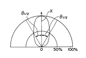
ここで半値角θ1/2について、図2を参照して説明する。図2は、赤色LED21Rの指向特性を示す図であり、赤色LED21Rの軸X上の光度を100%としたときに、赤色LED21Rに対して任意角度傾いた方向から見える光度の割合を示したものである。そして半値角とは、赤色LED21Rの軸X上の光度を100%としたとき、ちょうど50%の光度となる角度θ1/2をいう。
【0037】
以上の構成のガス漏れ警報器によれば、光を散乱する乳白色のPC板23によって、ケース20の一面に設けた開口部22を覆い、その開口部22の背面側に赤色LED21Rを配置している。これにより、赤色LED21Rが発光すると、赤色LED21RからPC板23に直接入射される光L1や、壁部24で反射された後に入射される光L2が、PC板23内部で散乱し、PC板23自体が発光して見える。つまり、開口部22を覆う面が発光して見え、赤色LED21Rがケース20から引っ込んでいたとしても、正面以外の方向から赤色LED21Rの点灯状態を確実に見分けることができる。
【0038】
また、上述したようにガス漏れ警報器は、PC板23全体が赤色LED21Rの半値角θ1/2内に入るように、赤色LED21R及びPC板23が配置されている。このため、PC板23の端の方まで発光して、開口部22を覆う面全体が発光して見え、正面以外の方向から赤色LED21Rの点灯状態をより一層確実に見分けることができる。
【0039】
また、上述したガス漏れ警報器によれば、半値角θ1/2内において、赤色LED21R−PC板23間の距離が最も短くなるように、赤色LED21R及びPC23が配置されている。このため、PC板23を半値角θ1/2内で最も明るく発光させることができる。
【0040】
また、上述したガス漏れ警報器は、赤色LED21Rの周囲に壁部24を設けている。このため、壁部24での赤色LED21Rからの光L2の反射を利用して、PC板23−赤色LED21R間の適切な位置を得ることができる。しかも、赤色LED21Rの他に、例えばガス漏れ警報器作動時に常時点灯する青色発光ダイオード(青色LED)が近くに配置されている場合、互いの光が混ざらないようにすることができる。また、この壁部24には、白色塗料が塗布されている。これにより、この壁部24での赤色LED21Rからの光の反射率を高め、より多くの光がPC板23に入射される。
【0041】
また、凸部23aの外側面23a−1をケース20外に露出させることにより、凸部23aの外側面からも光が出射されるため、より広範囲において、赤色LED21Rの点灯状態を見分けることができる。さらに、内周角R1及び外周角R2に曲率を付けることにより、LED21Rからの光と曲率を付けた部分とが略直交し、内周角R1及び外周角R2での赤色LED21Rからの光の反射を抑えて、より多くの光がPC板23に入射される。
【0042】
また、開口部22をPC板23で覆うことにより、ケース22内部への埃の侵入を防ぎ、埃によって生じる静電気により内部回路が誤動作してしまうことも防止することができる。
【0043】
なお、上述した第1実施形態では、図1に示すように、PC板23全体が赤色LED21Rの半値角θ1/2内に入るようにPC板23と赤色LED21Rとを配置していた。しかしながら、例えば、図3に示すように、PC板23全体が半値角θ1/2内とならないようにして、一点集中型のスポットライトタイプとしても使用することも考えられる。
【0044】
また、上述した第1実施形態では、半値角θ1/2内において、赤色LED21R−PC板23間の距離が最も短くなるように、赤色LED21R及びPC23が配置されている。しかしながら、赤色LED21Rの輝度が十分明るければ、赤色21R−PC板23間の距離を離すことも考えられる。
【0045】
また、上述した第1実施形態としては、赤色LED21Rの正面にある開口部22を乳白色のPC板23によって覆っていた。このPC板23は、内部の分散された結晶によって光を散乱するものであった。しかしながら、例えば、光透過板の表面に凹凸を付けるなどの表面加工を施すことにより、光が表面部分で散乱するようなものによって、開口部22を覆うようにすることも考えられる。
【0046】
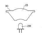
また、上述したPC板23の形状を、図4に示すように、正面側の表面を凸レンズ形状にして、赤色LED21Rの光を拡大したり、背面側の表面に曲率を付けて、より多くの赤色LED21Rからの光をPC板23内部に入射することも考えられる。また、凸レンズ形状以外の部分に光を散乱させる表面加工30を施すことも考えられる。
【0047】
第2実施形態
次に、この発明の第2実施の形態について説明する。
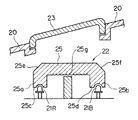
図5(a)及び(b)は、本発明のガス漏れ警報器の第2実施形態を示す正面図及び側面図である。図6は、図5(a)に示すガス漏れ警報器のA−A線部分断面図である。第2実施形態のガス漏れ警報器のケース20には、第1実施形態と同様に、ガス漏れを検出する図示しないガスセンサ(=検出手段)と、このガスセンサがガス漏れを検出したとき点灯する赤色LED21R(図6)と、作動時に常時点灯する青色LED21B(図6)が収容されている。この赤色LED21R及び青色LED21Bは、ケース20内部に設置された基板26に搭載されている。
【0048】
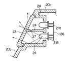
また、ガス漏れ警報器は、図5に示すように、ケース20の一面である正面20bとこの正面20bに対して直交する側面20cとの間に、側面20cに近づくに従って、正面20bと対向する背面20aとの距離が近づくテーパ面20dが設けられている。
【0049】
そして、このテーパ面20dには、図6に示すように、開口部22が設けられ、この開口部22を覆うように上述した第1実施形態と同様のPC板23が配置されている。そして、このPC板23の背面側に上記赤色LED21R及び青色LED21Bが配置されている。さらに、赤色LED21R及び発光素子、通常発光素子としての青色LED21Bの周囲にはそれぞれ壁部24が設けられている。
【0050】
以上のように、テーパ面20dに開口部22を設けることにより、ガス漏れ警報器を正面20b側から視認できず、側面20c側から視認する必要があった場合でも、開口部22を覆うPC板23の面発光が視認し易くなり、赤色LED21Rや青色LED21Bの点灯状態を確実に見分けることができる。
【0051】
従って、例えば、ガス漏れ警報器を部屋の足下付近にある側壁に取り付けたい場合は、テーパ面20dが設けられた側面20cを鉛直上向きに向け、背面20aを足下付近の側壁に向けて取り付ければ、上方から視認した場合に、開口部22を覆うPC板23の視認性を向上することができる。また、ガス漏れ警報器を部屋の天井側にある側壁に取り付けたい場合は、テーパ面20dが設けられた側面20cを鉛直下向きに向け、背面20aを天井側の側壁に向けて取り付ければ、下方から視認した場合に、開口部22を覆うPC板23の視認性を向上することができる。
【0052】
また、ガス漏れ警報器を部屋の隅にある側壁に取り付けたい場合は、テーパ面20dが設けられた側面20cを左右側に向け、背面20aを隅にある側壁に向けて取り付ければ、左右側から視認した場合に、開口部22を覆うPC板23の視認性を向上することができる。ガス漏れ警報器を部屋の天井壁の側壁側に取り付けたい場合、テーパ面20dが設けられた側面20cを鉛直下向き、かつ、部屋の中心に向け、背面20aを天井壁に向けて取り付ければ、部屋の中心から天井を見上げて視認した場合に、開口部22を覆うPC板23の視認性を向上することができる。
【0053】
また、図6に示すように、赤色LED21Rは、青色LED21Bより鉛直上向き方向にある側面20c側に設けられている。これは、赤色及び青色LED21R、21Bが側面20bと平行な基板26上に設けていた場合、赤色LED21R−PC板23間の距離が、青色LED21R−PC板23間の距離よりも短くなるため、赤色LED21Rが発光したときの方が、青色LED21Bが発光したときに比べて、PC板23を明るく発光させることができる。
【0054】
また、以上のガス漏れ警報器によれば、単一のPC板23の背面に赤色LED21R及び青色21Bが配置されている。従って、赤色LED21Rが発光していないときは、赤色LED21R側のPC板23にも青色21Bの光を積極的に導くことができ、赤色LED21R側のPC板23が青っぽく視認される。このため青色LED21Bからの光によって、PC板23を広範囲に発光させることができるため、青色LED21B−PC板23の距離が赤色21R−PC23間の距離より長いからといって、青色LED21Bの点灯状態が見分けにくいということがない。
【0055】
また、単一のPC板23を配置して、PC板23を大きくすることにより、青色LED21Bから遠ざかるに従って、PC板23の面発光輝度が小さくなる部が生じ、グラデーションによる演出効果を得ることができる。
【0056】
また、単一のPC板23を配置することにより、警報時には、青色LED21Bが消灯し、赤色LED21Rのみが発光するような場合は、青色LED21B側のPC板23にも赤色LED21Rの光を積極的に導くことができ、青色LED21B側のPC板23が赤っぽく視認される。このため赤色LED21Rからの光によって、PC板23を広範囲に発光させることができるため、赤色LED21R、青色LED21Bの点灯状態が見分け易くなる。また、同様にグラデーションによる演出効果も得ることができる。
【0057】
なお、上述した第2実施形態によれば、PC板23には、図6に示すように、赤色LED21Rと青色LED21Bとの境界に凹部を形成していた。しかしながら、例えば、図7に示すように、凹部を形成せず、フラットに形成すれば、より一層青色LED21Bや、赤色LED21Rからの光によって、PC板23が広範囲に発光する。
【0058】
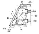
また、図7に示すように、赤色LED21Rと青色LED21Bとの間に設けられた壁部24を低くして、PC板23と壁24との間に隙間27を設けると、その隙間27によって、青色LED21Bからの光の、壁部24より赤色LED21R側への通過が許容される。このため、青色LED21Bからの光が壁部24より赤色LED32R側のPC板23にも入射される。一方、隙間27によって、赤色LED21Bからの光の、壁部24より青色LED21R側への通過が許容され、赤色LED21Rからの光が壁部24より青色LED32B側のPC板23にも入射される。このため、赤色LED21Rのみ、又は、青色LED21Bのみを発光したとき、その光によって、PC板23が広範囲に面発光するようになる。
【0059】
また、隙間27を設けなくても、例えば、赤色LED21Rと青色LED21Bとの間に設けられた壁部24のどこかに、穴を開けることによっても、青色LED21B又は赤色LED21Rからの光によって、PC板23をより広範囲に発光するようにできる。
【0060】
さらに、図8に示すように、PC板23の赤色LED21R及び青色LED21B側と突出させて、青色LED21Bからの光を、赤色LED21R側のPC板23に向かって屈折させる屈折面28aが形成されたプリズム28を設けることも考えられる。
【0061】
この屈折面28aにより、青色LED21Bからの光の、PC板23に対する入射領域が、PC板23の赤色LED21R側まで拡大するように、青色LED21Bからの光を導光することができる。従って、青色LED21Bのみを発光したとき、その光によって、PC板23が広範囲に面発光するようになる。なお、図8では、赤色LED21Rと青色LED21Bとの間に設けられた壁部24を図7に比べて、さらに低くして、隙間27を大きくすることによっても、赤色LED21Rのみ、又は、青色LED21Bのみを発光したとき、その光によって、PC板23が広範囲に発光するようになっている。
【0062】
また、図8に示す場合、プリズム28に設けた屈折面28aは、青色LED21Bからの光を、赤色LED21R側のPC板23に向かって屈折させるように設けていたが、逆に、赤色LED21Rからの光を、青色LED21B側のPC板23に向かって屈折させるように設けてもよい。
【0063】
また、図8では、PC板23の一部を突出させて、屈折面28aが形成されたプリズム28を設けていた。つまり、PC板23とプリズム28aとは同一の部材で一体に形成されている。しかしながら、プリズム28aまでも光を散乱させるPC板23と同一部材で形成すると、折角、青色LED21Bからの光を、赤色LED21R側のPC板23に向かって屈折させる屈折面28aを設けても、屈折面28aで屈折した光の一部は散乱されて赤色LED21R側のPC板23に導かれない。同様に、赤色LED21Rからの光を、青色LED21B側のPC板23に向かって屈折させる屈折面28aを設けても、屈折面28aで屈折した光の一部は散乱されて青色LED21B側のPC板に導かれない。
【0064】
そこで、プリズム28部分については、透明部材により形成することも考えられる。このようにすれば、プリズム28部分で散乱が起こらず、屈折面28aで屈折された光のほとんどが赤色LED21R側又は青色LED21B側のPC板23に導かれるようになる。従って、赤色LED21Rのみ、又は、青色LED21Bのみを発光したとき、その光によって、PC板23が広範囲に発光するようになる。
【0065】
この透明部材から形成されたプリズム28は、例えば、二色形成により、PC板23と一体に形成することや、PC板23と別々に形成して、組立の時に接着させることも考えられる。
【0066】
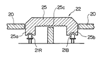
さらに、図9に示すように、PC板23と赤色LED21R及び青色LED21Bとの間に、導光板25を配置することも考えられる。この導光板25の正面側の面は、赤色LED21R及び青色LED21Bの出射面積より大きい。そして、この導光板25には、背面側に向かって突起する集光部25a及び25bが形成されている。この集光部25a及び25bには、それぞれ略半球形状の穴が設けられた集光面25c及び25dが設けられ、この集光面25c及び25dに設けられた略半球形状の穴に赤色LED21R、青色LED21Bの一部がそれぞれ挿入されている。
【0067】
さらに、導光板25には、集光部25aを導光した赤色LED21Rからの光を青色LED21B側に反射する反射面25eと、集光部25bを導光した青色LED21Bからの光を赤色LED21R側に反射する反射面25fと、背面側に形成した反射面25gとが設けられる。
【0068】
以上のような構成によれば、青色LED21Bからの光は、集光面25dから集光部25bに入射され、反射面25fに向かって集光部25bを導光する。そして、反射面25fに到達した光は、反射面25fで赤色LED21R側の導光板25に向かう。そして、その後、反射面25gで反射されたりして、導光板25全体に導かれ、導光板25全体が発光する。このため、導光板25により、青色LED21Bからの光の、PC板23に対する入射領域が赤色LED21側まで拡大するように、青色LED21bからの光を導光することができる。従って、青色LED21Bのみを発光したとき、その光によって、PC板23が広範囲に面発光するようになる。
【0069】
また、赤色LED21Rからの光は、集光面25cから集光部25aに入射され、反射面25eに向かって集光部25aを導光する。そして、反射面25eに到達した光は、反射面25eで青色LED21B側の導光板25に向かう。そして、その後、反射面25gで反射されたりして、導光板25全体に導かれ、導光板25全体が発光する。このため、導光板25により、赤色LED21Rからの光の、PC板23に対する入射領域が青色LED21B側まで拡大するように、赤色LED21Rからの光を導光することができる。従って、赤色LED21Rのみを発光したとき、その光によって、PC板23が広範囲に面発光するようになる。
【0070】
以上のことから明らかなように、プリズム28に設けた屈折面28a又は導光板25が、請求項中の導光部に相当する。
【0071】
また、上述した第2実施形態によれば、赤色LED21R及び青色LED23Bの正面側には単一のPC板23を設けていた。しかしながら、例えば、赤色LED21Rの正面側と、青色LED23Bの正面側とに、それぞれ別体のPC板23を配置することも考えられる。この場合も、屈折面28aを設けたり、導光板25を設けたりすれば、同様に、青色LED21Bからの光が赤色LED21R側のPC板23に導かれたり、赤色LED21Rからの光が赤色LED21R側のPC板23に導かれたりして、広範囲に発光する。
【0072】
また、第2実施形態においては、PC板23における光の散乱度合については、何も述べなかったが、例えば、均一の散乱度合にすることが考えられる。また、PC板23の赤色LED21R側の散乱度合を、PC板23の青色LED21B側の散乱度合より大きくすることが考えられる。これは、赤色LED21Rの方がPC板23との距離が短く、赤色LED21Rからの光の拡散が小さく、面発光面積が小さくなる恐れがあるからである。
【0073】
また、上述した第1及び第2実施形態によれば、光を散乱する材質であるPC板23によって開口部22を覆っていた。しかしながら、例えば、開口部を覆う部材の赤色又は青色LED21R、21B側の面や、赤色又は青色LED21R、21Bとは反対側の面に、光を散乱させる凹凸面を施すことによっても、光を散乱させることができる。
【0074】
第3実施形態
次に、本発明の第3実施形態について、以下説明する。
図10は、本発明のガス漏れ警報器の第3実施の形態を示す部分断面図である。同図に示すように、第3実施形態のガス漏れ警報器のケース20には、ガス漏れを検出する図示しないガスセンサ(=検出手段)と、このガスセンサがガス漏れを検出したとき点灯する赤色LED21Rと、ガスセンサがガス漏れを検出していないとき点灯する青色LED21Bが収容されている。
【0075】
また、上記ケース20の一面には、開口部22が設けられ、この開口部22を覆うように導光板25が配置されている。導光板25は、図10で説明した導光板と同様の構成である。
【0076】
以上の構成によれば、ガス漏れが生じていないとの検出結果が得られ、青色LED21Bが発光すると、青色LED21Bからの光が導光板25に導光し、青色で導光板25の正面側の面全体が発光する。これに対して、ガス漏れが生じているとの検出結果が得られ、赤色LED21Rが発光すると、赤色LED21Rからの光が導光板25に導光し、赤色で導光板25の正面側の面全体が発光するため、視認性向上を図ることができる。
【0077】
また、基板に搭載される赤色LED21R及び青色LED21Bの設置位置の都合により、赤色LED21R及び青色LED21Bが開口部22の背面側に配置できないことがあっても、導光板25を用いることにより、開口部22を覆う面全体を発光させることができる。
【0078】
【発明の効果】
以上説明したように、請求項1記載の発明によれば、発光素子からの光を散乱することにより、開口部を覆う部材を面発光させることができるので、正面以外の方向から発光素子の点灯状態を確実に見分けることができるガス漏れ警報器を得ることができる。
【0079】
請求項2記載の発明によれば、開口部を覆う部材全体を面発光させることができるので、正面以外の方向から発光素子の点灯状態をより確実に見分けることができるガス漏れ警報器を得ることができる。
【0080】
請求項3記載の発明によれば、部材を半値角内で最も明るく発光させることができるので、正面以外の方向から発光素子の点灯状態をより確実に見分けることができるガス漏れ警報器を得ることができる。
【0081】
請求項4記載の発明によれば、発光素子の周囲に壁部が設けられている。従って、壁部での発光素子からの光の反射を利用して、部材−発光素子間の適切な距離を得ることができる。しかも、発光素子が2つ以上ある場合、互いの光が混ざらないようにすることができるガス漏れ警報器を得ることができる。
【0082】
請求項5記載の発明によれば、例えば、ガス漏れ警報器を部屋の足下付近にある側壁に取り付けたい場合は、テーパ面が設けられた側面を鉛直上向きに向け、背面を足下付近の側壁に向けて取り付ければ、上方から視認した場合に、開口部を覆う部材の視認性を向上することができる。また、ガス漏れ警報器を部屋の天井側にある側壁に取り付けたい場合は、テーパ面が設けられた側面を鉛直下向きに向け、背面を天井側の側壁に向けて取り付ければ、下方から視認した場合に、開口部を覆う部材の視認性を向上することができる。また、ガス漏れ警報器を部屋の隅にある側壁に取り付けたい場合は、テーパ面が設けられた側面を左右側に向け、背面を隅にある側壁に向けて取り付ければ、左右側から視認した場合に、開口部を覆う部材の視認性を向上することができる。さらに、ガス漏れ警報器を部屋の天井壁の側壁側に取り付けたい場合、テーパ面が設けられた側面を鉛直下向き、かつ、部屋の中心に向け、背面を天井壁に向けて取り付ければ、部屋の中心から天井を見上げて視認した場合に、開口部を覆う部材の視認性を向上することができるので、発光素子の点灯状態をより確実に見分けることができるガス漏れ警報器を得ることができる。
【0083】
請求項6記載の発明によれば、警報発光素子及び通常発光素子が側面と平行な基板上に設けていた場合、警報発光素子−部材間の距離が、通常発光素子−部材間の距離よりも短くなるため、警報発光素子が発光したときの方が、通常発光素子が発光したときに比べて、部材を明るく発光させることができるので、警報発光素子の点灯状態をより確実に見分けることができるガス漏れ警報器を得ることができる。
【0084】
請求項7記載の発明によれば、単一の部材を配置することにより、例えば、警報発光素子が発光していないとき、警報発光素子側の部材にも通常発光素子の光を積極的に導くことができるため、通常発光素子からの光により、部材が広範囲に面発光して見えるので、正面以外の方向から通常発光素子の点灯状態をより確実に見分けることができる。また、通常発光素子から遠ざかるに従って、部材の面発光輝度が小さくなる部分が生じ、グラデーションによる演出効果を得ることができるガス漏れ警報器を得ることができる。
【0085】
請求項8記載の発明によれば、壁部が設けられている場合であっても、隙間又は穴を設けることにより、通常発光素子又は警報発光素子からの光の、壁部の一方側から他方側へ通過が許容され、壁部の他方側にある部材にも入射される。このため、通常発光素子からの光により、部材がより広範囲に面発光して見える。また、警報発光素子からの光により、部材がより広範囲に面発光して見えるので、正面以外の方向から通常発光素子の点灯状態をより確実に見分けることができるガス漏れ警報器を得ることができる。
【0086】
請求項9記載の発明によれば、導光部を設けることにより、通常発光素子からの光により、部材がより広範囲に面発光して見える。また、警報発光素子からの光により、部材がより広範囲に面発光して見えるので、正面以外の方向から通常発光素子の点灯状態をより確実に見分けることができるガス漏れ警報器を得ることができる。
【0087】
請求項10記載の発明によれば、凸部の外側面からも筐体外に向かって光が出射されるため、広範囲から発光素子の点灯状態を見分けることができるガス漏れ警報器を得ることができる。
【0088】
請求項11記載の発明によれば、発光素子からの光と曲率を付けた部分とが略直交し、部材での発光素子の反射を抑えて、より多くの光が部材を透過することができるので、正面以外の方向から発光素子の点灯状態をより確実に見分けることができるガス漏れ警報器を得ることができる。
【0089】
請求項12記載の発明によれば、発光素子からの光を、導光板において、面全体に導光させ、開口部を覆う面全体を光輝させることができるので、正面以外の方向から発光素子の点灯状態を確実に見分けることができる。しかも、基板に搭載される発光素子の設置位置の都合により、発光素子が開口部の背面側に配置できないことがあっても、導光板を用いることにより、開口部を覆う面全体を発光させることができるガス漏れ警報器を得ることができる。
【図面の簡単な説明】
【図1】本発明のガス漏れ警報器の第1実施形態を示す部分断面図である。
【図2】半値角を説明するための指向特性図である。
【図3】本発明のガス漏れ警報器の他の実施形態を示す部分断面図である。
【図4】本発明のガス漏れ警報器の他の実施形態を示す部分断面図である。
【図5】(a)及び(b)は、本発明のガス漏れ警報器の第2実施形態を示す正面図及び側面図である。
【図6】図5(a)に示すガス漏れ警報器のA−A線部分断面図である。
【図7】図5(a)に示すガス漏れ警報器の他の実施形態におけるA−A線部分断面図である。
【図8】図5(a)に示すガス漏れ警報器の他の実施形態におけるA−A線部分断面図である。
【図9】図5(a)に示すガス漏れ警報器の他の実施形態におけるA−A線部分断面図である。
【図10】第3実施形態におけるガス漏れ警報器の部分断面図である。
【図11】従来のガス漏れ警報器の一例を示す断面図である。
【符号の説明】
20d テーパ面
21R 赤色LED(発光素子、警報発光素子)
21B 青色LED(発光素子、通常発光素子)
22 開口部
23 PC板(部材)
28a 屈折面(導光部)
24 壁部
25 導光板(導光部)
27 隙間
R1 内周角
R2 外周角
θ1/2 半値角[0001]
BACKGROUND OF THE INVENTION
The present invention relates to a gas leak alarm, and more particularly, to a gas leak alarm provided with a light emitting element.
[0002]
[Prior art]
A gas leak alarm used to detect city gas and LP gas leaks is used for wall surfaces of kitchens that use gas (in the case of city gas that is lighter than air, near the ceiling, and LP gas that is heavier than air) In the case near the feet). And, it can be configured to recognize the gas leakage alarm device power-on (normal operation) state and gas leakage detection state by observing the lighting state of the LED provided in the gas leakage alarm device, such as lighting, extinguishing or blinking. Has been.
[0003]
As an example of such a gas leak alarm device, as shown in FIG. 11, a type in which an
[0004]
[Problems to be solved by the invention]
As described above, the gas leak alarm is often arranged near the feet in the case of LP gas and on the ceiling side in the case of city gas. It may also be placed on a wall in the corner of the room.
[0005]
For this reason, when the gas leak alarm is attached to the foot, the user visually recognizes the
[0006]
For this reason, there existed a problem that it became impossible to visually recognize lighting, extinction, or blinking of LED10 arrange | positioned in the position retracted from the
[0007]
Therefore, the present invention focuses on the above-described problems, and an object of the present invention is to provide a gas leak alarm device that can reliably distinguish the lighting state of the light emitting element from directions other than the front.
[0008]
[Means for Solving the Problems]
In order to solve the above-mentioned problems, the invention according to
[0009]
According to the first aspect of the present invention, the light emitting element is disposed on the back side of the opening provided on one surface of the housing. A translucent member that covers the opening and scatters light from the light emitting element is disposed on the front side of the light emitting element. Therefore, by scattering light from the light emitting element, the member covering the opening can be surface-emitted.
[0010]
The invention according to claim 2 is the gas leak alarm according to
[0011]
According to invention of Claim 2, the light emitting element is arrange | positioned on the member back surface so that the whole member may enter in the half value angle of a light emitting element. For this reason, the whole member which covers an opening can be surface-emitted.
[0012]
A third aspect of the present invention is the gas leak alarm according to the second aspect, wherein the light emitting element is arranged on the back side of the member so that the distance between the light emitting element and the member is the shortest. It exists in the gas leak alarm characterized by being.
[0013]
According to the third aspect of the present invention, since the light emitting element is arranged on the back side of the member so that the distance between the light emitting element and the member is the shortest, the member can be caused to emit the brightest light within the half-value angle. it can.
[0014]
The invention according to claim 4 is the gas leak alarm device according to any one of
[0015]
According to the invention of claim 4, the wall portion is provided around the light emitting element. Therefore, an appropriate distance between the member and the light emitting element can be obtained by utilizing reflection of light from the light emitting element at the wall portion. In addition, when there are two or more light emitting elements, it is possible to prevent light from mixing with each other.
[0016]
A fifth aspect of the present invention is the gas leak alarm according to any one of the first to fourth aspects, wherein the casing has a box shape and is orthogonal to the one surface of the casing and the one surface. The gas leakage is characterized in that a taper surface is provided between the side surface and the side surface to be closer to the back surface facing the one surface, and the opening is provided in the taper surface. It exists in the alarm device.
[0017]
According to the invention described in claim 5, the casing of the gas leak alarm has a box shape. A tapered surface is provided between the one surface of the housing and the side surface orthogonal to the one surface so that the distance between the one surface and the back surface facing the one surface approaches the side surface. An opening is provided in the tapered surface. According to the above configuration, if the rear surface of the housing is attached to the mounting wall to which the gas leak alarm is to be attached, it is not possible to see from one side, and it is necessary to see from the side where the tapered surface is provided Furthermore, the visibility of the member covering the opening can be improved.
[0018]
Therefore, for example, if you want to install the gas leak alarm on the side wall near the foot of the room, you can see it from above if you attach the side with the taper surface vertically upward and the back to the side wall near the foot. When it does, the visibility of the member which covers an opening part can be improved. Also, if you want to install the gas leak alarm on the side wall on the ceiling side of the room, if the side with the tapered surface is directed vertically downward and the rear side is mounted on the side wall on the ceiling side, it will be viewed from below Furthermore, the visibility of the member covering the opening can be improved. Also, if you want to attach the gas leak alarm to the side wall at the corner of the room, the side with the tapered surface is directed to the left and right, and the back is directed to the side wall at the corner, and viewed from the left and right sides Furthermore, the visibility of the member covering the opening can be improved. In addition, if you want to install the gas leak alarm on the side wall of the ceiling wall of the room, attach the side with the taper surface vertically downward, toward the center of the room, and the back toward the ceiling wall. When the ceiling is viewed from the center and viewed, the visibility of the member covering the opening can be improved.
[0019]
The invention according to claim 6 is the gas leak alarm device according to claim 5, wherein the light emitting element is a normal light emitting element and a light emission color different from that of the normal light emitting element, and gas leakage occurs. And a warning light emitting element that is turned on when the detection result is obtained, wherein the warning light emitting element is provided on the side surface side from the normal light emitting element. Exist.
[0020]
According to the sixth aspect of the present invention, the alarm light emitting element is provided on the side surface side of the normal light emitting element. Therefore, when the alarm light emitting element and the normal light emitting element are provided on the substrate parallel to the side surface, the distance between the alarm light emitting element and the member is shorter than the distance between the normal light emitting element and the member. When the light is emitted, the member can emit light brighter than when the normal light emitting element emits light.
[0021]
Invention of Claim 7 is a gas leak alarm device of any one of Claims 1-4, Comprising: The said light emitting element is a luminescent color different from a normal light emitting element, and this normal light emitting element, and A warning light emitting element that is turned on when the detection result that gas leakage has occurred is obtained, and a single member is disposed on the front side of the normal light emitting element and the warning light emitting element. It exists in the gas leak alarm characterized by being made.
[0022]
According to the seventh aspect of the present invention, a single member is disposed on the front side of the normal light emitting element and the alarm light emitting element. Therefore, by arranging a single member, for example, when the alarm light emitting element is not emitting light, the light of the normal light emitting element can be guided to the member on the alarm light emitting element side. Thus, the member appears to emit light in a wide range. Further, as the distance from the normal light emitting element is increased, a portion where the surface emission luminance of the member decreases is generated, and an effect of gradation can be obtained.
[0023]
Invention of Claim 8 is a gas leak alarm device of Claim 7, Comprising: Between the said normal light emitting element and the said alarm light emitting element is divided by the light-shielding wall part, The said normal light emitting element or The gas leakage alarm device is characterized in that a gap or a hole allowing passage of light from the warning light emitting element from one side of the wall portion to the other side is provided in the wall portion. .
[0024]
According to the eighth aspect of the invention, the normal light emitting element and the alarm light emitting element are partitioned by the light shielding wall. A gap or a hole that allows passage of light from the normal light emitting element or the warning light emitting element from one side of the wall portion to the other side is provided in the wall portion. Therefore, even when a wall portion is provided, by providing a gap or a hole, light from a normal light emitting element or an alarm light emitting element is allowed to pass from one side of the wall portion to the other side, and the wall It is also incident on the member on the other side of the part. For this reason, the member appears to emit light in a wider range by the light from the normal light emitting element. Further, the member appears to emit light in a wider range by the light from the alarm light emitting element.
[0025]
Invention of Claim 9 is a gas leak alarm device of any one of Claims 1-4, Comprising: The said light emitting element is a luminescent color different from a normal light emitting element, and this normal light emitting element, and An alarm light emitting element that is turned on when the detection result that gas leakage has occurred is obtained, and the member is arranged on the front side of the normal light emitting element and the alarm light emitting element, The normal light emitting element and the alarm light emitting element are disposed between the member and an incident area of light from the normal light emitting element to the member is expanded toward the alarm light emitting element side of the member, or the member A light guide portion for guiding light from the normal light emitting element or the alarm light emitting element is provided so that an incident area of light from the alarm light emitting element is expanded toward the normal light emitting element side of the member. Characteristic gas leak alarm.
[0026]
According to invention of Claim 9, the member is arrange | positioned at the front side of the normal light emitting element and the warning light emitting element. It is arranged between the normal light emitting element and the alarm light emitting element and the member, and the incident area of the light from the normal light emitting element to the member is expanded to the alarm light emitting element side of the member, or the light from the alarm light emitting element to the member A light guide unit that guides light from the normal light emitting element or the alarm light emitting element is provided so that the incident region expands to the normal light emitting element side of the member. Therefore, by providing the light guide unit, the member appears to emit light in a wider range by the light from the normal light emitting element. Further, the member appears to emit light in a wider range by the light from the alarm light emitting element.
[0027]
Invention of
[0028]
According to the tenth aspect of the present invention, a convex portion that protrudes toward the back side is formed on the periphery of the member, and the outer surface of the convex portion is exposed outside the casing. For this reason, since light is emitted toward the outside of the housing also from the outer surface of the convex portion, the lighting state of the light emitting element can be distinguished from a wide range.
[0029]
The invention according to
[0030]
According to the eleventh aspect of the invention, the curvature of the inner peripheral angle or the outer peripheral angle formed by the member and the convex portion provided at the peripheral edge allows the light from the light emitting element to be substantially orthogonal to the curved portion. And reflection of the light emitting element in an inner peripheral angle or an outer peripheral angle can be suppressed, and more light can permeate | transmit a member.
[0031]
According to a twelfth aspect of the present invention, there is provided a gas leak alarm device comprising: detection means for detecting a gas leak; a light emitting element for notifying a detection result of the detection means; and a housing for housing the detection means and the light emitting element. The housing is provided with an opening, covers the opening, and guides light from the light emitting element to the entire surface covering the opening larger than the emission area of the light emitting element. The gas leak alarm device further includes a light guide plate that emits light.
[0032]
According to the twelfth aspect of the present invention, the opening provided on one surface of the housing is covered with the light guide plate that guides light from the light emitting element to the entire surface larger than the emission area of the light emitting element. Therefore, the light from the light emitting element can be guided to the entire surface of the light guide plate, and the entire surface covering the opening can be caused to emit light. Moreover, even if the light emitting element cannot be arranged on the back side of the opening due to the installation position of the light emitting element mounted on the substrate, the entire surface covering the opening can be made to emit light by using the light guide plate. Can do.
[0033]
DETAILED DESCRIPTION OF THE INVENTION
First embodiment
Hereinafter, a first embodiment of the present invention will be described with reference to the drawings.
FIG. 1 is a partial cross-sectional view showing a first embodiment of a gas leak alarm according to the present invention. As shown in the figure, a
[0034]
An
[0035]
A red LED 21 </ b> R is disposed on the back side of the
[0036]
Where the half-value angle θ1/2Will be described with reference to FIG. FIG. 2 is a diagram showing the directivity characteristics of the
[0037]
According to the gas leak alarm having the above configuration, the milky
[0038]
In addition, as described above, the gas leakage alarm device has the half-value angle θ of the
[0039]
Further, according to the gas leak alarm described above, the half-value angle θ1/2Inside, the
[0040]
Moreover, the gas leak alarm mentioned above has provided the
[0041]
Further, by exposing the
[0042]
Further, by covering the
[0043]
In the first embodiment described above, as shown in FIG. 1, the
[0044]
In the first embodiment described above, the half-value angle θ1/2Inside, the
[0045]
Moreover, as 1st Embodiment mentioned above, the opening
[0046]
Further, as shown in FIG. 4, the shape of the
[0047]
Second embodiment
Next explained is the second embodiment of the invention.
5 (a) and 5 (b) are a front view and a side view showing a second embodiment of the gas leak alarm of the present invention. FIG. 6 is a partial cross-sectional view taken along line AA of the gas leak alarm shown in FIG. As in the first embodiment, the
[0048]
Further, as shown in FIG. 5, the gas leak alarm device faces the
[0049]
As shown in FIG. 6, the tapered
[0050]
As described above, by providing the
[0051]
Therefore, for example, when it is desired to attach the gas leak alarm to the side wall near the foot of the room, the
[0052]
If the gas leak alarm is to be attached to the side wall at the corner of the room, the
[0053]
Moreover, as shown in FIG. 6, the
[0054]
Moreover, according to the above gas leak alarm, red LED21R and blue 21B are arrange | positioned on the back surface of the
[0055]
Further, by arranging a
[0056]
Further, by arranging the
[0057]
Note that, according to the second embodiment described above, the
[0058]
Further, as shown in FIG. 7, when the
[0059]
Even if the
[0060]
Further, as shown in FIG. 8, a refracting surface 28a is formed so as to protrude from the
[0061]
By this refracting surface 28a, the light from the
[0062]
In the case shown in FIG. 8, the refracting surface 28a provided on the
[0063]
In FIG. 8, a part of the
[0064]
Therefore, the
[0065]
The
[0066]
Furthermore, as shown in FIG. 9, it is conceivable to arrange a
[0067]
Furthermore, the
[0068]
According to the above configuration, the light from the
[0069]
Further, the light from the
[0070]
As is clear from the above, the refracting surface 28a or the
[0071]
Moreover, according to 2nd Embodiment mentioned above, the
[0072]
In the second embodiment, nothing has been said about the degree of light scattering on the
[0073]
Further, according to the first and second embodiments described above, the
[0074]
Third embodiment
Next, a third embodiment of the present invention will be described below.
FIG. 10 is a partial sectional view showing a third embodiment of the gas leak alarm of the present invention. As shown in the figure, in the
[0075]
An
[0076]
According to the above configuration, a detection result that no gas leakage has occurred is obtained, and when the
[0077]
Even if the
[0078]
【The invention's effect】
As described above, according to the first aspect of the present invention, since the member covering the opening can be surface-emitted by scattering the light from the light emitting element, the light emitting element is turned on from a direction other than the front. It is possible to obtain a gas leak alarm that can reliably recognize the state.
[0079]
According to the second aspect of the present invention, since the entire member covering the opening can be surface-emitted, a gas leak alarm capable of more surely distinguishing the lighting state of the light emitting element from directions other than the front surface is obtained. Can do.
[0080]
According to the invention described in claim 3, since the member can emit light brightest within the half-value angle, it is possible to obtain a gas leak alarm that can more reliably distinguish the lighting state of the light emitting element from directions other than the front. Can do.
[0081]
According to the invention of claim 4, the wall portion is provided around the light emitting element. Therefore, an appropriate distance between the member and the light emitting element can be obtained by utilizing reflection of light from the light emitting element at the wall portion. In addition, when there are two or more light emitting elements, it is possible to obtain a gas leak alarm that can prevent mutual light from being mixed.
[0082]
According to the fifth aspect of the present invention, for example, when the gas leak alarm is to be attached to the side wall near the foot of the room, the side surface provided with the taper surface is directed vertically upward and the back surface is directed to the side wall near the foot. If it attaches toward, it can improve the visibility of the member which covers an opening, when visually recognizing from the upper part. Also, if you want to install the gas leak alarm on the side wall on the ceiling side of the room, if the side with the tapered surface is directed vertically downward and the rear side is mounted on the side wall on the ceiling side, it will be viewed from below Furthermore, the visibility of the member covering the opening can be improved. Also, if you want to attach the gas leak alarm to the side wall at the corner of the room, the side with the tapered surface is directed to the left and right, and the back is directed to the side wall at the corner, and viewed from the left and right sides Furthermore, the visibility of the member covering the opening can be improved. In addition, if you want to install the gas leak alarm on the side wall of the ceiling wall of the room, attach the side with the taper surface vertically downward, toward the center of the room, and the back toward the ceiling wall. Since the visibility of the member that covers the opening can be improved when the ceiling is viewed from the center, a gas leak alarm that can more reliably recognize the lighting state of the light emitting element can be obtained.
[0083]
According to the sixth aspect of the present invention, when the alarm light emitting element and the normal light emitting element are provided on the substrate parallel to the side surface, the distance between the alarm light emitting element and the member is larger than the distance between the normal light emitting element and the member. Therefore, when the warning light emitting element emits light, the member can emit light brighter than when the normal light emitting element emits light, so that the lighting state of the warning light emitting element can be more reliably distinguished. A gas leak alarm can be obtained.
[0084]
According to the seventh aspect of the invention, by arranging a single member, for example, when the alarm light emitting element is not emitting light, the light of the normal light emitting element is actively guided also to the member on the alarm light emitting element side. Therefore, since the member appears to emit light in a wide range by light from the normal light emitting element, the lighting state of the normal light emitting element can be more reliably distinguished from directions other than the front. Further, as the distance from the normal light emitting element is increased, a portion where the surface light emission luminance of the member decreases is obtained, and a gas leak alarm device capable of obtaining a rendering effect by gradation can be obtained.
[0085]
According to the eighth aspect of the present invention, even when the wall portion is provided, by providing the gap or the hole, the light from the normal light emitting element or the alarm light emitting element is emitted from one side of the wall portion to the other side. It is allowed to pass to the side and is also incident on the member on the other side of the wall. For this reason, the member appears to emit light in a wider range by the light from the normal light emitting element. Further, since the member appears to emit light in a wider range by the light from the alarm light emitting element, it is possible to obtain a gas leak alarm that can more reliably distinguish the lighting state of the normal light emitting element from directions other than the front. .
[0086]
According to the ninth aspect of the present invention, by providing the light guide portion, the member appears to emit light in a wider range by the light from the normal light emitting element. Further, since the member appears to emit light in a wider range by the light from the alarm light emitting element, it is possible to obtain a gas leak alarm that can more reliably distinguish the lighting state of the normal light emitting element from directions other than the front. .
[0087]
According to the invention described in
[0088]
According to the eleventh aspect of the present invention, the light from the light emitting element and the curved portion are substantially orthogonal to each other, and reflection of the light emitting element at the member is suppressed, so that more light can pass through the member. Therefore, the gas leak alarm which can distinguish the lighting state of a light emitting element from directions other than the front more reliably can be obtained.
[0089]
According to the invention of
[Brief description of the drawings]
FIG. 1 is a partial sectional view showing a first embodiment of a gas leak alarm according to the present invention.
FIG. 2 is a directivity characteristic diagram for explaining a half-value angle.
FIG. 3 is a partial cross-sectional view showing another embodiment of the gas leak alarm of the present invention.
FIG. 4 is a partial cross-sectional view showing another embodiment of the gas leak alarm of the present invention.
FIGS. 5A and 5B are a front view and a side view showing a second embodiment of a gas leak alarm according to the present invention. FIGS.
6 is a partial cross-sectional view taken along line AA of the gas leak alarm shown in FIG. 5 (a).
7 is a partial cross-sectional view taken along line AA in another embodiment of the gas leak alarm shown in FIG.
8 is a partial cross-sectional view taken along line AA in another embodiment of the gas leak alarm shown in FIG. 5 (a). FIG.
FIG. 9 is a partial cross-sectional view taken along line AA in another embodiment of the gas leak alarm shown in FIG.
FIG. 10 is a partial cross-sectional view of a gas leak alarm according to a third embodiment.
FIG. 11 is a cross-sectional view showing an example of a conventional gas leak alarm.
[Explanation of symbols]
20d taper surface
21R Red LED (light emitting element, warning light emitting element)
21B Blue LED (light emitting element, normal light emitting element)
22 opening
23 PC board (member)
28a Refractive surface (light guide)
24 walls
25 Light guide plate (light guide part)
27 Clearance
R1 inner peripheral angle
R2 outer peripheral angle
θ1/2 Half-value angle
Claims (12)
前記発光素子は、前記筐体の一面に設けた開口部の背面側に配置され、
前記開口部を覆い、かつ、前記発光素子からの光を散乱させる透光性の部材を
さらに備えたことを特徴とするガス漏れ警報器。A gas leakage alarm device comprising: a detecting means for detecting gas leakage; a light emitting element for notifying a detection result of the detecting means; and a housing for housing the detecting means and the light emitting element.
The light emitting element is disposed on the back side of an opening provided on one surface of the housing,
A gas leakage alarm device further comprising a translucent member that covers the opening and scatters light from the light emitting element.
前記部材全体が、前記発光素子の半値角内に入るように、前記部材の背面側に前記発光素子が配置されている
ことを特徴とするガス漏れ警報器。The gas leak alarm according to claim 1, wherein
The gas leakage alarm device, wherein the light emitting element is arranged on a back side of the member so that the entire member falls within a half-value angle of the light emitting element.
前記発光素子と前記部材との距離が最も短くなるように、前記部材の背面側に前記発光素子が配置されている
ことを特徴とするガス漏れ警報器。The gas leak alarm according to claim 2,
The gas leakage alarm device, wherein the light emitting element is arranged on the back side of the member so that the distance between the light emitting element and the member is the shortest.
前記発光素子の周囲に壁部が設けられている
ことを特徴とするガス漏れ警報器。The gas leak alarm device according to any one of claims 1 to 3,
A gas leak alarm, wherein a wall is provided around the light emitting element.
前記筐体は、箱型形状であり、
前記筐体の一面と当該一面に対して直交する側面との間に、前記側面に近づくに従って、当該一面と対向する背面との距離が近づくテーパ面が設けられ、
前記テーパ面に、前記開口部が設けられている
ことを特徴とするガス漏れ警報器。The gas leak alarm device according to any one of claims 1 to 4,
The housing has a box shape,
Between the one surface of the housing and the side surface orthogonal to the one surface, a taper surface is provided that approaches the distance from the back surface facing the one surface as the side surface approaches.
The gas leak alarm device, wherein the tapered portion is provided with the opening.
前記発光素子は、通常発光素子と、該通常発光素子とは異なる発光色であり、かつ、ガス漏れが生じているとの前記検出結果が得られたときに点灯する警報発光素子とを有し、
前記警報発光素子は、前記通常発光素子より前記側面側に設けられている
ことを特徴とするガス漏れ警報器。The gas leak alarm according to claim 5,
The light-emitting element has a normal light-emitting element and an alarm light-emitting element that is turned on when the detection result is obtained that the emission color is different from that of the normal light-emitting element and gas leakage has occurred. ,
The gas leakage alarm device, wherein the alarm light emitting element is provided on the side surface side with respect to the normal light emitting element.
前記発光素子は、通常発光素子と、該通常発光素子とは異なる発光色であり、かつ、ガス漏れが生じているとの前記検出結果が得られたときに点灯する警報発光素子とを有し、
前記通常発光素子及び前記警報発光素子の正面側には、単一の前記部材が配置されている
ことを特徴とするガス漏れ警報器。The gas leak alarm device according to any one of claims 1 to 4,
The light-emitting element has a normal light-emitting element and an alarm light-emitting element that is turned on when the detection result is obtained that the emission color is different from that of the normal light-emitting element and gas leakage has occurred. ,
The gas leak alarm device, wherein a single member is disposed on the front side of the normal light emitting element and the alarm light emitting element.
前記通常発光素子と前記警報発光素子との間は遮光性の壁部によって仕切られており、前記通常発光素子又は前記警報発光素子からの光の、前記壁部の一方の側から他方の側への通過を許容する隙間又は、穴が前記壁部に設けられている
ことを特徴とするガス漏れ警報器。The gas leak alarm according to claim 7,
The normal light emitting element and the alarm light emitting element are partitioned by a light-shielding wall, and light from the normal light emitting element or the alarm light emitting element is directed from one side to the other side of the wall. A gas leak alarm device, wherein a gap or a hole allowing passage of gas is provided in the wall portion.
前記発光素子は、通常発光素子と、該通常発光素子とは異なる発光色であり、かつ、ガス漏れが生じているとの前記検出結果が得られたときに点灯する警報発光素子とを有し、
前記通常発光素子及び前記警報発光素子の正面側には前記部材が配置されており、
前記通常発光素子及び前記警報発光素子と前記部材との間に配設され、前記部材に対する前記通常発光素子からの光の入射領域が前記部材の前記警報発光素子側に拡大し、又は、前記部材に対する前記警報発光素子からの光の入射領域が前記部材の前記通常発光素子側に拡大するように、前記通常発光素子又は前記警報発光素子からの光を導光する導光部を設けた
ことを特徴とするガス漏れ警報器。The gas leak alarm device according to any one of claims 1 to 4,
The light-emitting element has a normal light-emitting element and an alarm light-emitting element that is turned on when the detection result is obtained that the emission color is different from that of the normal light-emitting element and gas leakage has occurred. ,
The member is arranged on the front side of the normal light emitting element and the warning light emitting element,
The normal light emitting element and the alarm light emitting element are disposed between the member and an incident area of light from the normal light emitting element to the member is expanded toward the alarm light emitting element side of the member, or the member A light guide portion for guiding light from the normal light emitting element or the alarm light emitting element is provided so that an incident area of light from the alarm light emitting element is expanded toward the normal light emitting element side of the member. Characteristic gas leak alarm.
前記部材の周縁には、前記背面側に突起する凸部が形成され、前記凸部の外側面が前記筐体外に露出されている
ことを特徴とするガス漏れ警報器。The gas leak alarm according to any one of claims 1 to 9,
The gas leakage alarm device according to claim 1, wherein a convex portion that protrudes toward the back side is formed at a peripheral edge of the member, and an outer surface of the convex portion is exposed outside the casing.
前記部材と前記周縁に設けられた凸部とが成す内周角又は外周角には、曲率が付けられている
ことを特徴とするガス漏れ警報器。The gas leak alarm according to claim 10,
A gas leak alarm device, wherein a curvature is given to an inner peripheral angle or an outer peripheral angle formed by the member and a convex portion provided at the peripheral edge.
前記筐体には開口部が設けられ、
前記開口部を覆い、かつ、前記発光素子からの光を、当該発光素子の出射面積より大きい前記開口部を覆っている面全体に導光させる導光板を
さらに備えることを特徴とするガス漏れ警報器。A gas leakage alarm device comprising: a detecting means for detecting gas leakage; a light emitting element for notifying a detection result of the detecting means; and a housing for housing the detecting means and the light emitting element.
The housing is provided with an opening,
A gas leak alarm further comprising a light guide plate that covers the opening and guides light from the light emitting element to the entire surface covering the opening that is larger than an emission area of the light emitting element. vessel.
Priority Applications (1)
| Application Number | Priority Date | Filing Date | Title |
|---|---|---|---|
| JP2003178811A JP3896096B2 (en) | 2003-06-23 | 2003-06-23 | Gas leak alarm |
Applications Claiming Priority (1)
| Application Number | Priority Date | Filing Date | Title |
|---|---|---|---|
| JP2003178811A JP3896096B2 (en) | 2003-06-23 | 2003-06-23 | Gas leak alarm |
Related Child Applications (1)
| Application Number | Title | Priority Date | Filing Date |
|---|---|---|---|
| JP2006246168A Division JP2006338693A (en) | 2006-09-11 | 2006-09-11 | Gas leak alarm |
Publications (2)
| Publication Number | Publication Date |
|---|---|
| JP2005018174A true JP2005018174A (en) | 2005-01-20 |
| JP3896096B2 JP3896096B2 (en) | 2007-03-22 |
Family
ID=34180281
Family Applications (1)
| Application Number | Title | Priority Date | Filing Date |
|---|---|---|---|
| JP2003178811A Expired - Lifetime JP3896096B2 (en) | 2003-06-23 | 2003-06-23 | Gas leak alarm |
Country Status (1)
| Country | Link |
|---|---|
| JP (1) | JP3896096B2 (en) |
Cited By (7)
| Publication number | Priority date | Publication date | Assignee | Title |
|---|---|---|---|---|
| JP2009025177A (en) * | 2007-07-20 | 2009-02-05 | Aichi Tokei Denki Co Ltd | Gas meter |
| JP2013239121A (en) * | 2012-05-17 | 2013-11-28 | Fuji Electric Co Ltd | Alarm |
| JP2014106714A (en) * | 2012-11-27 | 2014-06-09 | Nohmi Bosai Ltd | Fire receiver |
| JP2014194590A (en) * | 2013-03-28 | 2014-10-09 | New Cosmos Electric Corp | Gas leakage alarm |
| JP2018045723A (en) * | 2017-12-21 | 2018-03-22 | 新コスモス電機株式会社 | Gas leak alarm |
| WO2018197567A1 (en) * | 2017-04-27 | 2018-11-01 | Osram Opto Semiconductors Gmbh | Optoelectronic component and device comprising such a component |
| JP2019053550A (en) * | 2017-09-15 | 2019-04-04 | 矢崎エナジーシステム株式会社 | Alarm |
Citations (20)
| Publication number | Priority date | Publication date | Assignee | Title |
|---|---|---|---|---|
| JPH02282786A (en) * | 1989-04-25 | 1990-11-20 | Matsushita Electric Works Ltd | Lighting type display device for information monitor device |
| JPH04101299A (en) * | 1990-08-20 | 1992-04-02 | Hochiki Corp | Radio alarm system |
| JPH0636166A (en) * | 1992-07-20 | 1994-02-10 | Nippon Telegr & Teleph Corp <Ntt> | Mass spec gas leak detector |
| JPH06202102A (en) * | 1992-07-06 | 1994-07-22 | Omron Corp | Liquid crystal display device |
| JPH085083A (en) * | 1994-06-20 | 1996-01-12 | Sanyo Electric Co Ltd | Combustion type heater |
| JPH0922247A (en) * | 1995-07-07 | 1997-01-21 | Hirokichi Nakano | Will transmitting device |
| JPH09190589A (en) * | 1995-11-10 | 1997-07-22 | Fuji Electric Co Ltd | Incomplete combustion alarm and gas leak alarm with incomplete combustion alarm |
| JPH09306277A (en) * | 1996-05-15 | 1997-11-28 | Kawai Musical Instr Mfg Co Ltd | Illuminated switch |
| JPH1083148A (en) * | 1996-09-05 | 1998-03-31 | Takiron Co Ltd | Electric illumination device formed by using led |
| JPH10132633A (en) * | 1996-10-25 | 1998-05-22 | Kimmon Mfg Co Ltd | Gas leak alarming device |
| JP2000205918A (en) * | 1999-01-11 | 2000-07-28 | Fuji Acetylene Kogyo Kk | Gas meter |
| JP2000292239A (en) * | 1999-04-05 | 2000-10-20 | Fuji Acetylene Kogyo Kk | Gas meter |
| JP2001229723A (en) * | 1999-12-09 | 2001-08-24 | Mitsubishi Electric Corp | Surface-emitting display device and method of assembling the same |
| JP2001255838A (en) * | 2000-03-13 | 2001-09-21 | Toshiba Corp | Laundry equipment display |
| JP2001311947A (en) * | 1992-07-06 | 2001-11-09 | Omron Corp | Liquid crystal display |
| JP2001325807A (en) * | 2000-05-17 | 2001-11-22 | Rabo Sufia Kk | lighting equipment |
| JP2002090735A (en) * | 2000-09-13 | 2002-03-27 | Canon Inc | Electronic instrument |
| JP2002244596A (en) * | 2001-02-20 | 2002-08-30 | Art Laser Giken:Kk | Assembled transparent body internally having bright drawing section |
| JP2004152013A (en) * | 2002-10-30 | 2004-05-27 | Nohmi Bosai Ltd | Fire indicator |
| JP2004303602A (en) * | 2003-03-31 | 2004-10-28 | Mamiya Op Co Ltd | Guide light |
-
2003
- 2003-06-23 JP JP2003178811A patent/JP3896096B2/en not_active Expired - Lifetime
Patent Citations (20)
| Publication number | Priority date | Publication date | Assignee | Title |
|---|---|---|---|---|
| JPH02282786A (en) * | 1989-04-25 | 1990-11-20 | Matsushita Electric Works Ltd | Lighting type display device for information monitor device |
| JPH04101299A (en) * | 1990-08-20 | 1992-04-02 | Hochiki Corp | Radio alarm system |
| JP2001311947A (en) * | 1992-07-06 | 2001-11-09 | Omron Corp | Liquid crystal display |
| JPH06202102A (en) * | 1992-07-06 | 1994-07-22 | Omron Corp | Liquid crystal display device |
| JPH0636166A (en) * | 1992-07-20 | 1994-02-10 | Nippon Telegr & Teleph Corp <Ntt> | Mass spec gas leak detector |
| JPH085083A (en) * | 1994-06-20 | 1996-01-12 | Sanyo Electric Co Ltd | Combustion type heater |
| JPH0922247A (en) * | 1995-07-07 | 1997-01-21 | Hirokichi Nakano | Will transmitting device |
| JPH09190589A (en) * | 1995-11-10 | 1997-07-22 | Fuji Electric Co Ltd | Incomplete combustion alarm and gas leak alarm with incomplete combustion alarm |
| JPH09306277A (en) * | 1996-05-15 | 1997-11-28 | Kawai Musical Instr Mfg Co Ltd | Illuminated switch |
| JPH1083148A (en) * | 1996-09-05 | 1998-03-31 | Takiron Co Ltd | Electric illumination device formed by using led |
| JPH10132633A (en) * | 1996-10-25 | 1998-05-22 | Kimmon Mfg Co Ltd | Gas leak alarming device |
| JP2000205918A (en) * | 1999-01-11 | 2000-07-28 | Fuji Acetylene Kogyo Kk | Gas meter |
| JP2000292239A (en) * | 1999-04-05 | 2000-10-20 | Fuji Acetylene Kogyo Kk | Gas meter |
| JP2001229723A (en) * | 1999-12-09 | 2001-08-24 | Mitsubishi Electric Corp | Surface-emitting display device and method of assembling the same |
| JP2001255838A (en) * | 2000-03-13 | 2001-09-21 | Toshiba Corp | Laundry equipment display |
| JP2001325807A (en) * | 2000-05-17 | 2001-11-22 | Rabo Sufia Kk | lighting equipment |
| JP2002090735A (en) * | 2000-09-13 | 2002-03-27 | Canon Inc | Electronic instrument |
| JP2002244596A (en) * | 2001-02-20 | 2002-08-30 | Art Laser Giken:Kk | Assembled transparent body internally having bright drawing section |
| JP2004152013A (en) * | 2002-10-30 | 2004-05-27 | Nohmi Bosai Ltd | Fire indicator |
| JP2004303602A (en) * | 2003-03-31 | 2004-10-28 | Mamiya Op Co Ltd | Guide light |
Cited By (8)
| Publication number | Priority date | Publication date | Assignee | Title |
|---|---|---|---|---|
| JP2009025177A (en) * | 2007-07-20 | 2009-02-05 | Aichi Tokei Denki Co Ltd | Gas meter |
| JP2013239121A (en) * | 2012-05-17 | 2013-11-28 | Fuji Electric Co Ltd | Alarm |
| JP2014106714A (en) * | 2012-11-27 | 2014-06-09 | Nohmi Bosai Ltd | Fire receiver |
| JP2014194590A (en) * | 2013-03-28 | 2014-10-09 | New Cosmos Electric Corp | Gas leakage alarm |
| WO2018197567A1 (en) * | 2017-04-27 | 2018-11-01 | Osram Opto Semiconductors Gmbh | Optoelectronic component and device comprising such a component |
| US11621255B2 (en) | 2017-04-27 | 2023-04-04 | Osram Oled Gmbh | Optoelectronic component having an optical element with different inner surface regions |
| JP2019053550A (en) * | 2017-09-15 | 2019-04-04 | 矢崎エナジーシステム株式会社 | Alarm |
| JP2018045723A (en) * | 2017-12-21 | 2018-03-22 | 新コスモス電機株式会社 | Gas leak alarm |
Also Published As
| Publication number | Publication date |
|---|---|
| JP3896096B2 (en) | 2007-03-22 |
Similar Documents
| Publication | Publication Date | Title |
|---|---|---|
| JP7688189B2 (en) | indicator light | |
| JP6618765B2 (en) | Indicator light device | |
| JP6879052B2 (en) | Vehicle lighting | |
| JP2010250966A (en) | lighting equipment | |
| JP3896096B2 (en) | Gas leak alarm | |
| JP2014107081A (en) | Light-emitting device | |
| JP2018106804A (en) | Indicator light for disaster prevention | |
| JP2017228463A (en) | Vehicular light guide member and vehicular lighting fixture | |
| JP2006338693A (en) | Gas leak alarm | |
| JP6877174B2 (en) | Disaster prevention indicator light | |
| JP7762818B2 (en) | heat detector | |
| JP2020004427A (en) | Indicator light device | |
| JP2022116561A (en) | Smoke detectors | |
| JP2024169516A (en) | Heat sensor | |
| TW202215905A (en) | Laser diode lamp comprising a circuit substrate, controller, lampshade, laser diode, sensor, and light guide member | |
| JP2006040851A (en) | Luminaire | |
| JP2005229496A (en) | ANTENNA CAP AND ANTENNA LIGHTING STRUCTURE WITH THE SAME |
Legal Events
| Date | Code | Title | Description |
|---|---|---|---|
| A621 | Written request for application examination |
Free format text: JAPANESE INTERMEDIATE CODE: A621 Effective date: 20050223 |
|
| A871 | Explanation of circumstances concerning accelerated examination |
Free format text: JAPANESE INTERMEDIATE CODE: A871 Effective date: 20050225 |
|
| A975 | Report on accelerated examination |
Free format text: JAPANESE INTERMEDIATE CODE: A971005 Effective date: 20050531 |
|
| A131 | Notification of reasons for refusal |
Free format text: JAPANESE INTERMEDIATE CODE: A131 Effective date: 20050607 |
|
| A521 | Request for written amendment filed |
Free format text: JAPANESE INTERMEDIATE CODE: A523 Effective date: 20050805 |
|
| A131 | Notification of reasons for refusal |
Free format text: JAPANESE INTERMEDIATE CODE: A131 Effective date: 20050913 |
|
| A521 | Request for written amendment filed |
Free format text: JAPANESE INTERMEDIATE CODE: A523 Effective date: 20051109 |
|
| A131 | Notification of reasons for refusal |
Free format text: JAPANESE INTERMEDIATE CODE: A131 Effective date: 20060214 |
|
| A521 | Request for written amendment filed |
Free format text: JAPANESE INTERMEDIATE CODE: A523 Effective date: 20060417 |
|
| A02 | Decision of refusal |
Free format text: JAPANESE INTERMEDIATE CODE: A02 Effective date: 20060711 |
|
| A521 | Request for written amendment filed |
Free format text: JAPANESE INTERMEDIATE CODE: A523 Effective date: 20060810 |
|
| A521 | Request for written amendment filed |
Free format text: JAPANESE INTERMEDIATE CODE: A523 Effective date: 20060911 |
|
| A911 | Transfer to examiner for re-examination before appeal (zenchi) |
Free format text: JAPANESE INTERMEDIATE CODE: A911 Effective date: 20060915 |
|
| A131 | Notification of reasons for refusal |
Free format text: JAPANESE INTERMEDIATE CODE: A131 Effective date: 20061017 |
|
| A521 | Request for written amendment filed |
Free format text: JAPANESE INTERMEDIATE CODE: A523 Effective date: 20061107 |
|
| TRDD | Decision of grant or rejection written | ||
| A01 | Written decision to grant a patent or to grant a registration (utility model) |
Free format text: JAPANESE INTERMEDIATE CODE: A01 Effective date: 20061205 |
|
| A61 | First payment of annual fees (during grant procedure) |
Free format text: JAPANESE INTERMEDIATE CODE: A61 Effective date: 20061215 |
|
| R150 | Certificate of patent or registration of utility model |
Free format text: JAPANESE INTERMEDIATE CODE: R150 Ref document number: 3896096 Country of ref document: JP Free format text: JAPANESE INTERMEDIATE CODE: R150 |
|
| FPAY | Renewal fee payment (event date is renewal date of database) |
Free format text: PAYMENT UNTIL: 20101222 Year of fee payment: 4 |
|
| FPAY | Renewal fee payment (event date is renewal date of database) |
Free format text: PAYMENT UNTIL: 20101222 Year of fee payment: 4 |
|
| FPAY | Renewal fee payment (event date is renewal date of database) |
Free format text: PAYMENT UNTIL: 20111222 Year of fee payment: 5 |
|
| FPAY | Renewal fee payment (event date is renewal date of database) |
Free format text: PAYMENT UNTIL: 20111222 Year of fee payment: 5 |
|
| FPAY | Renewal fee payment (event date is renewal date of database) |
Free format text: PAYMENT UNTIL: 20121222 Year of fee payment: 6 |
|
| FPAY | Renewal fee payment (event date is renewal date of database) |
Free format text: PAYMENT UNTIL: 20121222 Year of fee payment: 6 |
|
| S111 | Request for change of ownership or part of ownership |
Free format text: JAPANESE INTERMEDIATE CODE: R313111 |
|
| FPAY | Renewal fee payment (event date is renewal date of database) |
Free format text: PAYMENT UNTIL: 20121222 Year of fee payment: 6 |
|
| R350 | Written notification of registration of transfer |
Free format text: JAPANESE INTERMEDIATE CODE: R350 |
|
| FPAY | Renewal fee payment (event date is renewal date of database) |
Free format text: PAYMENT UNTIL: 20121222 Year of fee payment: 6 |
|
| FPAY | Renewal fee payment (event date is renewal date of database) |
Free format text: PAYMENT UNTIL: 20131222 Year of fee payment: 7 |
|
| R250 | Receipt of annual fees |
Free format text: JAPANESE INTERMEDIATE CODE: R250 |
|
| R250 | Receipt of annual fees |
Free format text: JAPANESE INTERMEDIATE CODE: R250 |
|
| R250 | Receipt of annual fees |
Free format text: JAPANESE INTERMEDIATE CODE: R250 |
|
| R250 | Receipt of annual fees |
Free format text: JAPANESE INTERMEDIATE CODE: R250 |
|
| R250 | Receipt of annual fees |
Free format text: JAPANESE INTERMEDIATE CODE: R250 |
|
| R250 | Receipt of annual fees |
Free format text: JAPANESE INTERMEDIATE CODE: R250 |
|
| R250 | Receipt of annual fees |
Free format text: JAPANESE INTERMEDIATE CODE: R250 |
|
| S531 | Written request for registration of change of domicile |
Free format text: JAPANESE INTERMEDIATE CODE: R313531 |
|
| R350 | Written notification of registration of transfer |
Free format text: JAPANESE INTERMEDIATE CODE: R350 |
|
| EXPY | Cancellation because of completion of term |