JP2005176594A - 低電流電気モータ保護装置 - Google Patents
低電流電気モータ保護装置 Download PDFInfo
- Publication number
- JP2005176594A JP2005176594A JP2004349509A JP2004349509A JP2005176594A JP 2005176594 A JP2005176594 A JP 2005176594A JP 2004349509 A JP2004349509 A JP 2004349509A JP 2004349509 A JP2004349509 A JP 2004349509A JP 2005176594 A JP2005176594 A JP 2005176594A
- Authority
- JP
- Japan
- Prior art keywords
- lid
- protection device
- motor protection
- flange
- housing
- Prior art date
- Legal status (The legal status is an assumption and is not a legal conclusion. Google has not performed a legal analysis and makes no representation as to the accuracy of the status listed.)
- Granted
Links
- 239000000919 ceramic Substances 0.000 claims abstract description 28
- 239000000758 substrate Substances 0.000 claims description 22
- 239000000463 material Substances 0.000 claims description 6
- 238000003466 welding Methods 0.000 claims description 6
- 230000008878 coupling Effects 0.000 claims description 4
- 238000010168 coupling process Methods 0.000 claims description 4
- 238000005859 coupling reaction Methods 0.000 claims description 4
- 238000009434 installation Methods 0.000 claims description 2
- 230000005611 electricity Effects 0.000 claims 1
- 229910052751 metal Inorganic materials 0.000 abstract description 6
- 239000002184 metal Substances 0.000 abstract description 6
- 239000010408 film Substances 0.000 description 4
- 230000001681 protective effect Effects 0.000 description 4
- 238000002955 isolation Methods 0.000 description 3
- 230000035945 sensitivity Effects 0.000 description 3
- 238000012986 modification Methods 0.000 description 2
- 230000004048 modification Effects 0.000 description 2
- BQCADISMDOOEFD-UHFFFAOYSA-N Silver Chemical compound [Ag] BQCADISMDOOEFD-UHFFFAOYSA-N 0.000 description 1
- 230000004308 accommodation Effects 0.000 description 1
- 238000005452 bending Methods 0.000 description 1
- 238000004891 communication Methods 0.000 description 1
- 239000004020 conductor Substances 0.000 description 1
- 238000001816 cooling Methods 0.000 description 1
- 238000011161 development Methods 0.000 description 1
- 239000012777 electrically insulating material Substances 0.000 description 1
- 239000011521 glass Substances 0.000 description 1
- 238000010438 heat treatment Methods 0.000 description 1
- 238000000034 method Methods 0.000 description 1
- 230000001012 protector Effects 0.000 description 1
- 238000000926 separation method Methods 0.000 description 1
- 229910052709 silver Inorganic materials 0.000 description 1
- 239000004332 silver Substances 0.000 description 1
- 238000005476 soldering Methods 0.000 description 1
- 229910001220 stainless steel Inorganic materials 0.000 description 1
- 239000010935 stainless steel Substances 0.000 description 1
- 239000007858 starting material Substances 0.000 description 1
- 239000010409 thin film Substances 0.000 description 1
- 238000012546 transfer Methods 0.000 description 1
- 238000009966 trimming Methods 0.000 description 1
Images


Classifications
-
- H—ELECTRICITY
- H01—ELECTRIC ELEMENTS
- H01H—ELECTRIC SWITCHES; RELAYS; SELECTORS; EMERGENCY PROTECTIVE DEVICES
- H01H37/00—Thermally-actuated switches
- H01H37/02—Details
-
- H—ELECTRICITY
- H01—ELECTRIC ELEMENTS
- H01H—ELECTRIC SWITCHES; RELAYS; SELECTORS; EMERGENCY PROTECTIVE DEVICES
- H01H61/00—Electrothermal relays
- H01H61/02—Electrothermal relays wherein the thermally-sensitive member is heated indirectly, e.g. resistively, inductively
-
- H—ELECTRICITY
- H01—ELECTRIC ELEMENTS
- H01H—ELECTRIC SWITCHES; RELAYS; SELECTORS; EMERGENCY PROTECTIVE DEVICES
- H01H37/00—Thermally-actuated switches
- H01H37/02—Details
- H01H37/32—Thermally-sensitive members
- H01H37/52—Thermally-sensitive members actuated due to deflection of bimetallic element
- H01H37/54—Thermally-sensitive members actuated due to deflection of bimetallic element wherein the bimetallic element is inherently snap acting
- H01H37/5418—Thermally-sensitive members actuated due to deflection of bimetallic element wherein the bimetallic element is inherently snap acting using cantilevered bimetallic snap elements
-
- H—ELECTRICITY
- H01—ELECTRIC ELEMENTS
- H01H—ELECTRIC SWITCHES; RELAYS; SELECTORS; EMERGENCY PROTECTIVE DEVICES
- H01H37/00—Thermally-actuated switches
- H01H37/02—Details
- H01H37/32—Thermally-sensitive members
- H01H37/52—Thermally-sensitive members actuated due to deflection of bimetallic element
- H01H37/54—Thermally-sensitive members actuated due to deflection of bimetallic element wherein the bimetallic element is inherently snap acting
- H01H37/5427—Thermally-sensitive members actuated due to deflection of bimetallic element wherein the bimetallic element is inherently snap acting encapsulated in sealed miniaturised housing
Landscapes
- Physics & Mathematics (AREA)
- Thermal Sciences (AREA)
- Thermally Actuated Switches (AREA)
- Control Of Electric Motors In General (AREA)
Abstract
【解決手段】ハウジングは、開口端部から横方向に延びる対向フランジ部分を有する。間隔を有する蓋の一部(18a,18b;18a’,18b’)が、ハウジングと蓋の一部の間に位置する中央開口部を有する電気的に絶縁しているガスケット(16)によりフランジ部分上に位置していてこれにクランプされている。蓋の一部は、蓋の一部に取り付けられているスプリング・クリップ(22,22’)により正しい位置に維持され、接触力の供給を受けるセラミック・ヒータ(20)を収容する間隔を置いた接点棚部(18f)を有するスイッチ・チャンバ内に配置されている凹状のセラミック・ヒータ・シートと一緒に形成されている。
【選択図】図3
Description
1b 側壁部
1c フランジ
1d 延長部分
1e 端末
1 金属ハウジング
2 ガスケット
2a ウィンドウ
3 蓋
3a 蓋の一部
3b 蓋の一部
4 バイメタル部材
4a 可動電気接点
5 補助コイル・ヒータ
10 モータ保護装置
12 ハウジング
12a 底壁部
12b 側壁部
12c フランジ
12f 端末
14 サーモスタットスイッチ
14a サーモスタットディスク
14d 可動電気接点
14e ディスクの自由端部
16 ガスケット
16a,16b 層
16c 追加の部分
18 蓋
18f 棚部
20 セラミック基板
22 スプリング・クリップ
22b 固定タブ
22c 自由端部
22e’ 突起
28a タブ
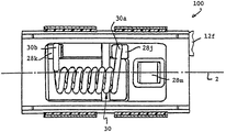
28f ドーム部分
28m 固定接点プラットフォーム
28j,28k 溶接突起
Claims (15)
- モータ保護装置であって、
底壁部と、開放端部を形成している前記底壁部から上に延びていて、前記開放端部の少なくとも2つの対向側面上に一部を有する横方向にまた外側に延びるフランジと一緒に形成されている自由端部を有する側壁部と、スイッチ・チャンバとを有するハウジング部材と、
前記ハウジング部材に電気的に接続している前記スイッチ・チャンバ内に位置する可動接点を有するサーモスタットスイッチと、
前記フランジ上に位置していて、前記ハウジング部材の前記開放端部と整合している開口部を有するガスケットと、
第1および第2の間隔を置いた部分を含む蓋であって、各蓋の一部が前記ハウジングのフランジ部分および前記ガスケット上に収容できるタブと一緒に形成されている2つの対向側部を有し、前記ガスケットを通して前記フランジ部分にクランプ留めされていて、各蓋の一部が、前記ガスケットでカバーされたフランジ部分上に位置する面の表面と、前記蓋が前記ガスケットでカバーされたフランジ上に位置した場合に、前記スイッチ・チャンバ内に位置する凹状接点棚部を有し、前記棚部が相互に整合し、相互に向き合っていて、セラミック基板シートを形成していて、前記第1の蓋の部分が、固定接点部分および前記固定接点部分と係合し、また離脱するように移動することができる可動接点を有する蓋と、
対向する第1および第2の面の表面、および対向端部と一緒に形成されているセラミック基板と、前記基板の前記第1の面の表面上の各端部のところに形成されている電気的接点面と、前記第1の面の表面間上に配置されていて、前記第1の面の表面上の各端部のところで前記接触面に電気的に接触している電気抵抗材料と、各接点棚上に位置する前記セラミック基板の前記接触面と一緒に形成されているセラミック基板と、
前記接点棚部に前記セラミック基板を通して接触力を加えるために、前記ハウジング部材に取り付けられているスプリング・クリップとを備え、
前記セラミック基板が、前記サーモスタットスイッチと密接な熱結合で前記スイッチ・チャンバ内に配置されているモータ保護装置。 - 前記スプリング・クリップ部材が、2つの対向端部と一緒に形成されている本体部分と、中央に位置する力を加える部分とを有し、前記クリップ部材の前記対向端部が、前記接点棚部に前記基板の前記第2の面の表面と係合している前記力を加える部分を含む蓋の一部の各タブ上に収容されている、請求項1記載のモータ保護装置。
- 前記スプリング・クリップ部材の前記端部が、前記本体部分を含むほぼV形の部分内に曲がっていて、前記V形の部分が、その中に各蓋の一部のタブを収容することができる、請求項2記載のモータ保護装置。
- 前記スプリング・クリップ部材の各端部が自由端部を有し、固定タブが各端部から突き出ていて、そのため前記固定タブが前記自由端部から遠ざかる方向に延びていて、蓋の一部が、捕捉部分を形成している各蓋タブ内に形成されているカットアウトを有し、前記スプリング・クリップ部材の固定タブを前記蓋の一部に前記スプリング・クリップをロックするために各捕捉部分上に収容することができる、請求項3記載のモータ保護装置。
- さらに、前記セラミック基板シートのどちらかの側上の前記接点棚部から延びる側壁部を備える、請求項1記載のモータ保護装置。
- 固定電気接点が、前記第1の蓋の一部の固定接点部分上に装着されている、請求項1記載のモータ保護装置。
- 前記ハウジングの前記フランジが、上面および下面の表面を有し、前記ガスケットが前記フランジの両方の面の表面上に置くための曲がった部分を有する、請求項1記載のモータ保護装置。
- 前記ガスケットの前記曲がった部分が、前記ハウジングの側壁部に沿って設置するための延長部と一緒に形成されている、請求項7記載のモータ保護装置。
- モータ保護装置であって、
縦軸と、底壁部と、開放端部を形成している前記底壁部から上に延びていて、前記開放端部の少なくとも2つの対向側面上に一部を有する横方向にまた外側に延びるフランジと一緒に形成されている自由端部を有する側壁部と、スイッチ・チャンバとを有するハウジングと、
前記ハウジング部材に電気的に接続している前記スイッチ・チャンバ内に位置する可動接点を有するサーモスタットスイッチと、
前記フランジ上に位置していて、前記ハウジング部材の前記開放端部と整合している開口部を有するガスケットと、
前記ガスケット上に収容され、前記ハウジングに取り付けられている第1および第2の間隔を置いた部分を有する蓋であって、前記蓋の一部の少なくとも一方が、凹状の引っ込んだ部分を形成しているドームを有する部分と一緒に形成されている蓋と、
ほぼ螺旋形を有し、第1および第2の端部を有し、前記端部が各間隔を置いた蓋の一部に電気的に接続していて、前記螺旋形の部分が前記2つの蓋の一部の凹状の部分に収容されていて、そこから間隔を有する細長いヒータ素子とを備えるモータ保護装置。 - 前記凹状の部分を形成している前記蓋の一部の前記部分が、前記第1および第2の蓋の一部内を延びる、請求項9記載のモータ保護装置。
- 前記ドームが前記縦軸に沿って延びる、請求項10記載のモータ保護装置。
- 前記ドームが、一方の蓋の一部内に比較的短い縦方向の長さを有し、他の蓋の一部内に比較的長い縦方向の長さを有する、請求項11記載のモータ保護装置。
- 各蓋の一部が、前記ハウジングのフランジ部分上に設置することができ、前記ガスケットを通して前記フランジ部分にクランプされるタブと一緒に形成されている2つの対向側面を有する、請求項9記載のモータ保護装置。
- 各蓋の一部上に形成されているヒータ素子溶接突起を含む、請求項9記載のモータ保護装置。
- 前記ヒータ素子の前記螺旋部分が、前記縦軸にほぼ平行な方向に延びていて、前記ヒータ素子の前記端部がほぼ横方向に延びる、請求項14記載のモータ保護装置。
Applications Claiming Priority (2)
| Application Number | Priority Date | Filing Date | Title |
|---|---|---|---|
| US10/727,297 US6995647B2 (en) | 2003-12-03 | 2003-12-03 | Low current electric motor protector |
| US10/843,101 US7102481B2 (en) | 2003-12-03 | 2004-05-11 | Low current electric motor protector |
Publications (3)
| Publication Number | Publication Date |
|---|---|
| JP2005176594A true JP2005176594A (ja) | 2005-06-30 |
| JP2005176594A5 JP2005176594A5 (ja) | 2008-03-13 |
| JP4463088B2 JP4463088B2 (ja) | 2010-05-12 |
Family
ID=34468079
Family Applications (1)
| Application Number | Title | Priority Date | Filing Date |
|---|---|---|---|
| JP2004349509A Expired - Fee Related JP4463088B2 (ja) | 2003-12-03 | 2004-12-02 | 低電流電気モータ保護装置 |
Country Status (6)
| Country | Link |
|---|---|
| US (1) | US7102481B2 (ja) |
| EP (2) | EP1538652A3 (ja) |
| JP (1) | JP4463088B2 (ja) |
| KR (1) | KR100947519B1 (ja) |
| CN (1) | CN100456591C (ja) |
| BR (1) | BRPI0405304A (ja) |
Cited By (1)
| Publication number | Priority date | Publication date | Assignee | Title |
|---|---|---|---|---|
| US9030787B2 (en) | 2011-06-28 | 2015-05-12 | Uchiya Thermostat Co., Ltd. | Motor protector |
Families Citing this family (14)
| Publication number | Priority date | Publication date | Assignee | Title |
|---|---|---|---|---|
| US7326887B1 (en) * | 2006-12-13 | 2008-02-05 | Sensata Technologies, Inc. | Modified reset motor protector |
| CN102007561B (zh) * | 2008-04-18 | 2014-07-02 | 泰科电子日本合同会社 | 电路保护装置 |
| IT1392191B1 (it) * | 2008-12-12 | 2012-02-22 | Electrica Srl | Protettore termico per motori elettrici, in particolare per motori eletrici per compressori |
| EP2282320A1 (de) * | 2009-08-01 | 2011-02-09 | Limitor GmbH | Bimetall-Schnappscheibe |
| CN101895093B (zh) * | 2010-05-06 | 2012-07-25 | 舟山市定海区巨洋技术开发有限公司 | 船舶舾装数控切割机外力过载保护器 |
| CN103081051B (zh) | 2010-09-24 | 2015-12-16 | 埃伦贝格尔及珀恩斯根有限公司 | 微型安全开关 |
| DE102011108660B3 (de) * | 2011-06-28 | 2012-11-22 | Thermik Gerätebau GmbH | Selbsthaltender temperaturabhängiger Schalter |
| US9048048B2 (en) * | 2012-08-16 | 2015-06-02 | Uchiya Thermostat Co., Ltd. | Thermal protector |
| CN105225893A (zh) * | 2015-10-08 | 2016-01-06 | 常州市家虹包装有限公司 | 防松型保护器 |
| TWI571035B (zh) * | 2015-10-20 | 2017-02-11 | 財團法人成大研究發展基金會 | 回授能量型保護器可靠性之測試電路系統 |
| CN107270862B (zh) * | 2017-07-14 | 2019-04-30 | 杭州星帅尔电器股份有限公司 | 微型热保护器中发热丝平整度的检测方法 |
| CN107275134B (zh) * | 2017-07-14 | 2019-03-05 | 杭州星帅尔电器股份有限公司 | 微型热保护器的装配方法 |
| CN107248477B (zh) * | 2017-07-14 | 2019-03-05 | 杭州星帅尔电器股份有限公司 | 微型热保护器及其发热丝的安装方法 |
| CN118321763B (zh) * | 2024-06-11 | 2024-08-16 | 江苏亿诚环保设备制造有限公司 | 一种数控切割机外力过载保护器 |
Family Cites Families (27)
| Publication number | Priority date | Publication date | Assignee | Title |
|---|---|---|---|---|
| US3095486A (en) * | 1960-07-14 | 1963-06-25 | Texas Instruments Inc | Miniaturized printed circuit electrical switching device |
| US3430177A (en) * | 1966-12-30 | 1969-02-25 | Texas Instruments Inc | Miniature thermostatic switch |
| US3622930A (en) * | 1969-10-16 | 1971-11-23 | Texas Instruments Inc | Motor protector apparatus and method |
| US3753195A (en) * | 1972-09-20 | 1973-08-14 | Gen Electric | Thermostatic switch |
| US4015229A (en) * | 1975-01-10 | 1977-03-29 | Texas Instruments Incorporated | Thermally responsive switch |
| US4086558A (en) * | 1976-02-09 | 1978-04-25 | Texas Instruments Incorporated | Motor protector and system |
| US4136323A (en) * | 1977-06-01 | 1979-01-23 | Entremont John R D | Miniature motor protector |
| US4224591A (en) * | 1978-12-04 | 1980-09-23 | Texas Instruments Incorporated | Motor protector with metal housing and with preformed external heater thereon |
| US4399423A (en) * | 1982-03-29 | 1983-08-16 | Texas Instruments Incorporated | Miniature electric circuit protector |
| US4476452A (en) | 1982-09-27 | 1984-10-09 | Texas Instruments Incorporated | Motor protector |
| USD281240S (en) * | 1983-03-16 | 1985-11-05 | Portage Electric Products, Inc. | Housing for a thermostatic switch |
| US4490704A (en) * | 1983-09-14 | 1984-12-25 | Therm-O-Disc, Incorporated | Thermally responsive switching device |
| US4646195A (en) * | 1983-11-14 | 1987-02-24 | Texas Instruments Incorporated | Motor protector particularly suited for use with compressor motors |
| USD336072S (en) * | 1991-07-23 | 1993-06-01 | Portage Electric Product, Inc. | Housing for a thermostatic switch |
| US5206622A (en) * | 1992-04-10 | 1993-04-27 | Texas Instruments Incorporated | Protector device with improved bimetal contact assembly and method of making |
| DE4428226C1 (de) * | 1994-08-10 | 1995-10-12 | Thermik Geraetebau Gmbh | Temperaturwächter |
| US5808539A (en) * | 1996-10-10 | 1998-09-15 | Texas Instruments Incorporated | Temperature responsive snap acting control assembly, device using such assembly and method for making |
| DE69800228T2 (de) * | 1997-03-18 | 2001-01-04 | Texas Instruments Inc., Dallas | Niedrigpreisthermostat und Verfahren zu seiner Kalibrierung |
| DE19727197C2 (de) * | 1997-06-26 | 1999-10-21 | Marcel Hofsaess | Temperaturabhängiger Schalter mit Kontaktbrücke |
| US5936510A (en) * | 1998-05-22 | 1999-08-10 | Portage Electric Products, Inc. | Sealed case hold open thermostat |
| US6020807A (en) * | 1999-02-23 | 2000-02-01 | Portage Electric Products, Inc. | Sealed case hold open thermostat |
| JP4545354B2 (ja) * | 2001-04-23 | 2010-09-15 | アスモ株式会社 | モータ及び封止構造 |
| US6756876B2 (en) * | 2001-09-24 | 2004-06-29 | Texas Instruments Incorporated | Circuit interrupter and method |
| CN2505974Y (zh) * | 2001-10-25 | 2002-08-14 | 邵志成 | 改良温度感应控制结构的器具插座 |
| US6744345B2 (en) * | 2002-05-06 | 2004-06-01 | Cooper Technologies | Mid-range circuit breaker |
| KR200296482Y1 (ko) * | 2002-08-27 | 2002-11-23 | 텍사스 인스트루먼트 코리아 주식회사 | 밀봉 구조의 과부하 보호기 |
| JP2005108585A (ja) * | 2003-09-30 | 2005-04-21 | Alps Electric Co Ltd | 熱応動スイッチ |
-
2004
- 2004-05-11 US US10/843,101 patent/US7102481B2/en not_active Expired - Lifetime
- 2004-11-08 EP EP04256918A patent/EP1538652A3/en not_active Withdrawn
- 2004-11-08 EP EP07001741A patent/EP1791150B1/en not_active Expired - Lifetime
- 2004-11-30 BR BR0405304-4A patent/BRPI0405304A/pt not_active Application Discontinuation
- 2004-12-02 JP JP2004349509A patent/JP4463088B2/ja not_active Expired - Fee Related
- 2004-12-03 KR KR1020040100787A patent/KR100947519B1/ko not_active Expired - Fee Related
- 2004-12-03 CN CNB2004100983451A patent/CN100456591C/zh not_active Expired - Fee Related
Cited By (2)
| Publication number | Priority date | Publication date | Assignee | Title |
|---|---|---|---|---|
| US9030787B2 (en) | 2011-06-28 | 2015-05-12 | Uchiya Thermostat Co., Ltd. | Motor protector |
| DE112012002681B4 (de) * | 2011-06-28 | 2018-06-14 | Uchiya Thermostat Co., Ltd. | Motorschutzschalter |
Also Published As
| Publication number | Publication date |
|---|---|
| KR100947519B1 (ko) | 2010-03-12 |
| EP1538652A2 (en) | 2005-06-08 |
| EP1791150B1 (en) | 2010-12-08 |
| KR20050053513A (ko) | 2005-06-08 |
| EP1791150A1 (en) | 2007-05-30 |
| BRPI0405304A (pt) | 2005-08-30 |
| EP1538652A3 (en) | 2005-07-20 |
| CN1627586A (zh) | 2005-06-15 |
| JP4463088B2 (ja) | 2010-05-12 |
| US20050122205A1 (en) | 2005-06-09 |
| CN100456591C (zh) | 2009-01-28 |
| US7102481B2 (en) | 2006-09-05 |
Similar Documents
| Publication | Publication Date | Title |
|---|---|---|
| JP4463088B2 (ja) | 低電流電気モータ保護装置 | |
| US4476452A (en) | Motor protector | |
| US4399423A (en) | Miniature electric circuit protector | |
| US4701824A (en) | Protected refrigerator compressor motor systems and motor protectors therefor | |
| US5367279A (en) | Overcurrent protection device | |
| JP2777042B2 (ja) | サーモスイッチ | |
| EP0177652B1 (en) | Motor protector particularly suited for use with compressor motors | |
| JP2000243199A (ja) | 密閉ケース開放保持サーモスタット | |
| JPS626294B2 (ja) | ||
| US6995647B2 (en) | Low current electric motor protector | |
| US6833782B2 (en) | Bimetal snap disc thermostat with heaters | |
| JP2008153216A (ja) | 変更されたリセットモータプロテクタ | |
| US20240258053A1 (en) | Temperature-dependent switch | |
| US6483418B1 (en) | Creep acting miniature thermostatic electrical switch and thermostatic member used therewith | |
| AU2009296611B2 (en) | Miniature circuit breaker | |
| JPS63292542A (ja) | 消弧装置とその製作方法 | |
| US7109840B2 (en) | Protector for electrical apparatus | |
| JP3829882B2 (ja) | サーマルプロテクタ | |
| US4879805A (en) | Method for making a circuit interrupter device | |
| JP2002352685A (ja) | サーマルプロテクタ | |
| JPH11126552A (ja) | 測温素子付温度ヒューズ | |
| JP3992320B2 (ja) | サーマルプロテクタ | |
| JP2651002B2 (ja) | モータの過負荷保護装置 | |
| JPH02265139A (ja) | モータの過負荷保護装置 |
Legal Events
| Date | Code | Title | Description |
|---|---|---|---|
| A711 | Notification of change in applicant |
Free format text: JAPANESE INTERMEDIATE CODE: A711 Effective date: 20060731 |
|
| A521 | Written amendment |
Free format text: JAPANESE INTERMEDIATE CODE: A523 Effective date: 20061117 |
|
| A521 | Written amendment |
Free format text: JAPANESE INTERMEDIATE CODE: A523 Effective date: 20070523 |
|
| A621 | Written request for application examination |
Free format text: JAPANESE INTERMEDIATE CODE: A621 Effective date: 20070523 |
|
| A521 | Written amendment |
Free format text: JAPANESE INTERMEDIATE CODE: A523 Effective date: 20071210 |
|
| A711 | Notification of change in applicant |
Free format text: JAPANESE INTERMEDIATE CODE: A711 Effective date: 20080708 |
|
| A131 | Notification of reasons for refusal |
Free format text: JAPANESE INTERMEDIATE CODE: A131 Effective date: 20090929 |
|
| A601 | Written request for extension of time |
Free format text: JAPANESE INTERMEDIATE CODE: A601 Effective date: 20091211 |
|
| A602 | Written permission of extension of time |
Free format text: JAPANESE INTERMEDIATE CODE: A602 Effective date: 20091216 |
|
| A521 | Written amendment |
Free format text: JAPANESE INTERMEDIATE CODE: A523 Effective date: 20100122 |
|
| TRDD | Decision of grant or rejection written | ||
| A01 | Written decision to grant a patent or to grant a registration (utility model) |
Free format text: JAPANESE INTERMEDIATE CODE: A01 Effective date: 20100216 |
|
| A01 | Written decision to grant a patent or to grant a registration (utility model) |
Free format text: JAPANESE INTERMEDIATE CODE: A01 |
|
| A61 | First payment of annual fees (during grant procedure) |
Free format text: JAPANESE INTERMEDIATE CODE: A61 Effective date: 20100216 |
|
| FPAY | Renewal fee payment (event date is renewal date of database) |
Free format text: PAYMENT UNTIL: 20130226 Year of fee payment: 3 |
|
| R150 | Certificate of patent or registration of utility model |
Free format text: JAPANESE INTERMEDIATE CODE: R150 |
|
| FPAY | Renewal fee payment (event date is renewal date of database) |
Free format text: PAYMENT UNTIL: 20130226 Year of fee payment: 3 |
|
| FPAY | Renewal fee payment (event date is renewal date of database) |
Free format text: PAYMENT UNTIL: 20140226 Year of fee payment: 4 |
|
| R250 | Receipt of annual fees |
Free format text: JAPANESE INTERMEDIATE CODE: R250 |
|
| R250 | Receipt of annual fees |
Free format text: JAPANESE INTERMEDIATE CODE: R250 |
|
| LAPS | Cancellation because of no payment of annual fees |