JP2005220902A - 振動減衰デバイスを備えた冷却式ローターブレード - Google Patents
振動減衰デバイスを備えた冷却式ローターブレード Download PDFInfo
- Publication number
- JP2005220902A JP2005220902A JP2004357453A JP2004357453A JP2005220902A JP 2005220902 A JP2005220902 A JP 2005220902A JP 2004357453 A JP2004357453 A JP 2004357453A JP 2004357453 A JP2004357453 A JP 2004357453A JP 2005220902 A JP2005220902 A JP 2005220902A
- Authority
- JP
- Japan
- Prior art keywords
- damper
- rotor blade
- longitudinal
- channel
- airfoil
- Prior art date
- Legal status (The legal status is an assumption and is not a legal conclusion. Google has not performed a legal analysis and makes no representation as to the accuracy of the status listed.)
- Ceased
Links
- 238000001816 cooling Methods 0.000 title claims description 41
- 238000013016 damping Methods 0.000 title abstract description 7
- 230000001965 increasing effect Effects 0.000 claims description 3
- 239000011800 void material Substances 0.000 description 5
- 230000015556 catabolic process Effects 0.000 description 2
- 238000006731 degradation reaction Methods 0.000 description 2
- 238000009792 diffusion process Methods 0.000 description 2
- 238000007789 sealing Methods 0.000 description 2
- 238000011144 upstream manufacturing Methods 0.000 description 2
- 238000005452 bending Methods 0.000 description 1
- 230000000295 complement effect Effects 0.000 description 1
- 230000003292 diminished effect Effects 0.000 description 1
- 230000000763 evoking effect Effects 0.000 description 1
- 230000002349 favourable effect Effects 0.000 description 1
- 239000012530 fluid Substances 0.000 description 1
- 230000005484 gravity Effects 0.000 description 1
- 238000003754 machining Methods 0.000 description 1
- 238000000034 method Methods 0.000 description 1
- 238000012986 modification Methods 0.000 description 1
- 230000004048 modification Effects 0.000 description 1
- 238000000465 moulding Methods 0.000 description 1
- 230000007704 transition Effects 0.000 description 1
Images




Classifications
-
- F—MECHANICAL ENGINEERING; LIGHTING; HEATING; WEAPONS; BLASTING
- F01—MACHINES OR ENGINES IN GENERAL; ENGINE PLANTS IN GENERAL; STEAM ENGINES
- F01D—NON-POSITIVE DISPLACEMENT MACHINES OR ENGINES, e.g. STEAM TURBINES
- F01D5/00—Blades; Blade-carrying members; Heating, heat-insulating, cooling or antivibration means on the blades or the members
- F01D5/12—Blades
- F01D5/14—Form or construction
- F01D5/16—Form or construction for counteracting blade vibration
-
- F—MECHANICAL ENGINEERING; LIGHTING; HEATING; WEAPONS; BLASTING
- F01—MACHINES OR ENGINES IN GENERAL; ENGINE PLANTS IN GENERAL; STEAM ENGINES
- F01D—NON-POSITIVE DISPLACEMENT MACHINES OR ENGINES, e.g. STEAM TURBINES
- F01D5/00—Blades; Blade-carrying members; Heating, heat-insulating, cooling or antivibration means on the blades or the members
- F01D5/12—Blades
- F01D5/14—Form or construction
- F01D5/18—Hollow blades, i.e. blades with cooling or heating channels or cavities; Heating, heat-insulating or cooling means on blades
- F01D5/187—Convection cooling
-
- F—MECHANICAL ENGINEERING; LIGHTING; HEATING; WEAPONS; BLASTING
- F05—INDEXING SCHEMES RELATING TO ENGINES OR PUMPS IN VARIOUS SUBCLASSES OF CLASSES F01-F04
- F05D—INDEXING SCHEME FOR ASPECTS RELATING TO NON-POSITIVE-DISPLACEMENT MACHINES OR ENGINES, GAS-TURBINES OR JET-PROPULSION PLANTS
- F05D2250/00—Geometry
- F05D2250/70—Shape
- F05D2250/71—Shape curved
-
- Y—GENERAL TAGGING OF NEW TECHNOLOGICAL DEVELOPMENTS; GENERAL TAGGING OF CROSS-SECTIONAL TECHNOLOGIES SPANNING OVER SEVERAL SECTIONS OF THE IPC; TECHNICAL SUBJECTS COVERED BY FORMER USPC CROSS-REFERENCE ART COLLECTIONS [XRACs] AND DIGESTS
- Y10—TECHNICAL SUBJECTS COVERED BY FORMER USPC
- Y10S—TECHNICAL SUBJECTS COVERED BY FORMER USPC CROSS-REFERENCE ART COLLECTIONS [XRACs] AND DIGESTS
- Y10S416/00—Fluid reaction surfaces, i.e. impellers
- Y10S416/50—Vibration damping features
Landscapes
- Engineering & Computer Science (AREA)
- Mechanical Engineering (AREA)
- General Engineering & Computer Science (AREA)
- Turbine Rotor Nozzle Sealing (AREA)
- Structures Of Non-Positive Displacement Pumps (AREA)
Abstract
【解決手段】翼形部20は少なくとも一つの空隙40を有する。少なくとも一つの空隙40は側壁36,38間に配されており、しかもチャネル42は第1の壁部54および第2の壁部56によって形成される。チャネル42内に選択的に収容されるダンパー24は、第1の支持面80、第2の支持面82、前方面76、および後方面78を含み、それら全ては長手方向に延在する。上記面の少なくとも一つはチャネル42内で長手方向延在流路92を形成する形状となっている。流路92は、少なくとも一つの面に沿った長手方向における冷却空気の移動を可能にするよう、少なくとも一つの面の長さに沿って方向付けられた流動方向を有する。ダンパー24は長手方向に延在するアーチ形中心線71を持つ。
【選択図】図3
Description
12 ディスク
14 ローターブレード
16 凹部
17 回転中心線
18 根部
20 翼形部
22 プラットフォーム
24 ダンパー
25 放射状中心線
26 流路
28 基端
30 先端
32 前縁
34 後縁
36 圧力側壁
38 吸引側壁
40 空隙
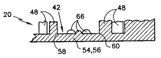
42 チャネル
44 第1の空隙部
46 第2の空隙部
48 柱脚
49 リブ
50 ポート
52 後方縁部
54 第1の壁部
56 第2の壁部
57 開口
58 第1の長手方向延在縁部
59 根部側面
60 第2の長手方向延在縁部
66 隆起部
68 蛇行流路
70 ヘッド
71 アーチ形中心線
72 本体
76 前方面
78 後方面
80,82 支持面
81 ヘッド端部
83 先端部
84 シール面
86 収れん部
88,90 蛇行流路
92 長手方向延在流路
94 長手方向延在溝
96 冷却開口
Claims (19)
- ローターアセンブリ用のローターブレードであって、
根部と、
基端と先端との間にわたる長さ、第1の側壁、第2の側壁、前記側壁間に配された少なくとも一つの空隙、ならびに第1の壁部および第2の壁部によって形成されたチャネルを有する翼形部と、
前記チャネル内に選択的に収容されるダンパーと、を具備し、
前記ダンパーは、第1の支持面、第2の支持面、前方面、および後方面を有する本体を含み、それら全ては長手方向に延在し、
前記面の少なくとも一つは前記チャネル内で長手方向に延在する流路を形成する形状となっており、かつ前記流路は、前記少なくとも一つの面に沿った長手方向における冷却空気の移動を可能にするよう、前記少なくとも一つの面の前記長さに沿って方向付けられた流動方向を有することを特徴とするローターブレード。 - 前記少なくとも一つの面は少なくとも一つの溝を含むような形状となっており、かつ前記溝は前記チャネル内に長手方向に延在する流路を形成することを特徴とする請求項1に記載のローターブレード。
- 前記ダンパー本体は第1の長手方向端部および第2の長手方向端部を含み、前記少なくとも一つの溝は実質的に前記本体の前記長手方向端部間に延在していることを特徴とする請求項2に記載のローターブレード。
- 前記面は、長手方向に延在する複数の溝を含む形状となっていることを特徴とする請求項2に記載のローターブレード。
- 前記第1の支持面および前記第2の支持面の一方あるいは両方は、長手方向に延在する溝を含む形状となっていることを特徴とする請求項4に記載のローターブレード。
- 前記第1の支持面および前記第2の支持面の一方あるいは両方は、長手方向に延在する溝を含む形状となっており、かつ各溝は前記チャネル内で長手方向に延在する流路を形成することを特徴とする請求項1に記載のローターブレード。
- 前記ダンパー本体は第1の長手方向端部および第2の長手方向端部を含み、かつ前記少なくとも一つの溝は実質的に前記本体の前記長手方向端部間に延在していることを特徴とする請求項6に記載のローターブレード。
- 前記ダンパー本体は、第1の長手方向端部、第2の長手方向端部、および長手方向に延在するアーチ形中心線を備えることを特徴とする請求項1に記載のローターブレード。
- 前記アーチ形中心線は、長手方向端部間で曲率が増大することを特徴とする請求項9に記載のローターブレード。
- 前記ダンパー本体の前記第1の長手方向端部は前記翼形部の前記基端に隣接して配置されていると共に、前記ダンパー本体の前記第2の長手方向端部は前記翼形部の前記先端に隣接して配置されており、かつ前記アーチ形中心線は、前記第1の長手方向端部から前記第2の長手方向端部に向かう方向に曲率が増大することを特徴とする請求項9に記載のローターブレード。
- ローターアセンブリ用のローターブレードであって、
根部と、
基端と先端との間にわたる長さ、第1の側壁、第2の側壁、前記側壁間に配された少なくとも一つの空隙、ならびに第1の壁部および第2の壁部によって形成されたチャネルを有する翼形部と、
前記チャネル内に選択的に収容されるダンパーと、を具備し、
前記ダンパーは、第1の支持面、第2の支持面、前方面、および後方面を有する本体を含み、それら全ては長手方向に延在し、
前記ダンパー本体はさらに、第1の長手方向端部、第2の長手方向端部、および長手方向に延在するアーチ形中心線を有することを特徴とするローターブレード。 - 前記アーチ形中心線は、長手方向端部間で曲率が増大することを特徴とする請求項11に記載のローターブレード。
- 前記ダンパー本体の前記第1の長手方向端部は前記翼形部の前記基端に隣接して配置されていると共に、前記ダンパー本体の前記第2の長手方向端部は前記翼形部の前記先端に隣接して配置されており、かつ前記アーチ形中心線は、前記第1の長手方向端部から前記第2の長手方向端部に向かう方向に曲率が増大することを特徴とする請求項12に記載のローターブレード。
- 第1の支持面と、
第2の支持面と、
前方面と、
後方面と、を具備し、
前記面の少なくとも一つは、少なくとも一つの長手方向延在溝を含むような形状となっていることを特徴とするローターブレードダンパー。 - 第1の長手方向端部と、
第2の長手方向端部と、をさらに具備し、
前記少なくとも一つの長手方向延在溝は、実質的に前記長手方向端部間に延在することを特徴とする請求項14に記載のローターブレードダンパー。 - 前記面は、複数の長手方向延在溝を含むような形状となっていることを特徴とする請求項15に記載のローターブレードダンパー。
- 前記第1の支持面および前記第2の支持面の一方または両方は、長手方向延在溝を含むような形状となっていることを特徴とする請求項14に記載のローターブレード。
- 前記ダンパーは、第1の長手方向端部、第2の長手方向端部、および長手方向に延在するアーチ形中心線を備えることを特徴とする請求項14に記載のローターブレードダンパー。
- 前記アーチ形中心線は、長手方向端部間で曲率が増大することを特徴とする請求項18に記載のローターブレードダンパー。
Applications Claiming Priority (1)
| Application Number | Priority Date | Filing Date | Title |
|---|---|---|---|
| US10/771,587 US7125225B2 (en) | 2004-02-04 | 2004-02-04 | Cooled rotor blade with vibration damping device |
Publications (1)
| Publication Number | Publication Date |
|---|---|
| JP2005220902A true JP2005220902A (ja) | 2005-08-18 |
Family
ID=34679363
Family Applications (1)
| Application Number | Title | Priority Date | Filing Date |
|---|---|---|---|
| JP2004357453A Ceased JP2005220902A (ja) | 2004-02-04 | 2004-12-09 | 振動減衰デバイスを備えた冷却式ローターブレード |
Country Status (10)
| Country | Link |
|---|---|
| US (1) | US7125225B2 (ja) |
| EP (1) | EP1561901B1 (ja) |
| JP (1) | JP2005220902A (ja) |
| KR (1) | KR100701545B1 (ja) |
| AU (1) | AU2004240224B2 (ja) |
| CA (1) | CA2487490A1 (ja) |
| IL (1) | IL166634A0 (ja) |
| NO (1) | NO20050623L (ja) |
| SG (1) | SG113614A1 (ja) |
| TW (1) | TWI256436B (ja) |
Cited By (5)
| Publication number | Priority date | Publication date | Assignee | Title |
|---|---|---|---|---|
| JP2008261326A (ja) * | 2007-04-10 | 2008-10-30 | General Electric Co <Ge> | ダンパ構成付きタービンブレード |
| CN102089498A (zh) * | 2008-07-10 | 2011-06-08 | 西门子公司 | 用于燃气涡轮机的涡轮机叶片和用于制造这样的涡轮机叶片的型芯 |
| JP2012077746A (ja) * | 2010-09-30 | 2012-04-19 | General Electric Co <Ge> | タービンロータブレードのプラットフォーム領域を冷却するための装置及び方法 |
| JP2014152765A (ja) * | 2013-02-13 | 2014-08-25 | Mitsubishi Heavy Ind Ltd | 回転機械翼 |
| US9488066B2 (en) | 2010-12-22 | 2016-11-08 | Mitsubishi Hitachi Power Systems, Ltd. | Turbine vane of steam turbine and steam turbine |
Families Citing this family (55)
| Publication number | Priority date | Publication date | Assignee | Title |
|---|---|---|---|---|
| US7549844B2 (en) * | 2006-08-24 | 2009-06-23 | Siemens Energy, Inc. | Turbine airfoil cooling system with bifurcated and recessed trailing edge exhaust channels |
| US9133715B2 (en) * | 2006-09-20 | 2015-09-15 | United Technologies Corporation | Structural members in a pedestal array |
| GB2450934B (en) | 2007-07-13 | 2009-10-07 | Rolls Royce Plc | A Component with a damping filler |
| US8267662B2 (en) * | 2007-12-13 | 2012-09-18 | General Electric Company | Monolithic and bi-metallic turbine blade dampers and method of manufacture |
| GB0808840D0 (en) | 2008-05-15 | 2008-06-18 | Rolls Royce Plc | A compound structure |
| GB2462102B (en) | 2008-07-24 | 2010-06-16 | Rolls Royce Plc | An aerofoil sub-assembly, an aerofoil and a method of making an aerofoil |
| US8079813B2 (en) * | 2009-01-19 | 2011-12-20 | Siemens Energy, Inc. | Turbine blade with multiple trailing edge cooling slots |
| GB0901235D0 (en) | 2009-01-27 | 2009-03-11 | Rolls Royce Plc | An article with a filler |
| GB0901318D0 (en) | 2009-01-28 | 2009-03-11 | Rolls Royce Plc | A method of joining plates of material to form a structure |
| US8172541B2 (en) * | 2009-02-27 | 2012-05-08 | General Electric Company | Internally-damped airfoil and method therefor |
| US8052391B1 (en) * | 2009-03-25 | 2011-11-08 | Florida Turbine Technologies, Inc. | High temperature turbine rotor blade |
| US8070450B1 (en) * | 2009-04-20 | 2011-12-06 | Florida Turbine Technologies, Inc. | High temperature turbine rotor blade |
| GB201009216D0 (en) | 2010-06-02 | 2010-07-21 | Rolls Royce Plc | Rotationally balancing a rotating part |
| GB2485831B (en) | 2010-11-26 | 2012-11-21 | Rolls Royce Plc | A method of manufacturing a component |
| US8944141B2 (en) | 2010-12-22 | 2015-02-03 | United Technologies Corporation | Drill to flow mini core |
| US9403208B2 (en) | 2010-12-30 | 2016-08-02 | United Technologies Corporation | Method and casting core for forming a landing for welding a baffle inserted in an airfoil |
| EP2535515A1 (en) * | 2011-06-16 | 2012-12-19 | Siemens Aktiengesellschaft | Rotor blade root section with cooling passage and method for supplying cooling fluid to a rotor blade |
| US8807945B2 (en) * | 2011-06-22 | 2014-08-19 | United Technologies Corporation | Cooling system for turbine airfoil including ice-cream-cone-shaped pedestals |
| US20130052036A1 (en) * | 2011-08-30 | 2013-02-28 | General Electric Company | Pin-fin array |
| US9249675B2 (en) * | 2011-08-30 | 2016-02-02 | General Electric Company | Pin-fin array |
| US8882461B2 (en) * | 2011-09-12 | 2014-11-11 | Honeywell International Inc. | Gas turbine engines with improved trailing edge cooling arrangements |
| US9279331B2 (en) * | 2012-04-23 | 2016-03-08 | United Technologies Corporation | Gas turbine engine airfoil with dirt purge feature and core for making same |
| US9267380B2 (en) * | 2012-04-24 | 2016-02-23 | United Technologies Corporation | Airfoil including loose damper |
| US8915718B2 (en) | 2012-04-24 | 2014-12-23 | United Technologies Corporation | Airfoil including damper member |
| US9296039B2 (en) | 2012-04-24 | 2016-03-29 | United Technologies Corporation | Gas turbine engine airfoil impingement cooling |
| US9404369B2 (en) | 2012-04-24 | 2016-08-02 | United Technologies Corporation | Airfoil having minimum distance ribs |
| US9181806B2 (en) | 2012-04-24 | 2015-11-10 | United Technologies Corporation | Airfoil with powder damper |
| US9470095B2 (en) | 2012-04-24 | 2016-10-18 | United Technologies Corporation | Airfoil having internal lattice network |
| US9133712B2 (en) | 2012-04-24 | 2015-09-15 | United Technologies Corporation | Blade having porous, abradable element |
| US9249668B2 (en) | 2012-04-24 | 2016-02-02 | United Technologies Corporation | Airfoil with break-way, free-floating damper member |
| US9243502B2 (en) | 2012-04-24 | 2016-01-26 | United Technologies Corporation | Airfoil cooling enhancement and method of making the same |
| US9121286B2 (en) | 2012-04-24 | 2015-09-01 | United Technologies Corporation | Airfoil having tapered buttress |
| US9074482B2 (en) | 2012-04-24 | 2015-07-07 | United Technologies Corporation | Airfoil support method and apparatus |
| US9175570B2 (en) | 2012-04-24 | 2015-11-03 | United Technologies Corporation | Airfoil including member connected by articulated joint |
| US9790801B2 (en) * | 2012-12-27 | 2017-10-17 | United Technologies Corporation | Gas turbine engine component having suction side cutback opening |
| EP2806106A1 (de) * | 2013-05-23 | 2014-11-26 | MTU Aero Engines GmbH | Turbomaschinenschaufel mit einem Impulskörper |
| US9765625B2 (en) | 2013-05-23 | 2017-09-19 | MTU Aero Engines AG | Turbomachine blade |
| US10557354B2 (en) * | 2013-08-28 | 2020-02-11 | United Technologies Corporation | Gas turbine engine airfoil crossover and pedestal rib cooling arrangement |
| US9732617B2 (en) | 2013-11-26 | 2017-08-15 | General Electric Company | Cooled airfoil trailing edge and method of cooling the airfoil trailing edge |
| US10914320B2 (en) * | 2014-01-24 | 2021-02-09 | Raytheon Technologies Corporation | Additive manufacturing process grown integrated torsional damper mechanism in gas turbine engine blade |
| US20160333699A1 (en) * | 2014-01-30 | 2016-11-17 | United Technologies Corporation | Trailing edge cooling pedestal configuration for a gas turbine engine airfoil |
| US10364684B2 (en) * | 2014-05-29 | 2019-07-30 | General Electric Company | Fastback vorticor pin |
| US20160169004A1 (en) * | 2014-12-15 | 2016-06-16 | United Technologies Corporation | Cooling passages for gas turbine engine component |
| DE102015226653A1 (de) | 2015-12-23 | 2017-06-29 | Siemens Aktiengesellschaft | Turbinenschaufel für eine thermische Strömungsmaschine |
| US10132168B2 (en) * | 2016-03-14 | 2018-11-20 | United Technologies Corporation | Airfoil |
| US10508552B2 (en) * | 2016-04-11 | 2019-12-17 | United Technologies Corporation | Internally cooled airfoil |
| US10436048B2 (en) * | 2016-08-12 | 2019-10-08 | General Electric Comapny | Systems for removing heat from turbine components |
| US11168566B2 (en) * | 2016-12-05 | 2021-11-09 | MTU Aero Engines AG | Turbine blade comprising a cavity with wall surface discontinuities and process for the production thereof |
| US10563520B2 (en) | 2017-03-31 | 2020-02-18 | Honeywell International Inc. | Turbine component with shaped cooling pins |
| US10774653B2 (en) | 2018-12-11 | 2020-09-15 | Raytheon Technologies Corporation | Composite gas turbine engine component with lattice structure |
| US11371358B2 (en) | 2020-02-19 | 2022-06-28 | General Electric Company | Turbine damper |
| EP3875735A1 (en) * | 2020-03-05 | 2021-09-08 | Siemens Aktiengesellschaft | Aerofoil for a gas turbine |
| US11352902B2 (en) * | 2020-08-27 | 2022-06-07 | Aytheon Technologies Corporation | Cooling arrangement including alternating pedestals for gas turbine engine components |
| US11739645B2 (en) | 2020-09-30 | 2023-08-29 | General Electric Company | Vibrational dampening elements |
| KR102488973B1 (ko) | 2021-01-11 | 2023-01-13 | 두산에너빌리티 주식회사 | 터빈용 에어포일 및 이를 포함하는 터빈 |
Family Cites Families (8)
| Publication number | Priority date | Publication date | Assignee | Title |
|---|---|---|---|---|
| CH494896A (de) * | 1968-08-09 | 1970-08-15 | Sulzer Ag | Halterung von Laufschaufeln im Rotor einer Turbomaschine |
| US5156528A (en) * | 1991-04-19 | 1992-10-20 | General Electric Company | Vibration damping of gas turbine engine buckets |
| US5516260A (en) * | 1994-10-07 | 1996-05-14 | General Electric Company | Bonded turbine airfuel with floating wall cooling insert |
| US5558497A (en) | 1995-07-31 | 1996-09-24 | United Technologies Corporation | Airfoil vibration damping device |
| US5820343A (en) | 1995-07-31 | 1998-10-13 | United Technologies Corporation | Airfoil vibration damping device |
| JPH1047004A (ja) | 1996-07-30 | 1998-02-17 | Mitsubishi Heavy Ind Ltd | 回転流体機械の動翼 |
| US6402470B1 (en) * | 1999-10-05 | 2002-06-11 | United Technologies Corporation | Method and apparatus for cooling a wall within a gas turbine engine |
| EP1136651A1 (de) | 2000-03-22 | 2001-09-26 | Siemens Aktiengesellschaft | Kühlsystem für eine Turbinenschaufel |
-
2004
- 2004-02-04 US US10/771,587 patent/US7125225B2/en not_active Expired - Lifetime
- 2004-11-09 CA CA002487490A patent/CA2487490A1/en not_active Abandoned
- 2004-11-22 TW TW093135897A patent/TWI256436B/zh not_active IP Right Cessation
- 2004-12-09 JP JP2004357453A patent/JP2005220902A/ja not_active Ceased
- 2004-12-13 KR KR1020040104677A patent/KR100701545B1/ko not_active Expired - Fee Related
- 2004-12-17 AU AU2004240224A patent/AU2004240224B2/en not_active Ceased
-
2005
- 2005-02-01 IL IL16663405A patent/IL166634A0/xx unknown
- 2005-02-03 SG SG200500637A patent/SG113614A1/en unknown
- 2005-02-04 EP EP05250651.6A patent/EP1561901B1/en not_active Expired - Lifetime
- 2005-02-04 NO NO20050623A patent/NO20050623L/no not_active Application Discontinuation
Cited By (7)
| Publication number | Priority date | Publication date | Assignee | Title |
|---|---|---|---|---|
| JP2008261326A (ja) * | 2007-04-10 | 2008-10-30 | General Electric Co <Ge> | ダンパ構成付きタービンブレード |
| CN102089498A (zh) * | 2008-07-10 | 2011-06-08 | 西门子公司 | 用于燃气涡轮机的涡轮机叶片和用于制造这样的涡轮机叶片的型芯 |
| JP2011527398A (ja) * | 2008-07-10 | 2011-10-27 | シーメンス アクティエンゲゼルシャフト | ガスタービンのためのタービンブレードまたはベーンならびにその内部の製造のための成型コア |
| CN102089498B (zh) * | 2008-07-10 | 2014-01-01 | 西门子公司 | 用于燃气涡轮机的涡轮机叶片和用于制造这样的涡轮机叶片的型芯 |
| JP2012077746A (ja) * | 2010-09-30 | 2012-04-19 | General Electric Co <Ge> | タービンロータブレードのプラットフォーム領域を冷却するための装置及び方法 |
| US9488066B2 (en) | 2010-12-22 | 2016-11-08 | Mitsubishi Hitachi Power Systems, Ltd. | Turbine vane of steam turbine and steam turbine |
| JP2014152765A (ja) * | 2013-02-13 | 2014-08-25 | Mitsubishi Heavy Ind Ltd | 回転機械翼 |
Also Published As
| Publication number | Publication date |
|---|---|
| EP1561901B1 (en) | 2015-06-24 |
| US7125225B2 (en) | 2006-10-24 |
| US20050169754A1 (en) | 2005-08-04 |
| EP1561901A2 (en) | 2005-08-10 |
| TW200526864A (en) | 2005-08-16 |
| EP1561901A3 (en) | 2009-04-15 |
| AU2004240224A1 (en) | 2005-08-18 |
| IL166634A0 (en) | 2006-01-15 |
| NO20050623D0 (no) | 2005-02-04 |
| CA2487490A1 (en) | 2005-08-04 |
| AU2004240224B2 (en) | 2007-02-08 |
| KR20050079212A (ko) | 2005-08-09 |
| KR100701545B1 (ko) | 2007-03-30 |
| SG113614A1 (en) | 2005-08-29 |
| TWI256436B (en) | 2006-06-11 |
| NO20050623L (no) | 2005-08-05 |
Similar Documents
| Publication | Publication Date | Title |
|---|---|---|
| JP2005220902A (ja) | 振動減衰デバイスを備えた冷却式ローターブレード | |
| JP4035131B2 (ja) | 振動減衰デバイスを備えた冷却式ローターブレード | |
| JP4035130B2 (ja) | 振動減衰デバイスを備えた冷却式ローターブレード | |
| JP4901186B2 (ja) | タービン用冷却システム | |
| JP4035129B2 (ja) | 振動減衰デバイスを備えた冷却式ローターブレード | |
| EP0757160B1 (en) | Airfoil vibration damping device | |
| EP1602801B1 (en) | Rotor blade with a stick damper | |
| JP2005337258A (ja) | ロータブレード | |
| AU2004240227B8 (en) | Cooled rotor blade with vibration damping device |
Legal Events
| Date | Code | Title | Description |
|---|---|---|---|
| A521 | Request for written amendment filed |
Free format text: JAPANESE INTERMEDIATE CODE: A821 Effective date: 20050518 |
|
| RD02 | Notification of acceptance of power of attorney |
Free format text: JAPANESE INTERMEDIATE CODE: A7422 Effective date: 20050518 |
|
| RD04 | Notification of resignation of power of attorney |
Free format text: JAPANESE INTERMEDIATE CODE: A7424 Effective date: 20050805 |
|
| A131 | Notification of reasons for refusal |
Free format text: JAPANESE INTERMEDIATE CODE: A131 Effective date: 20070522 |
|
| A521 | Request for written amendment filed |
Free format text: JAPANESE INTERMEDIATE CODE: A523 Effective date: 20070725 |
|
| A131 | Notification of reasons for refusal |
Free format text: JAPANESE INTERMEDIATE CODE: A131 Effective date: 20080108 |
|
| A521 | Request for written amendment filed |
Free format text: JAPANESE INTERMEDIATE CODE: A523 Effective date: 20080111 |
|
| A131 | Notification of reasons for refusal |
Free format text: JAPANESE INTERMEDIATE CODE: A131 Effective date: 20080304 |
|
| A521 | Request for written amendment filed |
Free format text: JAPANESE INTERMEDIATE CODE: A523 Effective date: 20080311 |
|
| A01 | Written decision to grant a patent or to grant a registration (utility model) |
Free format text: JAPANESE INTERMEDIATE CODE: A01 Effective date: 20080408 |
|
| A045 | Written measure of dismissal of application [lapsed due to lack of payment] |
Free format text: JAPANESE INTERMEDIATE CODE: A045 Effective date: 20080826 |