JP2005225748A - Method for producing ceramic body and firing tool - Google Patents
Method for producing ceramic body and firing tool Download PDFInfo
- Publication number
- JP2005225748A JP2005225748A JP2004376473A JP2004376473A JP2005225748A JP 2005225748 A JP2005225748 A JP 2005225748A JP 2004376473 A JP2004376473 A JP 2004376473A JP 2004376473 A JP2004376473 A JP 2004376473A JP 2005225748 A JP2005225748 A JP 2005225748A
- Authority
- JP
- Japan
- Prior art keywords
- thin
- buffer member
- ceramic body
- heat
- firing
- Prior art date
- Legal status (The legal status is an assumption and is not a legal conclusion. Google has not performed a legal analysis and makes no representation as to the accuracy of the status listed.)
- Withdrawn
Links
Images


Classifications
-
- C—CHEMISTRY; METALLURGY
- C04—CEMENTS; CONCRETE; ARTIFICIAL STONE; CERAMICS; REFRACTORIES
- C04B—LIME, MAGNESIA; SLAG; CEMENTS; COMPOSITIONS THEREOF, e.g. MORTARS, CONCRETE OR LIKE BUILDING MATERIALS; ARTIFICIAL STONE; CERAMICS; REFRACTORIES; TREATMENT OF NATURAL STONE
- C04B37/00—Joining burned ceramic articles with other burned ceramic articles or other articles by heating
- C04B37/003—Joining burned ceramic articles with other burned ceramic articles or other articles by heating by means of an interlayer consisting of a combination of materials selected from glass, or ceramic material with metals, metal oxides or metal salts
- C04B37/005—Joining burned ceramic articles with other burned ceramic articles or other articles by heating by means of an interlayer consisting of a combination of materials selected from glass, or ceramic material with metals, metal oxides or metal salts consisting of glass or ceramic material
-
- B—PERFORMING OPERATIONS; TRANSPORTING
- B28—WORKING CEMENT, CLAY, OR STONE
- B28B—SHAPING CLAY OR OTHER CERAMIC COMPOSITIONS; SHAPING SLAG; SHAPING MIXTURES CONTAINING CEMENTITIOUS MATERIAL, e.g. PLASTER
- B28B11/00—Apparatus or processes for treating or working the shaped or preshaped articles
- B28B11/24—Apparatus or processes for treating or working the shaped or preshaped articles for curing, setting or hardening
- B28B11/243—Setting, e.g. drying, dehydrating or firing ceramic articles
-
- C—CHEMISTRY; METALLURGY
- C04—CEMENTS; CONCRETE; ARTIFICIAL STONE; CERAMICS; REFRACTORIES
- C04B—LIME, MAGNESIA; SLAG; CEMENTS; COMPOSITIONS THEREOF, e.g. MORTARS, CONCRETE OR LIKE BUILDING MATERIALS; ARTIFICIAL STONE; CERAMICS; REFRACTORIES; TREATMENT OF NATURAL STONE
- C04B35/00—Shaped ceramic products characterised by their composition; Ceramics compositions; Processing powders of inorganic compounds preparatory to the manufacturing of ceramic products
- C04B35/622—Forming processes; Processing powders of inorganic compounds preparatory to the manufacturing of ceramic products
- C04B35/626—Preparing or treating the powders individually or as batches ; preparing or treating macroscopic reinforcing agents for ceramic products, e.g. fibres; mechanical aspects section B
- C04B35/62605—Treating the starting powders individually or as mixtures
- C04B35/62645—Thermal treatment of powders or mixtures thereof other than sintering
- C04B35/62655—Drying, e.g. freeze-drying, spray-drying, microwave or supercritical drying
-
- C—CHEMISTRY; METALLURGY
- C04—CEMENTS; CONCRETE; ARTIFICIAL STONE; CERAMICS; REFRACTORIES
- C04B—LIME, MAGNESIA; SLAG; CEMENTS; COMPOSITIONS THEREOF, e.g. MORTARS, CONCRETE OR LIKE BUILDING MATERIALS; ARTIFICIAL STONE; CERAMICS; REFRACTORIES; TREATMENT OF NATURAL STONE
- C04B35/00—Shaped ceramic products characterised by their composition; Ceramics compositions; Processing powders of inorganic compounds preparatory to the manufacturing of ceramic products
- C04B35/622—Forming processes; Processing powders of inorganic compounds preparatory to the manufacturing of ceramic products
- C04B35/64—Burning or sintering processes
-
- F—MECHANICAL ENGINEERING; LIGHTING; HEATING; WEAPONS; BLASTING
- F27—FURNACES; KILNS; OVENS; RETORTS
- F27D—DETAILS OR ACCESSORIES OF FURNACES, KILNS, OVENS OR RETORTS, IN SO FAR AS THEY ARE OF KINDS OCCURRING IN MORE THAN ONE KIND OF FURNACE
- F27D5/00—Supports, screens or the like for the charge within the furnace
-
- C—CHEMISTRY; METALLURGY
- C04—CEMENTS; CONCRETE; ARTIFICIAL STONE; CERAMICS; REFRACTORIES
- C04B—LIME, MAGNESIA; SLAG; CEMENTS; COMPOSITIONS THEREOF, e.g. MORTARS, CONCRETE OR LIKE BUILDING MATERIALS; ARTIFICIAL STONE; CERAMICS; REFRACTORIES; TREATMENT OF NATURAL STONE
- C04B2235/00—Aspects relating to ceramic starting mixtures or sintered ceramic products
- C04B2235/60—Aspects relating to the preparation, properties or mechanical treatment of green bodies or pre-forms
- C04B2235/602—Making the green bodies or pre-forms by moulding
- C04B2235/6025—Tape casting, e.g. with a doctor blade
-
- C—CHEMISTRY; METALLURGY
- C04—CEMENTS; CONCRETE; ARTIFICIAL STONE; CERAMICS; REFRACTORIES
- C04B—LIME, MAGNESIA; SLAG; CEMENTS; COMPOSITIONS THEREOF, e.g. MORTARS, CONCRETE OR LIKE BUILDING MATERIALS; ARTIFICIAL STONE; CERAMICS; REFRACTORIES; TREATMENT OF NATURAL STONE
- C04B2235/00—Aspects relating to ceramic starting mixtures or sintered ceramic products
- C04B2235/70—Aspects relating to sintered or melt-casted ceramic products
- C04B2235/96—Properties of ceramic products, e.g. mechanical properties such as strength, toughness, wear resistance
- C04B2235/9607—Thermal properties, e.g. thermal expansion coefficient
-
- C—CHEMISTRY; METALLURGY
- C04—CEMENTS; CONCRETE; ARTIFICIAL STONE; CERAMICS; REFRACTORIES
- C04B—LIME, MAGNESIA; SLAG; CEMENTS; COMPOSITIONS THEREOF, e.g. MORTARS, CONCRETE OR LIKE BUILDING MATERIALS; ARTIFICIAL STONE; CERAMICS; REFRACTORIES; TREATMENT OF NATURAL STONE
- C04B2235/00—Aspects relating to ceramic starting mixtures or sintered ceramic products
- C04B2235/70—Aspects relating to sintered or melt-casted ceramic products
- C04B2235/96—Properties of ceramic products, e.g. mechanical properties such as strength, toughness, wear resistance
- C04B2235/963—Surface properties, e.g. surface roughness
-
- C—CHEMISTRY; METALLURGY
- C04—CEMENTS; CONCRETE; ARTIFICIAL STONE; CERAMICS; REFRACTORIES
- C04B—LIME, MAGNESIA; SLAG; CEMENTS; COMPOSITIONS THEREOF, e.g. MORTARS, CONCRETE OR LIKE BUILDING MATERIALS; ARTIFICIAL STONE; CERAMICS; REFRACTORIES; TREATMENT OF NATURAL STONE
- C04B2237/00—Aspects relating to ceramic laminates or to joining of ceramic articles with other articles by heating
- C04B2237/02—Aspects relating to interlayers, e.g. used to join ceramic articles with other articles by heating
- C04B2237/04—Ceramic interlayers
- C04B2237/06—Oxidic interlayers
- C04B2237/068—Oxidic interlayers based on refractory oxides, e.g. zirconia
-
- C—CHEMISTRY; METALLURGY
- C04—CEMENTS; CONCRETE; ARTIFICIAL STONE; CERAMICS; REFRACTORIES
- C04B—LIME, MAGNESIA; SLAG; CEMENTS; COMPOSITIONS THEREOF, e.g. MORTARS, CONCRETE OR LIKE BUILDING MATERIALS; ARTIFICIAL STONE; CERAMICS; REFRACTORIES; TREATMENT OF NATURAL STONE
- C04B2237/00—Aspects relating to ceramic laminates or to joining of ceramic articles with other articles by heating
- C04B2237/30—Composition of layers of ceramic laminates or of ceramic or metallic articles to be joined by heating, e.g. Si substrates
- C04B2237/32—Ceramic
- C04B2237/34—Oxidic
- C04B2237/341—Silica or silicates
-
- C—CHEMISTRY; METALLURGY
- C04—CEMENTS; CONCRETE; ARTIFICIAL STONE; CERAMICS; REFRACTORIES
- C04B—LIME, MAGNESIA; SLAG; CEMENTS; COMPOSITIONS THEREOF, e.g. MORTARS, CONCRETE OR LIKE BUILDING MATERIALS; ARTIFICIAL STONE; CERAMICS; REFRACTORIES; TREATMENT OF NATURAL STONE
- C04B2237/00—Aspects relating to ceramic laminates or to joining of ceramic articles with other articles by heating
- C04B2237/30—Composition of layers of ceramic laminates or of ceramic or metallic articles to be joined by heating, e.g. Si substrates
- C04B2237/32—Ceramic
- C04B2237/34—Oxidic
- C04B2237/343—Alumina or aluminates
-
- C—CHEMISTRY; METALLURGY
- C04—CEMENTS; CONCRETE; ARTIFICIAL STONE; CERAMICS; REFRACTORIES
- C04B—LIME, MAGNESIA; SLAG; CEMENTS; COMPOSITIONS THEREOF, e.g. MORTARS, CONCRETE OR LIKE BUILDING MATERIALS; ARTIFICIAL STONE; CERAMICS; REFRACTORIES; TREATMENT OF NATURAL STONE
- C04B2237/00—Aspects relating to ceramic laminates or to joining of ceramic articles with other articles by heating
- C04B2237/30—Composition of layers of ceramic laminates or of ceramic or metallic articles to be joined by heating, e.g. Si substrates
- C04B2237/32—Ceramic
- C04B2237/34—Oxidic
- C04B2237/345—Refractory metal oxides
- C04B2237/346—Titania or titanates
-
- C—CHEMISTRY; METALLURGY
- C04—CEMENTS; CONCRETE; ARTIFICIAL STONE; CERAMICS; REFRACTORIES
- C04B—LIME, MAGNESIA; SLAG; CEMENTS; COMPOSITIONS THEREOF, e.g. MORTARS, CONCRETE OR LIKE BUILDING MATERIALS; ARTIFICIAL STONE; CERAMICS; REFRACTORIES; TREATMENT OF NATURAL STONE
- C04B2237/00—Aspects relating to ceramic laminates or to joining of ceramic articles with other articles by heating
- C04B2237/30—Composition of layers of ceramic laminates or of ceramic or metallic articles to be joined by heating, e.g. Si substrates
- C04B2237/32—Ceramic
- C04B2237/34—Oxidic
- C04B2237/345—Refractory metal oxides
- C04B2237/348—Zirconia, hafnia, zirconates or hafnates
-
- C—CHEMISTRY; METALLURGY
- C04—CEMENTS; CONCRETE; ARTIFICIAL STONE; CERAMICS; REFRACTORIES
- C04B—LIME, MAGNESIA; SLAG; CEMENTS; COMPOSITIONS THEREOF, e.g. MORTARS, CONCRETE OR LIKE BUILDING MATERIALS; ARTIFICIAL STONE; CERAMICS; REFRACTORIES; TREATMENT OF NATURAL STONE
- C04B2237/00—Aspects relating to ceramic laminates or to joining of ceramic articles with other articles by heating
- C04B2237/30—Composition of layers of ceramic laminates or of ceramic or metallic articles to be joined by heating, e.g. Si substrates
- C04B2237/32—Ceramic
- C04B2237/36—Non-oxidic
- C04B2237/365—Silicon carbide
-
- C—CHEMISTRY; METALLURGY
- C04—CEMENTS; CONCRETE; ARTIFICIAL STONE; CERAMICS; REFRACTORIES
- C04B—LIME, MAGNESIA; SLAG; CEMENTS; COMPOSITIONS THEREOF, e.g. MORTARS, CONCRETE OR LIKE BUILDING MATERIALS; ARTIFICIAL STONE; CERAMICS; REFRACTORIES; TREATMENT OF NATURAL STONE
- C04B2237/00—Aspects relating to ceramic laminates or to joining of ceramic articles with other articles by heating
- C04B2237/30—Composition of layers of ceramic laminates or of ceramic or metallic articles to be joined by heating, e.g. Si substrates
- C04B2237/32—Ceramic
- C04B2237/36—Non-oxidic
- C04B2237/368—Silicon nitride
-
- C—CHEMISTRY; METALLURGY
- C04—CEMENTS; CONCRETE; ARTIFICIAL STONE; CERAMICS; REFRACTORIES
- C04B—LIME, MAGNESIA; SLAG; CEMENTS; COMPOSITIONS THEREOF, e.g. MORTARS, CONCRETE OR LIKE BUILDING MATERIALS; ARTIFICIAL STONE; CERAMICS; REFRACTORIES; TREATMENT OF NATURAL STONE
- C04B2237/00—Aspects relating to ceramic laminates or to joining of ceramic articles with other articles by heating
- C04B2237/50—Processing aspects relating to ceramic laminates or to the joining of ceramic articles with other articles by heating
- C04B2237/56—Using constraining layers before or during sintering
- C04B2237/562—Using constraining layers before or during sintering made of alumina or aluminates
-
- C—CHEMISTRY; METALLURGY
- C04—CEMENTS; CONCRETE; ARTIFICIAL STONE; CERAMICS; REFRACTORIES
- C04B—LIME, MAGNESIA; SLAG; CEMENTS; COMPOSITIONS THEREOF, e.g. MORTARS, CONCRETE OR LIKE BUILDING MATERIALS; ARTIFICIAL STONE; CERAMICS; REFRACTORIES; TREATMENT OF NATURAL STONE
- C04B2237/00—Aspects relating to ceramic laminates or to joining of ceramic articles with other articles by heating
- C04B2237/50—Processing aspects relating to ceramic laminates or to the joining of ceramic articles with other articles by heating
- C04B2237/62—Forming laminates or joined articles comprising holes, channels or other types of openings
-
- C—CHEMISTRY; METALLURGY
- C04—CEMENTS; CONCRETE; ARTIFICIAL STONE; CERAMICS; REFRACTORIES
- C04B—LIME, MAGNESIA; SLAG; CEMENTS; COMPOSITIONS THEREOF, e.g. MORTARS, CONCRETE OR LIKE BUILDING MATERIALS; ARTIFICIAL STONE; CERAMICS; REFRACTORIES; TREATMENT OF NATURAL STONE
- C04B2237/00—Aspects relating to ceramic laminates or to joining of ceramic articles with other articles by heating
- C04B2237/50—Processing aspects relating to ceramic laminates or to the joining of ceramic articles with other articles by heating
- C04B2237/66—Forming laminates or joined articles showing high dimensional accuracy, e.g. indicated by the warpage
-
- C—CHEMISTRY; METALLURGY
- C04—CEMENTS; CONCRETE; ARTIFICIAL STONE; CERAMICS; REFRACTORIES
- C04B—LIME, MAGNESIA; SLAG; CEMENTS; COMPOSITIONS THEREOF, e.g. MORTARS, CONCRETE OR LIKE BUILDING MATERIALS; ARTIFICIAL STONE; CERAMICS; REFRACTORIES; TREATMENT OF NATURAL STONE
- C04B2237/00—Aspects relating to ceramic laminates or to joining of ceramic articles with other articles by heating
- C04B2237/50—Processing aspects relating to ceramic laminates or to the joining of ceramic articles with other articles by heating
- C04B2237/70—Forming laminates or joined articles comprising layers of a specific, unusual thickness
- C04B2237/702—Forming laminates or joined articles comprising layers of a specific, unusual thickness of one or more of the constraining layers
-
- C—CHEMISTRY; METALLURGY
- C04—CEMENTS; CONCRETE; ARTIFICIAL STONE; CERAMICS; REFRACTORIES
- C04B—LIME, MAGNESIA; SLAG; CEMENTS; COMPOSITIONS THEREOF, e.g. MORTARS, CONCRETE OR LIKE BUILDING MATERIALS; ARTIFICIAL STONE; CERAMICS; REFRACTORIES; TREATMENT OF NATURAL STONE
- C04B2237/00—Aspects relating to ceramic laminates or to joining of ceramic articles with other articles by heating
- C04B2237/50—Processing aspects relating to ceramic laminates or to the joining of ceramic articles with other articles by heating
- C04B2237/70—Forming laminates or joined articles comprising layers of a specific, unusual thickness
- C04B2237/704—Forming laminates or joined articles comprising layers of a specific, unusual thickness of one or more of the ceramic layers or articles
-
- C—CHEMISTRY; METALLURGY
- C04—CEMENTS; CONCRETE; ARTIFICIAL STONE; CERAMICS; REFRACTORIES
- C04B—LIME, MAGNESIA; SLAG; CEMENTS; COMPOSITIONS THEREOF, e.g. MORTARS, CONCRETE OR LIKE BUILDING MATERIALS; ARTIFICIAL STONE; CERAMICS; REFRACTORIES; TREATMENT OF NATURAL STONE
- C04B2237/00—Aspects relating to ceramic laminates or to joining of ceramic articles with other articles by heating
- C04B2237/50—Processing aspects relating to ceramic laminates or to the joining of ceramic articles with other articles by heating
- C04B2237/86—Joining of two substrates at their largest surfaces, one surface being complete joined and covered, the other surface not, e.g. a small plate joined at it's largest surface on top of a larger plate
-
- Y—GENERAL TAGGING OF NEW TECHNOLOGICAL DEVELOPMENTS; GENERAL TAGGING OF CROSS-SECTIONAL TECHNOLOGIES SPANNING OVER SEVERAL SECTIONS OF THE IPC; TECHNICAL SUBJECTS COVERED BY FORMER USPC CROSS-REFERENCE ART COLLECTIONS [XRACs] AND DIGESTS
- Y02—TECHNOLOGIES OR APPLICATIONS FOR MITIGATION OR ADAPTATION AGAINST CLIMATE CHANGE
- Y02P—CLIMATE CHANGE MITIGATION TECHNOLOGIES IN THE PRODUCTION OR PROCESSING OF GOODS
- Y02P40/00—Technologies relating to the processing of minerals
- Y02P40/60—Production of ceramic materials or ceramic elements, e.g. substitution of clay or shale by alternative raw materials, e.g. ashes
Landscapes
- Engineering & Computer Science (AREA)
- Chemical & Material Sciences (AREA)
- Ceramic Engineering (AREA)
- Structural Engineering (AREA)
- Manufacturing & Machinery (AREA)
- Materials Engineering (AREA)
- Organic Chemistry (AREA)
- Inorganic Chemistry (AREA)
- Mechanical Engineering (AREA)
- Physics & Mathematics (AREA)
- Thermal Sciences (AREA)
- General Engineering & Computer Science (AREA)
- Furnace Charging Or Discharging (AREA)
Abstract
Description
本発明は、セラミックス体の製造方法、及びセラミックス体焼成用治具に関する。より詳しくは、いわゆるダイヤフラム構造を備えるセラミックス体に好適な製造方法及びそれに用いるセラミックス体焼成用治具に関する。 The present invention relates to a method for manufacturing a ceramic body and a ceramic body firing jig. More specifically, the present invention relates to a manufacturing method suitable for a ceramic body having a so-called diaphragm structure and a ceramic body firing jig used therefor.
各種電子部品にあっては、セラミックス製の基体が広く適用されており、その代表的なものとして、圧電/電歪膜型素子等に適用されるダイヤフラム構造の基体がある。 In various electronic parts, a ceramic substrate is widely used, and a typical example thereof is a substrate having a diaphragm structure applied to a piezoelectric / electrostrictive film type element or the like.
ダイヤフラム構造の基体は、厚肉部間に板状の薄肉部が支持され、薄肉部の下方又は上方に凹部又は空所を有する構造の基体であり、圧電/電歪膜型素子の場合には、この薄肉部が振動部として機能する。 A substrate having a diaphragm structure is a substrate having a structure in which a plate-like thin portion is supported between thick portions, and has a recess or a space below or above the thin portion. In the case of a piezoelectric / electrostrictive film type element, The thin portion functions as a vibrating portion.
ところで、各種電子部品に適用されるセラミックス製の基体は、近年、より薄く、より小さく、より複雑化することが求められる一方、焼成時の変形が問題となっており、焼成時の変形を防止する様々な試みがなされている。 By the way, ceramic substrates applied to various electronic components have recently been required to be thinner, smaller, and more complicated. On the other hand, deformation during firing has been a problem, and deformation during firing has been prevented. Various attempts have been made.
例えば、特許文献1には、焼成によって反り等の変形が発生したセラミックス体を、その上部に重りを載せた状態で、再度高温による加熱処理を行うことで、反り等の変形を矯正する方法が開示されている(例えば、特許文献1参照)。
For example,
しかし、この特許文献1に記載の製造方法は、2度加熱処理を要することから、エネルギー消費が非常に大きく、製品のコストを低減する上でも、大きな問題となっていた。また、一度変形したものを矯正するため、矯正後の基体には、少なからず応力が残留し、加えて、矯正工程が再度の加熱によるためセラミックス材料の粒成長、及び相変態を生じる。このため、矯正後のセラミックス製の基体は、強度、耐湿性等の点でも必ずしも十分なものではなかった。更に、重り板による加重のかけ方によっては、薄肉部に破損を生じることがあった。
However, since the manufacturing method described in
これに対して、焼成時においてセラミックスグリーンシートの反りを防ぐため、重量、面積及び単位面積当りの加重が、所定の関係を満たす重しを用いて、表面平滑性に優れた0.5mm以下の焼成板を形成せしめる方法が開示されている。また、脱脂の観点から5〜30%の気孔率の重しが開示されている(例えば、特許文献2参照)。 On the other hand, in order to prevent warping of the ceramic green sheet during firing, the weight, area, and weight per unit area are 0.5 mm or less excellent in surface smoothness using a weight that satisfies a predetermined relationship. A method for forming a fired plate is disclosed. Moreover, the porosity weight of 5 to 30% is disclosed from a viewpoint of degreasing (for example, refer patent document 2).
また、面積が400cm2以上で且つ厚さが0.4mm以下の焼成板を焼成する際の反り及びうねり抑制方法として、グリーンシートを多孔質アルミナシートで数層に挟み加重をかける方法が開示されている(例えば、特許文献3参照)。 Further, as a method for suppressing warpage and waviness when firing a fired plate having an area of 400 cm 2 or more and a thickness of 0.4 mm or less, a method of applying a load by sandwiching a green sheet between several layers with a porous alumina sheet is disclosed. (For example, refer to Patent Document 3).
しかし、特許文献2、3に記載の方法では、ダイヤフラム構造を備えるセラミックス体に適用することについて全く考慮されておらず、ダイヤフラム構造の薄肉部の変形について何ら解決法を開示していない。
However, in the methods described in
また、ダイヤフラム構造を備えるセラミックス体においては、特許文献2、3に開示された方法が対象とするようなサイズでなくても、その複雑な形状から反り及びうねりが発生する。更に、重し板により加重をかけながら再加熱する方法では、内側に撓んで変形した薄肉部はその変形を矯正することができない。加えて、両面に薄肉部が形成されているセラミックス体の反り及びうねりを矯正する場合には、変形の山側にある薄肉部の撓みが圧縮されて更に撓むため、二面間での撓み量の差が大きくなる。このため、薄肉部が湾曲した状態のまま各種素子に適用しているのが現状である。
Further, in a ceramic body having a diaphragm structure, warping and undulation occur from its complicated shape even if the size disclosed in
本発明は、上述の問題を解決すべくなされたものであり、その目的とするところは、ダイヤフラム構造を備えるセラミックス体において、その薄肉部の撓みが少ない所望形状のセラミックス体が得られる製造方法、及びそれに用いる焼成用治具を提供することにある。 The present invention has been made to solve the above-mentioned problems, and the object of the present invention is a manufacturing method in which a ceramic body having a diaphragm structure and a ceramic body having a desired shape with a small thickness portion is obtained. And providing a firing jig used therefor.
本発明者は、上述の問題を解決すべく鋭意検討したところ、ダイヤフラム構造における薄肉部の撓みや変形が以下のようにして生じることを見出した。ダイヤフラム構造を備える成形体を焼成する際には、最初、薄肉部が焼結してセラミックス体となった後も、厚肉部の焼結は進行中であり、厚肉部は収縮し続けている。従って、薄肉部は、厚肉部が焼成収縮する際に、既に大きな剛性を有しており、厚肉部の収縮に追従できない状態となっている。このため、当該薄肉部は、厚肉部の収縮により、空所側又はそれと反対側に撓み、ダイヤフラム構造を備えるセラミックス体の主な変形の原因となっていた。 As a result of intensive studies to solve the above-mentioned problems, the present inventor has found that the thin-walled portion of the diaphragm structure is bent or deformed as follows. When firing a molded body having a diaphragm structure, after the thin-walled portion is first sintered into a ceramic body, the thick-walled portion is still being sintered and the thick-walled portion continues to shrink. Yes. Therefore, the thin portion already has a large rigidity when the thick portion is fired and contracted, and is in a state where it cannot follow the contraction of the thick portion. For this reason, the thin-walled portion bends to the void side or the opposite side due to the contraction of the thick-walled portion, which is a main cause of deformation of the ceramic body having the diaphragm structure.
更に、熱緩衝部材を、薄肉部に接触あるいは非常に近接した非接触の状態で、薄肉部を覆う位置に配置して、ダイヤフラム構造の成形体を焼成することにより、薄肉部と厚肉部との焼結時間の較差が低減され、成形体全体がほぼ同じタイミングで焼結し、薄肉部の撓みが減少することを見出し、本発明を完成するに至った。ここで、焼結時間とは、各々の部位の焼結が開始してから完了するまでに要する時間を意味する。 Further, the heat buffer member is disposed in a position that covers the thin portion in a non-contact state in contact with or very close to the thin portion, and the molded article having the diaphragm structure is fired, thereby reducing the thin portion and the thick portion. It was found that the difference in the sintering time was reduced, the entire molded body was sintered at substantially the same timing, and the bending of the thin wall portion was reduced, and the present invention was completed. Here, the sintering time means the time required from the start to the completion of sintering of each part.
即ち、本発明は、厚肉部と板状の薄肉部とを備え、該薄肉部と該厚肉部とにより凹部又は空所が形成されるように該厚肉部と該薄肉部が配置されたダイヤフラム構造を有する成形体を焼成するセラミックス体の製造方法であって、該成形体の該薄肉部と接触又は非接触の状態で該薄肉部を覆う位置に熱緩衝部材を配置して焼成を開始することを含むセラミックス体の製造方法を提供するものである。 That is, the present invention includes a thick part and a plate-like thin part, and the thick part and the thin part are arranged so that a recess or a void is formed by the thin part and the thick part. A method of manufacturing a ceramic body for firing a molded body having a diaphragm structure, wherein a thermal buffer member is disposed at a position covering the thin-walled portion in contact with or not in contact with the thin-walled portion of the molded body. A method of manufacturing a ceramic body including starting is provided.
本発明においては、熱緩衝部材として平板状のものを用い、前記成形体を挟持する位置に少なくとも2つの該熱緩衝部材を配置して焼成を開始することが好ましい。 In the present invention, it is preferable to use a flat plate as the heat buffer member, arrange at least two heat buffer members at positions where the molded body is sandwiched, and start firing.
また、本発明においては、成形体が、空所を挟んで対向する2つの薄肉部を備えるダイヤフラム構造を有し、熱緩衝部材を、2つの薄肉部を覆う位置に各々配置して焼成を開始することが好ましい。 Further, in the present invention, the molded body has a diaphragm structure having two thin portions opposed to each other with a space therebetween, and the heat buffer member is disposed at a position covering the two thin portions, and firing is started. It is preferable to do.
ここで、本明細書において「熱緩衝部材」とは、薄肉部及び厚肉部が大気に開放された状態で焼成した場合に比べ、薄肉部及び厚肉部の任意の単位体積が任意の単位時間に受け取る熱量の差を低減する作用を有する部材を意味する。 Here, in the present specification, the term “thermal buffer member” means that any unit volume of the thin part and the thick part is an arbitrary unit as compared with the case where the thin part and the thick part are fired in a state where the thin part and the thick part are open to the atmosphere. The member which has the effect | action which reduces the difference of the calorie | heat amount received in time is meant.
もっとも、本発明において熱緩衝部材は、その単位面積当りの熱容量が、熱緩衝部材を配置する薄肉部の単位面積当りの熱容量以上のものを用いることが好ましい。 However, in the present invention, it is preferable to use a heat buffer member whose heat capacity per unit area is equal to or greater than the heat capacity per unit area of the thin portion where the heat buffer member is disposed.
また、薄肉部と厚肉部との単位面積当りの熱容量差と、熱緩衝部材の単位面積当りの熱容量(Cb)との関係が、
0≦((Cb−Cs)/Cs)×100≦300 …1
であることが更に好ましい。なお、(Cs)、(Cb)は各々、以下の式により求められる値を意味する。
Cb=(ρb×db×tb) …2
(式2において、Cb:熱緩衝部材の単位面積当りの熱容量、ρb:熱緩衝部材の比熱、tb:熱緩衝部材厚さ、db:熱緩衝部材の密度)
Cs=(ρs×ds×(t2−t1)) …3
(式3において、Cs:薄肉部の単位面積当りの熱容量、ρs:成形体の比熱、t1:成形体の薄肉部厚さ、t2:成形体の厚肉部厚さ(但し、成形体が空所を挟んで対向する2つの薄肉部を持つ場合、t2は全厚さの半分とする)、ds:成形体の密度)
The relationship between the heat capacity difference per unit area between the thin wall portion and the thick wall portion and the heat capacity per unit area of the heat buffer member (C b ) is
0 ≦ ((C b −C s ) / C s ) × 100 ≦ 300... 1
More preferably. Note that (C s ) and (C b ) each mean a value obtained by the following equation.
C b = (ρ b × d b × t b ) 2
(In the
C s = (ρ s × d s × (t 2 −t 1 )) 3
(In
また、本発明において、薄肉部と熱緩衝部材との間隔が熱緩衝部材の厚さ以下であることが好ましい。更に、この間隔が、厚肉部の厚さと薄肉部の厚さの差以下であることが好ましい。なお、本発明において、表面に凸部が形成された成形体又は熱緩衝部材を用い、該凸部が熱緩衝部材又は成形体と接触するように熱緩衝部材を配置することにより、薄肉部の少なくとも一部と熱緩衝部材とを非接触の状態としてもよい。この場合、凸部を形成する手段は、薄膜を形成させる手段であれば特に制限はないが、量産性の観点からするとスクリーン印刷法で形成するのが好ましい。 Moreover, in this invention, it is preferable that the space | interval of a thin part and a heat buffer member is below the thickness of a heat buffer member. Furthermore, it is preferable that this space | interval is below the difference of the thickness of a thick part, and the thickness of a thin part. In the present invention, by using a molded body or a thermal buffer member having a convex portion formed on the surface, and arranging the thermal buffer member so that the convex portion is in contact with the thermal buffer member or the molded body, At least a portion and the heat buffering member may be in a non-contact state. In this case, the means for forming the convex portion is not particularly limited as long as it is a means for forming a thin film, but it is preferably formed by a screen printing method from the viewpoint of mass productivity.
本発明においては、熱緩衝部材として、気孔率1〜70%の多孔質体で構成されるものを用いることが好ましい。 In the present invention, it is preferable to use a heat buffer member made of a porous body having a porosity of 1 to 70%.
また、熱緩衝部材が成形体を加圧した状態で前記焼成を行うことも好ましい。また、薄肉部の上面が実質的に水平となるように成形体を配置し、薄肉部の上面に熱緩衝部材を配置することにより加圧することも好ましい。 Moreover, it is also preferable to perform the firing in a state where the heat buffer member pressurizes the molded body. Moreover, it is also preferable to pressurize by arrange | positioning a molded object so that the upper surface of a thin part may become substantially horizontal, and arrange | positioning a heat buffer member on the upper surface of a thin part.
上述のように当該熱緩衝部材に重し部材としての機能を兼備させてもよく、その場合には、熱緩衝部材上に配置されたスペーサーと、スペーサーを介して該熱緩衝部材の上方に配置された加重調節部材が存在する状態で焼成を開始すことが更に好ましい。この際、スペーサーが、焼成の開始から終了までの間、成形体、又はその成形体から焼成により形成されるセラミックス体、の上方に常に配置された状態とすることが更に好ましい。 As described above, the heat buffer member may be combined with a function as a weight member. In that case, a spacer disposed on the heat buffer member and a spacer disposed above the heat buffer member via the spacer. More preferably, firing is started in a state where the weight adjusting member is present. At this time, it is more preferable that the spacer is always disposed above the formed body or the ceramic body formed by firing from the formed body from the start to the end of firing.
このように成形体を加圧する加圧力は、単位体積当り1×10⁻⁴〜2×10⁻¹g/mm3となる圧力であることが好ましい。また、熱緩衝部材として、厚さ0.3〜10.0mmのものを用いることができる。 Thus, it is preferable that the applied pressure which pressurizes a molded object is a pressure used as 1 * 10 < -4 > -2 * 10 < -1 > g / mm < 3 > per unit volume. Further, a heat buffer member having a thickness of 0.3 to 10.0 mm can be used.
また、前記熱緩衝部材の、前記成形体と接触する面の単位接触面積当りの算術平均粗さ(Ra)が、0.1≦Ra75≦10.0μmであることが好ましく、熱緩衝部材の熱伝導率が、前記薄肉部の熱伝導率よりも大きいことも好ましい。また、本発明における成形体は、凹部又は空所が1つのものであってもよく、凹部又は空所が2以上のものであってもよい。 Moreover, it is preferable that arithmetic mean roughness (Ra) per unit contact area of the surface which contacts the said molded object of the said heat buffer member is 0.1 <= Ra75 <= 10.0micrometer, and heat of a heat buffer member is preferable. It is also preferable that the conductivity is larger than the thermal conductivity of the thin wall portion. In addition, the molded body in the present invention may have one concave portion or void, or may have two or more concave portions or voids.
また、本発明は、このような製造方法に好適な焼成用治具、即ち、多孔質セラミックスからなる熱緩衝部と、該熱緩衝部の一の面に配設されたスペーサーと、該スペーサーを介して、該熱緩衝部に対して非接触で配設される加重調節部とを備え、該熱緩衝部及び該加重調節部の間に空隙が保持されていることを特徴とする焼成用治具を提供するものである。 The present invention also provides a firing jig suitable for such a manufacturing method, that is, a thermal buffer portion made of porous ceramics, a spacer disposed on one surface of the thermal buffer portion, and the spacer. And a load adjusting unit disposed in a non-contact manner with respect to the heat buffer unit, and a gap is held between the heat buffer unit and the load adjusting unit. It provides tools.
本発明の焼成用治具においては、熱緩衝部が、気孔率1〜70%の多孔質体で構成されているものが好ましく、熱緩衝部が、厚さ0.3〜10.0mmであるものが好ましい。 In the firing jig of the present invention, it is preferable that the thermal buffer portion is composed of a porous body having a porosity of 1 to 70%, and the thermal buffer portion has a thickness of 0.3 to 10.0 mm. Those are preferred.
また、熱緩衝部の外面の少なくとも一部、即ち被焼成体と接触する面の単位接触面積当りの算術平均粗さ(Ra75)が、0.1≦Ra75≦10.0μmであることが好ましい。ここで、Ra75は、JIS’82に準拠した方法により、測定装置として、東京精密(株)SURFCOM480Aを用い、触針の先端半径5μm、先端角度60°材質ダイヤモンドとし、測定速度0.6mm/sec、カットオフ0.8mm、測定距離5mmの条件で得ることができる値である。 Moreover, it is preferable that arithmetic average roughness (Ra75) per unit contact area of at least a part of the outer surface of the thermal buffer portion, that is, the surface that contacts the fired body is 0.1 ≦ Ra75 ≦ 10.0 μm. Here, Ra75 is a method based on JIS'82, using Tokyo Seimitsu Co., Ltd., SURFCOM 480A as a measuring device, with a stylus tip radius of 5 μm and a tip angle of 60 ° diamond, and a measurement speed of 0.6 mm / sec. , A value that can be obtained under conditions of a cutoff of 0.8 mm and a measurement distance of 5 mm.
本発明によれば、ダイヤフラム構造を備えるセラミックス体において、その薄肉部の撓みが少ない所望形状のセラミックス体が得られる製造方法を提供することができる。また、ダイヤフラム構造を含む各種形状のセラミックス体を焼成する際に、被焼成体に対し、適切なる加重を付与しながら、焼成時に発生するガスの抜けが良好で、得られるセラミックス体の破損、変形が極めて少ない焼成用治具を提供することができる。 ADVANTAGE OF THE INVENTION According to this invention, in the ceramic body provided with a diaphragm structure, the manufacturing method which can obtain the ceramic body of the desired shape with few bending of the thin part can be provided. Also, when firing ceramic bodies of various shapes including diaphragm structures, the gas generated during firing is good while giving appropriate weight to the body to be fired, and the resulting ceramic body is damaged or deformed. It is possible to provide a firing jig with extremely little.
以下、本発明の実施の形態を具体的に説明する。但し、本発明は、以下の記載に限定されて解釈されるものではなく、本発明の範囲を逸脱しない限りにおいて、当業者の知識に基づいて、種々の変更、修正、改良を加え得るものである。図1は、本発明の一の実施の形態を模式的に示す断面図である。 Hereinafter, embodiments of the present invention will be specifically described. However, the present invention is not construed as being limited to the following description, and various changes, modifications, and improvements can be added based on the knowledge of those skilled in the art without departing from the scope of the present invention. is there. FIG. 1 is a cross-sectional view schematically showing one embodiment of the present invention.
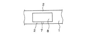
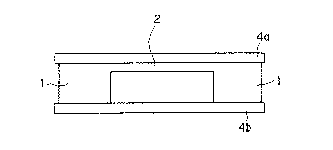
図1に示すように、本発明のセラミックス体の製造方法は、厚肉部1と板状の薄肉部2とを備え、薄肉部2と厚肉部1とにより凹部又は空所が形成されるように厚肉部1と薄肉部2が配置されたダイヤフラム構造を含む成形体3を焼成する工程を含み、薄肉部2に、好ましくは薄肉部の一の面全体、更に好ましくは薄肉部及び厚肉部で構成される一の面全体を、熱緩衝部材4が接触した状態で覆う位置に熱緩衝部材4を配置して焼成を行うものである。あるいは、熱緩衝部材4が薄肉部2の一部又は全部と非接触の状態で薄肉部2の一面全体、好ましくは薄肉部及び厚肉部で構成される一の面全体を覆う位置に熱緩衝部材4を配置して焼成を行うものである。なお、図1には、2つの厚肉部1とその間に配置された薄肉部2が示されているが、この厚肉部1は、各々独立したものでもよく、あるいは厚肉部1が例えばリング状になっており、図1において示された2つの厚肉部1がつながっているようなものでもよい。
As shown in FIG. 1, the method for manufacturing a ceramic body of the present invention includes a
これにより、薄肉部2の撓みが抑制された所望のダイヤフラム構造を有するセラミックス体が得られ、このようなセラミックス体は、薄肉部の撓みが抑制されることにより、例えば、HDD素子のように挟みこむ構造(例えば特開2001−320099号公報に記載されているような構造)を有し、高精度を要する部品として適用可能となり、圧電/電歪膜型素子等の電子部品に適用した際に所望の性能を発揮させることができる。ここで、特開2001−320099号公報の記載は、本願明細書の記載に含めるものとする。
As a result, a ceramic body having a desired diaphragm structure in which the bending of the
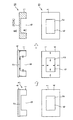
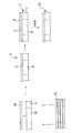
ここで、図面を用いて、本発明の製造方法の基本原理について説明する。図9は、厚肉部1間に板状の一の薄肉部2が支持され、薄肉部2の下方に凹部6を有するダイヤフラム構造の成形体を、薄肉部が直接大気に開放された状態で焼成する場合の成形体の挙動を示す説明図であり、図2は、同じダイヤフラム構造の成形体を、薄肉部に緩衝部材を接触させて焼成する場合(本発明の製造方法)の成形体の挙動を示す説明図である。
Here, the basic principle of the manufacturing method of the present invention will be described with reference to the drawings. FIG. 9 shows a diaphragm-shaped molded body in which one thin-
なお、各図で、矢印は、薄肉部及び厚肉部において主要な焼成収縮が起こっている状態を示し、斜線で示す領域は、焼結がほぼ完了し、セラミックス化した部位を示す。 In each figure, an arrow indicates a state where main firing shrinkage occurs in the thin-walled portion and the thick-walled portion, and a hatched region indicates a portion where the sintering is almost completed and converted into ceramic.
図9に示すように、薄肉部2と厚肉部1とを有するダイヤフラム構造の成形体3を、薄肉部2及び厚肉部1の何れも大気雰囲気に開放された状態で焼成した場合には、その厚みの差に起因して薄肉部2の焼結が先に完了する。そして、厚肉部1は、薄肉部2の焼結がほぼ終了してその大部分がセラミックス化した後も、まだ焼結の途上にある。このため、既に剛性の高い薄肉部2(斜線で示す)は、厚肉部1の収縮により応力がかかり、空所側Aか、もしくはその反対側Bに撓んだ状態で最終的な焼結が終了する。
As shown in FIG. 9, when a molded
これに対して、図2に示すようにして、同じダイヤフラム構造の成形体3を、薄肉部2に熱緩衝部材4を接触させて焼成した場合には、焼成雰囲気の熱が熱緩衝部材4を介して薄肉部2及び厚肉部1に伝わり、薄肉部2及び厚肉部1へ伝わる単位時間当りの熱量は大気から直接伝達される場合に比べ小さくなる。このため、当該熱緩衝部材4の熱容量を調整することで、薄肉部2の焼結の進行を、厚肉部1の焼結の進行に近づけることができ、更に熱緩衝部材の存在により伝達される熱量の局所的な偏重が抑制され、薄肉部2の撓みが抑制されたダイヤフラム構造のセラミックス体を得ることができる。
On the other hand, as shown in FIG. 2, when the molded
なお、熱緩衝部材4が薄肉部2に直接接触しなくてもこのような効果を得ることができる。これは、薄肉部2と熱緩衝部材4とが非接触であっても、放射によって熱緩衝部材4から薄肉部2へ熱エネルギーが伝わるためである。即ち、熱緩衝部材4が、薄肉部2の少なくとも一部と非接触の状態で薄肉部2を覆うように熱緩衝部材4を配置することによっても薄肉部2の焼結の進行を、厚肉部1の焼結の進行に近づけることができる。しかし、あまりに間隔が広くなると薄肉部2と熱緩衝部材4の間を空気が流れるため薄肉部表面や熱緩衝部材表面から熱エネルギーを損失してしまい、本発明の効果が十分に発揮されない。従って、熱緩衝部材4と薄肉部2との間隔は、0(即ち、接触状態)から熱緩衝部材の厚さ以下の範囲内であることが好ましく、0から熱緩衝部材の厚さの半分以下の範囲内であることが更に好ましい。また、熱緩衝部材4と薄肉部2との間隔が、厚肉部1と薄肉部2との厚さの差、即ち凹部6の厚さより大きいと、薄肉部2と凹部6を挟んで対向する位置に存在する物体の影響が、熱緩衝部材4の効果よりも大きくなる場合がある。従って、熱緩衝部材4と薄肉部2との間隔は厚肉部1と薄肉部2との厚さの差よりも小さいことが好ましい。
In addition, even if the
薄肉部2と非接触の状態で薄肉部2を覆う位置に熱緩衝部材4を配置する具体的な方法として、成形体3の一部の表面、好ましくは外周部の表面に凸部を設け、この凸部と接触した状態で薄肉部2を覆うように熱緩衝部4を配置する方法が挙げられる。即ち、凸部をスペーサーとして、薄肉部2と熱緩衝部材との間に所定の間隔を設ける方法が挙げられる。この場合、この凸部の高さがこの間隔に対応するようになる。熱緩衝部材4と薄肉部2との間隔が上述の好ましい範囲となるように凸部を設ける好ましい方法として、スクリーン印刷などの印刷により成形体に薄膜を形成して凸部とする方法が挙げられる。なお、凸部は、熱緩衝部材4に設けても同様の効果が得られる。また、成形体表面の外周部分を囲むように凸部を設けた場合は、空気の流れをほぼ遮断することができ、熱エネルギーの損失を抑制できるためよりよい。
As a specific method of disposing the
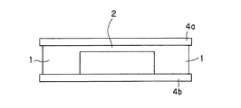
図3は、空所8を挟んで対向する2つの薄肉部2a、2bを備えるダイヤフラム構造を有する成形体を、両方の薄肉部に緩衝部材4a、4bを接触又は非常に近接した非接触の状態として焼成する場合の成形体の挙動を示す説明図である。(以下において、「直接接触」と記載しない限り、「接触」とは一部接触及び非常に近接した非接触の状態も含むものとする)
FIG. 3 shows a non-contact state in which a molded body having a diaphragm structure having two
本発明において、図3に示すように、熱緩衝部材4a、4bを、各薄肉部2a、2bに各々接触させた状態で焼成を開始することが好ましい。
In the present invention, as shown in FIG. 3, it is preferable to start firing in a state where the
成形体が2つの薄肉部2a、2bを有する場合には、図3に示すようにして、ダイヤフラム構造の成形体3を、両方の薄肉部2a、2bに緩衝部材4a、4bを接触させて焼成することにより、大気等の焼成雰囲気から、各薄肉部2a、2bへ伝達される単位時間当りの熱量が同様に小さくなり、各薄肉部2a、2bの焼結の進行を、厚肉部1の焼結の進行に近づかせることができるとともに、各薄肉部2a、2b間においても、焼結をほぼ同時に進行させることができる。また、両方の薄肉部に伝達される熱量の局所的な偏重が抑制される。このため、何れの薄肉部2a、2bについても、撓みが抑制されたダイヤフラム構造のセラミックス体を得ることができる。図3に示す形態においても、熱緩衝部材4a又は4bと薄肉部2b又は2aとの間隔が各々大きすぎると本発明の効果が小さくなりすぎる場合があるため、この間隔は0(即ち、接触状態)から熱緩衝部材4a又は4bの厚さ以下の範囲内であることが好ましく、0から熱緩衝部材4a又は4bの厚さの半分以下の範囲内であることが更に好ましい。更に、この間隔が、厚肉部1の厚さと薄肉部2a及び2bの合計の厚さとの差、即ち空所8の厚さより大きいと、例えば、熱緩衝部材4aの薄肉部2bに対する効果よりも、空所8を挟んで対向する薄肉部2aや熱緩衝部材4bの薄肉部2bに対する影響の方が大きくなる場合がある。従って、熱緩衝部材4a又は4bと薄肉部2b又は2aとの各々の間隔は、厚肉部1の厚さと薄肉部2a及び2bの合計の厚さとの差よりも小さいことが好ましい。
When the molded body has two
薄肉部2と厚肉部1の焼結完了時間の差を効果的に減少させるには、接触対象となる薄肉部2及び厚肉部1と同じかそれ以上の単位面積当りの熱容量を有する熱緩衝部材4を用いることが好ましい。熱容量が大きいものは熱緩衝部材に接する薄肉部の面に、任意の時期に、中でも焼成初期に、供給するエネルギー密度を小さくし、温度分布を狭くできるからである。
In order to effectively reduce the difference in the sintering completion time between the
更には、式3で求められる薄肉部と厚肉部との単位面積当りの熱容量差(Cs)と式2で求められる熱緩衝部材の単位面積当りの熱容量(Cb)との関係が、
0≦((Cb−Cs)/Cs)×100≦300 …1
であることが好ましい。
Cb=(ρb×db×tb) …2
(式2において、Cb:熱緩衝部材の単位面積当りの熱容量、ρb:熱緩衝部材の比熱、tb:熱緩衝部材厚さ、db:熱緩衝部材の密度)
Cs=(ρs×ds×(t2−t1)) …3
(式3において、Cs:薄肉部の単位面積当りの熱容量、ρs:成形体の比熱、t1:成形体の薄肉部厚さ、t2:成形体の厚肉部厚さ、ds:成形体の密度)
Furthermore, the relationship between the heat capacity difference per unit area (C s ) between the thin wall portion and the thick wall portion obtained by
0 ≦ ((C b −C s ) / C s ) × 100 ≦ 300... 1
It is preferable that
C b = (ρ b × d b × t b ) 2
(In the
C s = (ρ s × d s × (t 2 −t 1 )) 3
(In
また、本発明における熱緩衝部材4は、厚さを厚くすることで、単位面積当りの熱容量を大きくしてもよいが、厚さによらず材料の特性によって調製することが好ましい。
In addition, the
材料の特性によって調製することにより、成形体に加わる過度な加重を回避することができ、成形体3と熱緩衝部材4間の摩擦抵抗を低減するため、成形体3の焼成収縮の際に生じる寸法精度の歪を抑制することができる。また、後述するように熱緩衝部材が多孔質の場合には、この厚さを薄くすることにより、より脱脂が容易となる。
By adjusting according to the characteristics of the material, an excessive load applied to the molded body can be avoided, and the frictional resistance between the molded
具体的には、接触対象となる薄肉部を構成する材料より、比熱が大きな材料からなる熱緩衝部材を用いることが好ましく、例えば、表1に示すような材料の特性に基づいて、成形体の特性との関係から適宜選択することができる。例えば薄肉部及び厚肉部を構成する材料が、ジルコニアであれば、アルミナ、スピネル、マグネシア、ベリリア等からなる材料を用いることができ、薄肉部を構成する材料が、アルミナであれば、マグネシア、ベリリア等からなる材料を用いることができる。 Specifically, it is preferable to use a heat buffer member made of a material having a larger specific heat than the material constituting the thin portion to be contacted. For example, based on the characteristics of the material as shown in Table 1, It can select suitably from the relationship with a characteristic. For example, if the material constituting the thin-walled portion and the thick-walled portion is zirconia, a material made of alumina, spinel, magnesia, beryllia, etc. can be used, and if the material constituting the thin-walled portion is alumina, magnesia, A material made of beryllia or the like can be used.
また、本発明における熱緩衝部材4は、薄肉部2に更に均一に熱を伝えることが可能となる点で、熱伝導率が、薄肉部の熱伝導率よりも大きい熱緩衝部材が好ましく、熱伝導率が2.0(W/m・K)以上の材料からなる熱緩衝部材4が更に好ましい。
In addition, the
また、このような材料としては、例えば、アルミナ、スピネル、マグネシア、ベリリア等を挙げることができる。 Examples of such materials include alumina, spinel, magnesia, and beryllia.
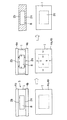
また、本発明における熱緩衝部材4は、焼成時に薄肉部2に均一に熱を伝え、成形体3の焼成ムラを抑制できる点で、図1に示すように、少なくとも、薄肉部2の外表面F1を含んで接触するものが好ましいが、薄肉部2及び厚肉部1で構成される一の外表面F2を含んで接触するものが更に好ましい。また、焼成時において成形体の薄肉部の撓みを低減するとともに成形体全体の変形をも抑制するためには、図4に示すように、熱緩衝部材として平板状のものを用い、少なくとも当該熱緩衝部材4a、4bの何れかと薄肉部2とを接触させながら、2つの熱緩衝部材4a、4bで成形体3を挟持した状態とすることが最も好ましい。
Further, the
また、熱緩衝部材が成形体を加圧した状態で前記焼成を行うことがセラミックス体全体の反りやうねりを抑制する点で好ましい。加圧する方法に特に制限はないが、例えば図1等に示すように、薄肉部2の上面が実質的に水平となるように成形体を配置し、薄肉部2の上面に前記熱緩衝部材を配置することにより加圧することが好ましい。ここで、実質的に水平とは、薄肉部の上面に配置された熱緩衝部材が自然落下しない程度に水平であることを意味し、薄肉部の上面が水平面に対して5°以内となる程度に水平であることが好ましい。
Moreover, it is preferable that the firing is performed in a state where the heat buffer member pressurizes the molded body in terms of suppressing warpage and undulation of the entire ceramic body. The method of pressurizing is not particularly limited. For example, as shown in FIG. 1 and the like, the molded body is arranged so that the upper surface of the
また、図3に示すように、成形体が、空所8を挟んで対向する2つの薄肉部2a、2bを備えるダイヤフラム構造を有する場合には、この2つの薄肉部の面が水平となるように成形体を配置し、この成形体全体を上下から挟持するように2つの熱緩衝部材4a、4bを配置することも好ましい。
Further, as shown in FIG. 3, when the molded body has a diaphragm structure including two
これにより、薄肉部2a、2bと厚肉部1との間、更には2つの薄肉部2aと2bとの間においても、焼結完了時間の較差を低減することができ、焼成時における薄肉部の撓みを低減することができる。また、2つの熱緩衝部材4a、4bにより、成形体3を、成形体上下面全体で挟持することで、当該薄肉部における撓みの低減に加え、成形体全体の反りやうねりといった変形をも抑制することができる。なお、薄肉部と熱緩衝部材が非接触の場合でも、直接接触する凸部に均等に圧力を加えることにより成形体全体の反りやうねりといった変形を抑制することができる。
Thereby, the difference in sintering completion time can be reduced between the
成形体を加圧する際の加圧力は、小さすぎると十分な効果が得られずに反り等が発生し、大きすぎると平面方向の焼成収縮に影響を及ぼして、平面方向の寸法歪みが発生したり、場合によっては成形体が割れてしまう。適切な加重量は成形体の体積に関係し、単位体積当り1×10⁻⁴〜2×10⁻¹g/mm3が好ましく、更に2×10-4〜1×10-1g/mm3が好ましく、特に単位体積当り1×10-3〜1×10-1g/mm3の加重量となる圧力であることが好ましい。 If the pressure applied to the molded body is too small, sufficient effects cannot be obtained and warping will occur, and if it is too large, it will affect the firing shrinkage in the plane direction, causing dimensional distortion in the plane direction. In some cases, the molded body is broken. The appropriate weight is related to the volume of the molded body, preferably 1 × 10 −4 to 2 × 10 −1 g / mm 3 per unit volume, and more preferably 2 × 10 −4 to 1 × 10 −1 g / mm 3. In particular, the pressure is preferably a pressure that gives a weight of 1 × 10 −3 to 1 × 10 −1 g / mm 3 per unit volume.
本発明において図1等に示す熱緩衝部材4は、成形体焼成時に、成形体中の有機成分が焼失して発生するガスを容易に外部へ解放でき、ガスの蓄積によるセラミックス体の破損を防止できるものが好ましい。具体的には、多孔質体で構成される熱緩衝部材を用いることが好ましく、更には、気孔率が1〜70%の多孔質体で構成されるものが好ましく、気孔率が1〜50%、特に1〜25%の多孔質体で構成されるものが更に好ましい。また、同様の点で、厚さが0.3〜10.0mmの熱緩衝部材4が好ましく、厚さが0.5〜5.0mmの熱緩衝部材4が更に好ましい。
In the present invention, the
また、熱緩衝部材4による圧力の調整は、単に熱緩衝部材の肉厚化によらず、図5(a)、(b)に示すように、多孔質セラミックスからなる熱緩衝部(熱緩衝部材4)と、その面に配設されたスペーサー21と、これを介して、熱緩衝部(又は熱緩衝部材4)に対して非接触で配設される加重調節部(又は加重調節部材22)とを備え、熱緩衝部(又は熱緩衝部材4)及び加重調節部(又は加重調節部材22)間に空隙23が保持されている焼成用治具25を用い、当該焼成用治具25を、少なくとも、成形体上面に配設することが好ましい。
In addition, the adjustment of the pressure by the
このような焼成用治具25を成形体上面に配設すると、加重調節部(又は加重調節部材22)の厚さ等を変更することにより成形体3に付加する加重を調整できるとともに、熱緩衝部(又は熱緩衝部材4)及び加重調節部(又は加重調節部材22)間に存する空隙23により、焼成時に薄肉部2a、2bから発生してくるガスの解放が確保される。また、スペーサー21の位置に特に制限はないが、スペーサーを配置することによる単位面積当りの熱容量の変化の影響を少なくするため、図5(a)、(b)に示すように、スペーサーを厚肉部上に配置することが好ましく、薄肉部から離れた位置に配置することが更に好ましい。薄肉部が複数ある場合には、薄肉部から実質的に等距離になるようにスペーサーを配置することも好ましい。
When such a
なお、当該焼成用治具25を用いる場合には、熱緩衝部(又は熱緩衝部材4)の寸法を成形体3への加重の観点から制限する必要はない。従って、加重調節部(又は加重調節部材22)の厚さ等を調製しながら、熱緩衝部(又は熱緩衝部材4)を薄肉化又は高気孔率化することで、成形体に対する所望の加重を確保し、且つ焼成時に薄肉部2から発生してくるガスを、より確実に外部へ開放することができる。また、当該焼成用治具25は、成形体3の下方に位置する薄肉部2aに用いることも有用である。この場合、成形体3の薄肉部2が、直接、セッター等の積載面と接することがなく、焼成時に薄肉部2から発生してくるガスの解放ルートが空隙23により確保されることとなる。この場合には、加重調節部(又は加重調節部材22)は、加重を調整する機能は有しないため、熱緩衝部(又は熱緩衝部材4)とスペーサーがあればこの効果を得ることができる。更に、当該焼成用治具25は、本発明の製造方法のみならず、シート状のセラミックス体、又は当該シート状のセラミックス体の積層体等、他の形状のセラミックス体を焼成する際にも、同様の効果を奏する。ここで、熱緩衝部(又は熱緩衝部材4)は、気孔率1〜70、更に1〜50%、特に1〜25%の多孔質体であることが好ましく、また、厚さが0.3〜10mmであることが好ましく、0.5〜5mmであることが好ましい。
In addition, when using the said baking jig |
また、スペーサーが、焼成の開始から終了までの間、成形体又はセラミックス体の上方に常に配置された状態とすることが好ましい。薄肉部が大きな板の場合に、板の周辺と中心部に荷重が均等にかかるようにし、それにより薄肉部の変形を抑えることができ、またこれにより成形体を確実に加圧することが可能となる。また、薄肉部と熱緩衝部が非接触の場合にも、直接接触する凸部に加重が均等にかかるようにすることにより薄肉部を含む成形体の変形を抑えることができる。焼成前にはスペーサーが成形体の上方に配置され、加重調節部が成形体を十分に加圧している状態であっても、収縮により成形体又は成形体から形成されるセラミックス体の上方の位置からスペーサーがずれてしまうと焼結中に加圧状態が変化し、スムーズな収縮を阻害する場合もあり、図5(a)、(b)に示すように常にスペーサーが成形体又はセラミックス体の垂直上方に存在することにより良好な製品寸法精度のセラミックス体を得ることができる。 Further, it is preferable that the spacer is always disposed above the formed body or the ceramic body from the start to the end of firing. When the thin-walled part is a large plate, the load is evenly applied to the periphery and center of the plate, so that deformation of the thin-walled part can be suppressed, and it is possible to pressurize the molded body reliably. Become. Further, even when the thin wall portion and the heat buffer portion are not in contact with each other, deformation of the molded body including the thin wall portion can be suppressed by applying an even weight to the directly contacting convex portion. Even before the firing, the spacer is arranged above the molded body, and the position above the ceramic body formed from the molded body or the molded body by shrinkage even when the weight adjusting part sufficiently pressurizes the molded body. If the spacer deviates from, the pressure state changes during sintering, and smooth shrinkage may be inhibited. As shown in FIGS. 5 (a) and 5 (b), the spacer is always formed of a molded body or ceramic body. A ceramic body with good product dimensional accuracy can be obtained by being present vertically above.
本発明において図1等に示す熱緩衝部材4としては、成形体3と熱緩衝部材4とが少なくとも一部で直接接触する場合において、成形体3と熱緩衝部材4間での摩擦抵抗を低減して、成形体3をできるだけ均等に焼成収縮させるために、成形体3との接触面、好ましくは熱緩衝部材の一面全体の算術平均粗さ(Ra75)が、0.1≦Ra75≦10.0μmであることが好ましく、更に0.1≦Ra75≦6.0μm、特に0.1≦Ra75≦3.0μmであることが好ましい。なお、本発明の焼成治具において、熱緩衝部と加重調節部とスペーサーとは一体化していてもよく、分解可能であってもよい。
In the present invention, the
本発明において、当該ダイヤフラム構造を備える成形体3は、例えばドクターブレード法、リバースロールコーター法、カレンダーロール法、鋳込み成形法、ホットプレス法、射出成形法、又は押出し成形法等により作製することができる。中でも、ドクターブレード法により作製された成形体は、精度がよく、薄い薄肉部2を有することができるため好ましい。
In the present invention, the molded
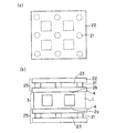
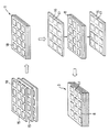
また、ドクターブレード法等のシート成形方法により成形された成形体を用いる場合には、図6及び図8に示すように、各成形方法で得た各グリーンシート15を、切断、打ち抜き等により、最終的な凹部6又は空所8に相当する大きさの貫通孔18を少なくとも1以上設けた後、積層して積層体11を作製し、この積層体11の貫通孔18が開口する上下面の少なくとも1の面に、薄肉部2を構成させるためのグリーンシート16を積層することにより、厚肉部1間に板状の薄肉部2が支持され、薄肉部2の下方又は上方に凹部6又は空所8のあるダイヤフラム構造を備える成形体3を得ることができる。なお、同様の方法で、凹部又は空所を1つのみ有する成形体を作製することもでき、図8に示すように複数の凹部又は空所を有する成形体を作製することもできる。また、複数の凹部又は空所を有する成形体の場合、異なる形状の凹部又は空所を有する成形体とすることもできる。即ち、本発明は、ダイヤフラム構造を1つのみ有する成形体の焼成に適用することもでき、同一又は異なるダイヤフラム構造を複数有する成形体の焼成に適用することもできる。そして、複数のダイヤフラム構造を有する成形体を焼成した場合には、その後複数の焼成体に分割することもできる。なお、図8に示すように、複数の凹部又は空所を有する成形体を作製した場合には、この成形体の厚肉部の一部または全部にスクリーン印刷等により薄膜層を形成して凸部とし、薄肉部と非接触の状態で薄肉部を覆うように熱緩衝部材を配置することができる。また、凸部は成形体の外周を一周するように設けることが好ましい。
In addition, when using a molded body formed by a sheet forming method such as a doctor blade method, as shown in FIGS. 6 and 8, each
勿論、図7に示すような、厚肉部1間に、対向する2つの薄肉部2が空所8を挟んで支持されているダイヤフラム構造(図7に示すように、少なくとも何れか一方の薄肉部2に空所と外部とを連通する小径の連通孔7を有するものを含む。)とする場合には、図8に示すように、上記と同様にして積層体11を作製した後、積層体11の貫通孔18が開口する上下面に、薄肉部2を構成させる2つのグリーンシート16を積層すればよい。また、図8に示す形態において、空所8が密閉空間となることを避けるため、グリーンシート16の薄肉部を構成する部分に空所8と連通する細隙17を形成することも好ましい。この細隙17は、空所の端部と連通するように形成することが好ましい。即ち、積層体11の貫通孔18を囲む4辺の1辺に対応する位置に沿ってグリーンシート16に細隙17を形成することが好ましい。なお、図8に示すグリーンシート16にある点線は積層体11の貫通孔18が接する位置を示したものである。
Of course, as shown in FIG. 7, a diaphragm structure in which two opposing
本発明においては、成形体3の原料についても特に制限はなく、例えば、安定化酸化ジルコニウム、部分安定化酸化ジルコニウム、酸化アルミニウム、窒化アルミニウム、酸化マグネシウム、酸化チタン、スピネル、ムライト、窒化アルミニウム、窒化珪素、コージェライト化原料、窒化珪素、炭化珪素、及びガラスからなる群より選ばれる少なくとも1種を主成分とするセラミックス原料を挙げることができる。
In the present invention, the raw material of the molded
また、本発明において成形体3の原料は、これらセラミックス原料に必要に応じて各種添加物を含有するものでもよく、例えば、バインダー、分散剤、可塑剤、造孔材、又は焼成助剤等を添加したものを挙げることができる。
Further, in the present invention, the raw material of the molded
また、バインダーとしては、例えば、ヒドロキシプロピルメチルセルロース、メチルセルロース、エチルセルロース、ヒドロキシエチルセルロース、カルボキシルメチルセルロース、ポリビニルブチラール、又はポリビニルアルコール等を挙げることができ、分散剤としては、例えば、ソルビタン脂肪酸エステル、エチレングリコール、デキストリン、脂肪酸石鹸、又はポリアルコール等を挙げることができる。また、可塑剤としては、例えば、フタル酸ジ−2−エチルヘキシルを挙げることができる。また、焼成助剤としては、例えば、アルミナ(Al2O3)、イットリア(Y2O3)、カルシア(CaO)、マグネシア(MgO)、又はセリア(CeO)等を挙げることができる。なお、これら各添加物は、目的に応じて1種単独又は2種以上組み合わせて用いることができる。 Examples of the binder include hydroxypropyl methylcellulose, methylcellulose, ethylcellulose, hydroxyethylcellulose, carboxymethylcellulose, polyvinyl butyral, and polyvinyl alcohol. Examples of the dispersant include sorbitan fatty acid ester, ethylene glycol, and dextrin. , Fatty acid soap, or polyalcohol. Moreover, as a plasticizer, di-2-ethylhexyl phthalate can be mentioned, for example. Examples of the firing aid include alumina (Al 2 O 3 ), yttria (Y 2 O 3 ), calcia (CaO), magnesia (MgO), and ceria (CeO). Each of these additives can be used alone or in combination of two or more depending on the purpose.
また、スラリー等の分散媒を含有する態様の原料を用いる場合には、上記セラミックス原料に、例えば、水、石油等の炭化水素系液状化合物、アルコール等の分散媒を混合すればよい。 Moreover, when using the raw material of the aspect containing dispersion media, such as a slurry, what is necessary is just to mix dispersion media, such as water, hydrocarbon type liquid compounds, such as petroleum, petroleum, with the said ceramic raw material.
本発明において成形体10の焼成温度は、成形体10の材料に応じて適切な温度を選択すればよく、例えば、成形体10が部分安定化酸化ジルコニウムを主成分とする場合であれば、1350〜1550℃が好ましく、1400〜1450℃がより好ましい。
In the present invention, the firing temperature of the molded
また、本発明においては、必要に応じ、焼成後のセラミックス体に、ダイシング、ワイヤーカット等により切削加工を施し、所望の形状とするこができることは言うまでもない。 Moreover, in this invention, it cannot be overemphasized that a ceramic body after baking can be cut by dicing, a wire cut, etc. as needed, and can be made into a desired shape.
以上、詳しく述べた通り、本発明によれば、いわゆるダイヤフラム構造のセラミックス体であっても、薄肉部の変形が殆どないものを得ることができ、特に、厚肉部間に対向する2つの薄肉部が空所を挟んで支持されている構造の場合には、形状の対称性が保持されたセラミックス体を得ることができる。 As described above in detail, according to the present invention, even a ceramic body having a so-called diaphragm structure can be obtained with almost no deformation of the thin-walled portion. In the case of a structure in which the portion is supported with a space interposed therebetween, a ceramic body that retains shape symmetry can be obtained.
また、1回の焼成によりうねりや反りのないセラミックス体を得ることができるため、消費エネルギーや製品コストの大幅な低減を実現することができる。加えて、一度変形したセラミックス体に対する矯正工程を要しないため、得られるセラミックス体に残留応力が少なく、更には、再加熱によるセラミックス材料の粒成長が少ない。従って、得れらるセラミックス体の耐久性を大幅に向上することができる。 In addition, since a ceramic body free from undulation or warp can be obtained by one firing, it is possible to achieve a significant reduction in energy consumption and product cost. In addition, since there is no need for a correction process for the deformed ceramic body, the resulting ceramic body has little residual stress, and further, there is little grain growth of the ceramic material due to reheating. Therefore, the durability of the resulting ceramic body can be greatly improved.
以下、本発明を、実施例により、更に具体的に説明するが、本発明はこれら実施例に何ら限定されるものではない。 EXAMPLES Hereinafter, the present invention will be described more specifically with reference to examples, but the present invention is not limited to these examples.
(算術平均粗さ(Ra75)の測定方法)
(1)測定装置:東京精密(株)SURFCOM480A
触針 先端半径:5μm
先端角度:60°
材質:ダイヤモンド
(Measurement method of arithmetic average roughness (Ra75))
(1) Measuring device: Tokyo Seimitsu Co., Ltd. SURFCOM480A
Stylus tip radius: 5μm
Tip angle: 60 °
Material: Diamond
(2)測定条件
粗さ測定(JIS ’82に準拠)
測定速度:0.6mm/sec
カットオフ:0.8mm
測定距離:5mm
(2) Measurement conditions Roughness measurement (conforms to JIS '82)
Measurement speed: 0.6mm / sec
Cut-off: 0.8mm
Measuring distance: 5mm
(薄肉部の撓みの測定方法)
実施例及び比較例で得られたセラミックス体について上記装置を用いて、下記条件にて薄肉部の撓みを測定した。
断面形状測定
測定速度:0.6mm/sec
(Measurement method of deflection of thin wall)
About the ceramic body obtained by the Example and the comparative example, the bending | deflection of the thin part was measured on the following conditions using the said apparatus.
Sectional shape measurement Measurement speed: 0.6mm / sec
(実施例1)
まず、ドクターブレード法で、ジルコニア化原料を主成分とする厚さ150μmのグリーンシートを作製した後、そこから外形70×70mmの正方形に切り抜いたグリーンシート6枚を得た。これら6枚のグリーンシートに、それぞれ打ち抜き加工により2.3×2.3mmの四角形の貫通孔(空所に相当する。)を、3mmの間隔で10列10行の計100個形成した。次いで、これら四角形の貫通孔を複数有するグリーンシートを、同じくジルコニア化原料を主成分とする接着剤を介して積層した。
(Example 1)
First, a green sheet having a thickness of 150 μm mainly composed of a zirconia raw material was prepared by a doctor blade method, and then six green sheets cut out into a 70 × 70 mm square were obtained therefrom. A total of 100 square through-holes of 2.3 × 2.3 mm (corresponding to voids) of 10 columns and 10 rows were formed at intervals of 3 mm on each of these six green sheets. Next, green sheets having a plurality of these rectangular through-holes were laminated via an adhesive having a zirconia raw material as a main component.
次に、同様に、ドクターブレード法で、ジルコニア化原料を主成分とする70×70mm、厚さ60μmの1枚のグリーンシートを作製した。次いで、このグリーンシートを、先に作製した複数の貫通孔を有する積層体の上面に、ジルコニア化原料を主成分とする接着剤を介して積層し、成形体(薄肉部と厚肉部の単位面積当りの熱容量差:0.17J/℃/cm2、セラミックス化した時の熱伝導率:2.6W/m・K)を形成した。 Next, similarly, a single green sheet having a thickness of 70 × 70 mm and a thickness of 60 μm mainly composed of a zirconia material was produced by a doctor blade method. Next, this green sheet is laminated on the upper surface of the laminate having a plurality of through-holes previously produced via an adhesive mainly composed of a zirconia raw material, and a molded body (units of a thin part and a thick part). The heat capacity difference per area: 0.17 J / ° C./cm 2 , and the thermal conductivity when converted to ceramics: 2.6 W / m · K) were formed.
次に、75×75mm、厚さ1mmで、アルミナ(単位面積当りの熱容量:0.36J/℃/cm2、熱伝導率:3.89W/m・K、気孔率:19%、表面粗さ(Ra75):1.0μm)からなる熱緩衝板を、成形体の上面全体(薄肉部の存する面で、薄肉部と厚肉部とで構成される面の全体)に接触させた状態で配置した。
Next, 75 × 75 mm,
最後に、熱緩衝板を薄肉部に接触させた状態で、上部にスペーサーを介して加重調節部材を配置し、成形体を、1400℃、2時間焼成してダイヤフラム構造のセラミックス体を製造した。このとき、熱緩衝板、スペーサー、及び加重調節部材による加重は60gであった。 Finally, with the heat buffer plate in contact with the thin wall portion, a weight adjusting member was disposed on the upper portion via a spacer, and the molded body was fired at 1400 ° C. for 2 hours to produce a ceramic body having a diaphragm structure. At this time, the weight by the heat buffer plate, the spacer, and the weight adjusting member was 60 g.
(実施例2)
ジルコニア化原料を主成分とし、外形70×70mm、厚さ60μmであって、ダイヤフラム構造体の空所を囲む4辺のうち1辺にあたる部分に細隙を設けてあるグリーンシート、即ち図8におけるグリーンシート16に相当する形状のグリーンシートを、貫通孔を有する積層体の上面及び下面に積層し、2つの熱緩衝板で上下の薄肉部を挟むように、熱緩衝板を薄肉部に接触させたことを除いて、実施例1と同様の方法で、ダイヤフラム構造のセラミックス体を製造した。
(Example 2)
A green sheet mainly composed of a zirconia raw material, having an outer shape of 70 × 70 mm and a thickness of 60 μm, and having a slit in a portion corresponding to one of the four sides surrounding the space of the diaphragm structure, that is, in FIG. A green sheet having a shape corresponding to the
(比較例1)
実施例1と同様の成形体を作製し、熱緩衝板を用いずに、成形体の上面が、直接大気に触れる状態で1400℃、2時間焼成し、その後、1350℃、5時間の再加熱下で加重をかけることによりサンプル全体の反りやうねりを矯正した。他の条件等は実施例1と同様にして、ダイヤフラム構造のセラミックス体を製造した。
(Comparative Example 1)
A molded body similar to that of Example 1 was prepared, and the upper surface of the molded body was baked at 1400 ° C. for 2 hours in direct contact with the atmosphere without using a heat buffer plate, and then reheated at 1350 ° C. for 5 hours. The entire sample was warped and swelled by applying a weight below. Other conditions were the same as in Example 1, and a ceramic body having a diaphragm structure was manufactured.
(比較例2)
実施例2と同様の成形体を作製し、熱緩衝板を用いずに1400℃、2時間焼成し、その後、1350℃、5時間の再加熱下で加重をかけることによりサンプル全体の反りやうねりを矯正した。他の条件等は実施例2と同様にして、ダイヤフラム構造のセラミックス体を製造した。
(Comparative Example 2)
A molded body similar to that of Example 2 was prepared, fired at 1400 ° C. for 2 hours without using a thermal buffer plate, and then subjected to weighting under reheating at 1350 ° C. for 5 hours, whereby the entire sample was warped and swelled. Was corrected. A ceramic body having a diaphragm structure was manufactured in the same manner as in Example 2 except for other conditions.
(評価結果)
薄肉部両端を結ぶ直線から空所側への薄肉部の変形の最深点までの距離を薄肉部の撓みとし、その測定結果を表2に示す。表2に示すように、薄肉部の撓みは、比較例1では10.1μmあったが、実施例1では3.1μmであって、本発明がこの撓みを減少させるために効果的であることが証明された。実施例2のサンプルは、上側の薄肉部の撓みが2.9μm、下側の薄肉部の撓みが2.0μmであり、上下の薄肉部の良好な対称性が保たれたセラミックス体となった。一方比較例2のサンプルは、上側の薄肉部の撓みが9.8μm、下側の薄肉部の撓みが4.0μmであり、上下の薄肉部の対称性が損なわれたセラミックス体となった。
(Evaluation results)
The distance from the straight line connecting both ends of the thin-walled portion to the deepest point of deformation of the thin-walled portion toward the void is defined as the deflection of the thin-walled portion, and Table 2 shows the measurement results. As shown in Table 2, the deflection of the thin-walled portion was 10.1 μm in Comparative Example 1, but 3.1 μm in Example 1, and the present invention is effective for reducing this deflection. Proved. The sample of Example 2 was a ceramic body in which the upper thin portion had a deflection of 2.9 μm and the lower thin portion had a deflection of 2.0 μm, and the upper and lower thin portions maintained good symmetry. . On the other hand, the sample of Comparative Example 2 was a ceramic body in which the upper thin portion had a deflection of 9.8 μm and the lower thin portion had a deflection of 4.0 μm, and the symmetry of the upper and lower thin portions was impaired.
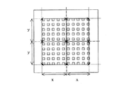
実施例1及び2のサンプル全体の反りはなく、比較例1及び2と同等で、厚肉部外表面の最も高い部分と最も低い部分の高低差により定義される成形体の反り量は15μm以下の良好な状態であった。また、図10に示す各サンプルの平面方向の寸法の測定も行い、その結果を表3に示した。実施例1及び2のサンプルの平面方向の寸法精度は全く損なわれることなく、従来方法で作製された比較例1及び2と同等の高精度なサンプルが得られた。 There is no warpage of the entire sample of Examples 1 and 2, which is equivalent to Comparative Examples 1 and 2, and the amount of warpage of the molded body defined by the difference in height between the highest part and the lowest part of the outer surface of the thick part is 15 μm or less It was in a good state. Moreover, the dimension of the planar direction of each sample shown in FIG. 10 was also measured, and the result is shown in Table 3. The dimensional accuracy in the planar direction of the samples of Examples 1 and 2 was not impaired at all, and a highly accurate sample equivalent to Comparative Examples 1 and 2 produced by the conventional method was obtained.
更に実施例1及び2のサンプルは、焼成後の再加熱が不要となったため、機械的に優れたサンプルが得られた。勿論、コスト、及び時間の削減になった。 Furthermore, since the samples of Examples 1 and 2 did not require reheating after firing, mechanically excellent samples were obtained. Of course, the cost and time were reduced.
以上説明してきたように、本発明の製造方法は、圧電/電歪膜型素子等に適用されるダイヤフラム構造を有するセラミックス体の製造に好適に適用することができる。また、本発明の治具は、このようなセラミックス体の製造に好適に使用することができる。 As described above, the production method of the present invention can be suitably applied to the production of a ceramic body having a diaphragm structure applied to a piezoelectric / electrostrictive film type element or the like. Moreover, the jig of the present invention can be suitably used for manufacturing such a ceramic body.
1…厚肉部、2(2a、2b、2c、2d)…薄肉部、3…成形体、4(4a、4b)…熱緩衝部材、6…凹部、7…連通孔、8…空所、10…セラミックス体、11…積層体、15、16…グリーンシート、17…細隙、18…貫通孔、21…スペーサー、22…加重調節部材、23…空隙、25…焼成用治具。
DESCRIPTION OF
Claims (20)
該成形体の該薄肉部と接触又は非接触の状態で該薄肉部を覆う位置に熱緩衝部材を配置して焼成を開始することを含むセラミックス体の製造方法。 A molding having a diaphragm structure in which a thick part and a thin part are provided, and the thick part and the thin part are arranged so that a recess or a void is formed by the thin part and the thick part. A method for producing a ceramic body including a step of firing a body,
A method for producing a ceramic body, comprising disposing a heat buffer member at a position covering the thin portion in a state of contact or non-contact with the thin portion of the molded body and starting firing.
0≦((Cb−Cs)/Cs)×100≦300
である請求項1〜4の何れか一項に記載のセラミックス体の製造方法。 The relationship between the heat capacity difference (C s ) per unit area between the thin part and the thick part and the heat capacity per unit area (C b ) of the heat buffer member is
0 ≦ ((C b −C s ) / C s ) × 100 ≦ 300
The method for producing a ceramic body according to any one of claims 1 to 4.
Priority Applications (2)
| Application Number | Priority Date | Filing Date | Title |
|---|---|---|---|
| JP2004376473A JP2005225748A (en) | 2004-01-13 | 2004-12-27 | Method for producing ceramic body and firing tool |
| US11/031,954 US20050206050A1 (en) | 2004-01-13 | 2005-01-07 | Method of manufacturing ceramic body and firing jig |
Applications Claiming Priority (2)
| Application Number | Priority Date | Filing Date | Title |
|---|---|---|---|
| JP2004005592 | 2004-01-13 | ||
| JP2004376473A JP2005225748A (en) | 2004-01-13 | 2004-12-27 | Method for producing ceramic body and firing tool |
Publications (1)
| Publication Number | Publication Date |
|---|---|
| JP2005225748A true JP2005225748A (en) | 2005-08-25 |
Family
ID=34985405
Family Applications (1)
| Application Number | Title | Priority Date | Filing Date |
|---|---|---|---|
| JP2004376473A Withdrawn JP2005225748A (en) | 2004-01-13 | 2004-12-27 | Method for producing ceramic body and firing tool |
Country Status (2)
| Country | Link |
|---|---|
| US (1) | US20050206050A1 (en) |
| JP (1) | JP2005225748A (en) |
Cited By (1)
| Publication number | Priority date | Publication date | Assignee | Title |
|---|---|---|---|---|
| JP2011122743A (en) * | 2009-12-08 | 2011-06-23 | Murata Mfg Co Ltd | Sheath for burning |
Families Citing this family (4)
| Publication number | Priority date | Publication date | Assignee | Title |
|---|---|---|---|---|
| JP2004263888A (en) * | 2003-02-17 | 2004-09-24 | Mitsui Mining & Smelting Co Ltd | Firing setter |
| US9240544B2 (en) | 2010-05-26 | 2016-01-19 | Ngk Insulators, Ltd. | Method of manufacturing piezoelectric element |
| EP2847143B1 (en) * | 2012-05-11 | 2020-08-12 | Keranor AS | Method for the fabrication of green ceramic tapes |
| KR102752202B1 (en) * | 2019-09-20 | 2025-01-14 | 오씨아이 주식회사 | Method for manufacturing silicon nitride substrate |
-
2004
- 2004-12-27 JP JP2004376473A patent/JP2005225748A/en not_active Withdrawn
-
2005
- 2005-01-07 US US11/031,954 patent/US20050206050A1/en not_active Abandoned
Cited By (1)
| Publication number | Priority date | Publication date | Assignee | Title |
|---|---|---|---|---|
| JP2011122743A (en) * | 2009-12-08 | 2011-06-23 | Murata Mfg Co Ltd | Sheath for burning |
Also Published As
| Publication number | Publication date |
|---|---|
| US20050206050A1 (en) | 2005-09-22 |
Similar Documents
| Publication | Publication Date | Title |
|---|---|---|
| CN113916002A (en) | Sheet ceramic pressing and sintering device and using method thereof | |
| JP2005225748A (en) | Method for producing ceramic body and firing tool | |
| JP4460325B2 (en) | Astronomical telescope mirror | |
| KR102407421B1 (en) | firing jig | |
| JP2008050222A (en) | Ceramic thin plate member | |
| JP2830796B2 (en) | Large ceramic sheet for fuel cell solid electrolyte membrane | |
| JP4421910B2 (en) | Heat treatment tray and method for producing ceramic product using the same | |
| JP2014529526A (en) | Improved method of making a ceramic body | |
| US6348115B1 (en) | Method for producing a ceramic diaphragm structure | |
| JP4445429B2 (en) | Manufacturing method of ceramic substrate | |
| JP4358777B2 (en) | Zirconia setter and method for manufacturing ceramic substrate | |
| JP6679560B2 (en) | Firing setter | |
| JPH07240217A (en) | Electrolyte substrate and flat cell manufacturing method | |
| JP4432341B2 (en) | Ceramic plate firing method | |
| JP4012871B2 (en) | Ceramic plate firing method | |
| JP2013140695A (en) | Method for manufacturing zirconia-based electrolytic sheet for fuel battery | |
| JPH059393B2 (en) | ||
| JP2007001860A (en) | Porous ceramic thin plate and method of manufacturing ceramic sheet using thin plate | |
| JPS63295480A (en) | Production of ceramic sheet | |
| JP2001114577A (en) | Porous ceramic thin plate and method for producing ceramic sheet using the thin plate | |
| JP4161618B2 (en) | Method for producing multilayer ceramic fired body | |
| JPH11228237A (en) | Firing setter | |
| JP2013075798A (en) | Method for producing ceramic sheet | |
| JPH1095664A (en) | Stock powder for ceramic sheet | |
| JP5742293B2 (en) | SETTER AND METHOD FOR MANUFACTURING CERAMIC ELECTRONIC COMPONENT |
Legal Events
| Date | Code | Title | Description |
|---|---|---|---|
| A300 | Application deemed to be withdrawn because no request for examination was validly filed |
Free format text: JAPANESE INTERMEDIATE CODE: A300 Effective date: 20080304 |