JP2005287642A - Electric kettle with tea function - Google Patents

Electric kettle with tea function Download PDF

Info

Publication number
JP2005287642A
JP2005287642A JP2004104497A JP2004104497A JP2005287642A JP 2005287642 A JP2005287642 A JP 2005287642A JP 2004104497 A JP2004104497 A JP 2004104497A JP 2004104497 A JP2004104497 A JP 2004104497A JP 2005287642 A JP2005287642 A JP 2005287642A
Authority
JP
Japan
Prior art keywords
tea
motor
tea supply
supply
hot water
Prior art date
Legal status (The legal status is an assumption and is not a legal conclusion. Google has not performed a legal analysis and makes no representation as to the accuracy of the status listed.)
Pending
Application number
JP2004104497A
Other languages
Japanese (ja)
Inventor
Shoji Miyamae
昇治 宮前
Yoshihito Tsujinaga
義仁 辻永
Kohei Imai
高平 今井
Manabu Endo
学 遠藤
Current Assignee (The listed assignees may be inaccurate. Google has not performed a legal analysis and makes no representation or warranty as to the accuracy of the list.)
Tiger Vacuum Bottle Co Ltd
Original Assignee
Tiger Vacuum Bottle Co Ltd
Priority date (The priority date is an assumption and is not a legal conclusion. Google has not performed a legal analysis and makes no representation as to the accuracy of the date listed.)
Filing date
Publication date
Application filed by Tiger Vacuum Bottle Co Ltd filed Critical Tiger Vacuum Bottle Co Ltd
Priority to JP2004104497A priority Critical patent/JP2005287642A/en
Publication of JP2005287642A publication Critical patent/JP2005287642A/en
Pending legal-status Critical Current

Links

Images

Landscapes

  • Cookers (AREA)
  • Apparatus For Making Beverages (AREA)

Abstract

【課題】 給湯機能と給茶機能との整合性、および使い勝手の良さを保ちながら、給茶モータの制御をできるだけ簡単な構成で、安価に実現することが可能な給茶機能付き電気ポットを提供する。
【解決手段】 電気ポット本体2と給茶機本体3とが一体的に結合されるとともに、両者2,3の動作を制御する制御手段12を備え、電気ポット本体2には内容器6の湯を出湯するための給湯ポンプ9が設けられる一方、給茶機本体3には給茶キー24のキー操作に応じて粉茶を茶吐出口28aまで搬送するスクリュ30、このスクリュ30を駆動する給茶モータ33が設けられており、制御手段12は、給湯ポンプ9と給茶モータ33のいずれか一方を駆動する場合には他方の動作を停止させるように構成されている。
【選択図】 図9
PROBLEM TO BE SOLVED: To provide an electric pot with a tea supply function that can be realized at a low cost with a simple configuration as much as possible while maintaining consistency between a hot water supply function and a tea supply function and ease of use. To do.
An electric pot main body 2 and a tea machine main body 3 are integrally coupled, and control means 12 for controlling operations of both the electric pot main body 2 and the electric tea pot main body 3 is provided. A hot water supply pump 9 for discharging the hot water is provided, while a tea machine main body 3 is provided with a screw 30 for conveying powdered tea to the tea discharge port 28a in response to a key operation of the tea supply key 24, and a supply for driving the screw 30 A tea motor 33 is provided, and the control means 12 is configured to stop the operation of the other when the hot water supply pump 9 or the tea supply motor 33 is driven.
[Selection] Figure 9

Description

本発明は、電気ポットに給茶機能を付属させた給茶機能付き電気ポットに関する。   The present invention relates to an electric pot with a tea supply function in which a tea supply function is attached to the electric pot.

従来より各家庭やオフィスにおいて電気ポットが広く利用されている(例えば、特許文献1参照)。また、近年では、茶葉を粉状にし、この粉茶をコップ等の容器に入れてそのまま湯を注いで喫茶することも行われている。このような粉茶は、スプーンなどで特に計量しなくても常に一定量を簡単に容器に入れることがてきれば便利である。このため、従来技術では、一定量の粉茶を供給することが可能な給茶機が提供されている。   Conventionally, electric pots have been widely used in homes and offices (see, for example, Patent Document 1). In recent years, tea leaves are made into powder, and the powdered tea is put in a container such as a cup, and hot water is poured as it is to make a tea. It is convenient if such a powdered tea can be easily put into a container at any time without being particularly measured with a spoon or the like. For this reason, in the prior art, a tea dispenser capable of supplying a certain amount of powdered tea is provided.

すなわち、従来の給茶機は、粉茶を入れるホッパの下部にスクリュを設け、このスクリュにモータを接続し、給茶スイッチを押すとモータが一定時間にわたってスクリュを回転し、これによりホッパに貯められている粉茶の一定量が給茶口から排出されるようにしている。   In other words, a conventional tea machine is provided with a screw at the bottom of a hopper for putting powdered tea, a motor is connected to this screw, and when the tea switch is pressed, the motor rotates the screw for a certain period of time, thereby storing it in the hopper. A certain amount of powdered tea is discharged from the tea outlet.

さらに、従来技術では、給茶機に対して給湯機構を接続して、粉茶と湯とを自動的にコップ等の容器に注入できるようにした装置も提供されている(例えば、特許文献2参照)。   Furthermore, in the prior art, an apparatus is also provided in which a hot water supply mechanism is connected to a tea dispenser so that powdered tea and hot water can be automatically injected into a container such as a cup (for example, Patent Document 2). reference).

特開2003−210330号公報JP 2003-210330 A 特開2000−14553号公報JP 2000-14553 A

しかしながら、前者のような給茶機単体のものは、喫茶のためには電気ポットを別途準備する必要があるので、両者を揃えることを前提として見た場合には装置全体が高価なものになる。また、電気ポットと給茶機とを別々に設置する必要があるので、設置面積を十分にとれない狭いところでは置き場所に困り、使い勝手が悪い。   However, in the case of the tea machine alone such as the former, it is necessary to prepare an electric pot separately for the coffee shop, so the whole apparatus becomes expensive when viewed on the assumption that both are arranged. . In addition, since it is necessary to install the electric kettle and the tea machine separately, it is difficult to place in a narrow place where the installation area is not sufficient and the usability is poor.

また、後者の特許文献2のものは、容器を置いておくだけで一定量の粉茶と適温の湯とが自動的に注がれるので、容器の移動が不要であり、また湯の温度も適切に設定されている分、使い勝手は良いが、従来のものは装置全体の形状が極めて大きく、家庭やオフィスの片隅に置いて利用するといったことが難しい。   In the latter case of Patent Document 2, since a certain amount of powdered tea and appropriate temperature hot water are automatically poured just by placing a container, there is no need to move the container, and the temperature of the hot water is also low. As long as it is set appropriately, it is easy to use, but the conventional device has a very large overall shape, and it is difficult to use it in a corner of a home or office.

さらに、電気ポットと給茶機とを単純に組み合わせて一つの装置にするだけでは、両者間の制御動作の整合性をとることが難しく、例えば、電気ポット側における給湯ポンプと、給茶機側において粉茶を搬出するスクリュを駆動する給茶モータとが同時に動作したときには、装置全体に対する電流負荷が大きくなり、制御基板が故障する原因になるなどの不具合を生じる。   Furthermore, it is difficult to achieve consistency in the control operation between the electric pot and the tea machine by simply combining the electric pot and the tea machine, for example, the hot water supply pump on the electric pot side and the tea machine side When the tea supply motor that drives the screw for carrying out the powdered tea is operated at the same time, the current load on the entire apparatus becomes large, causing problems such as causing the control board to fail.

本発明は、上記の問題点に鑑みてなされたもので、給湯機能と給茶機能との整合性を保ちながら適切な給茶動作を行うことができて使い勝手が良く、しかも、できるだけ簡単な構成でかつ安価に実現することが可能な給茶機能付き電気ポットを提供することを目的とする。   The present invention has been made in view of the above-described problems, and is capable of performing an appropriate tea supply operation while maintaining consistency between the hot water supply function and the tea supply function, and is easy to use and has the simplest possible configuration. An object of the present invention is to provide an electric pot with a tea supply function that can be realized at low cost.

上記の目的を達成するために、本発明の給茶機能付き電気ポットは、次の構成を採用している。   In order to achieve the above object, the electric pot with a tea supply function of the present invention employs the following configuration.

すなわち、請求項1記載における給茶機能付き電気ポットは、電気ポット本体と給茶機本体とが一体的に結合され、前記電気ポット本体には湯を貯める内容器、湯の加熱保温用のヒータ、および前記内容器の湯を出湯するための給湯ポンプが設けられる一方、前記給茶機本体には給茶操作用の給茶キー、茶を貯めるホッパ、このホッパ内の茶を茶吐出口まで搬送するスクリュ、このスクリュを駆動する給茶モータ、および前記茶吐出口を開閉する吐出口開閉手段がそれぞれ設けられ、また、前記電気ポット本体と給茶機本体の双方の動作を制御する制御手段を備え、この制御手段は、前記給湯ポンプと給茶モータのいずれか一方を駆動する場合には他方の動作を停止させるように構成されていることを特徴とする。   That is, in the electric pot with a tea supply function according to claim 1, the electric pot main body and the tea machine main body are integrally coupled, and the electric pot main body has an inner container for storing hot water, and a heater for heating and keeping hot water. And a hot water supply pump for discharging hot water in the inner container, a tea supply key for tea supply operation, a hopper for storing tea, and the tea in the hopper to the tea discharge port Control means for controlling the operations of both the electric pot body and the tea machine body, each of which includes a screw to be conveyed, a tea supply motor for driving the screw, and a discharge port opening / closing means for opening and closing the tea discharge port. The control means is configured to stop the operation of the other when the hot water supply pump or the tea supply motor is driven.

請求項2記載における給茶機能付き電気ポットは、請求項1記載の発明の構成において、前記給茶モータの負荷を検出するモータ負荷検出手段を備え、前記制御手段は、このモータ負荷検出手段の検出出力に基づいて給茶モータの負荷の有無を判断し、給茶モータが過負荷状態にあると判断した場合には給茶モータを所定時間にわたって逆転させる制御を行うものであることを特徴とする。   According to a second aspect of the present invention, there is provided an electric pot with a tea supply function according to the first aspect of the present invention, further comprising motor load detection means for detecting a load of the tea supply motor, wherein the control means is a motor load detection means. Based on the detection output, the presence or absence of a load on the tea supply motor is determined, and when it is determined that the tea supply motor is in an overload state, control is performed to reverse the tea supply motor for a predetermined time. To do.

請求項3記載における給茶機能付き電気ポットは、請求項1または請求項2に記載の発明の構成において、前記制御手段は、前記給茶キーの操作に応じて前記茶吐出口を閉じた状態のままで所定時間にわたって給茶モータを駆動した後に前記吐出口開閉手段を駆動して茶吐出口を開くシーケンス制御を行うものであることを特徴とする。   An electric pot with a tea supply function according to claim 3 is the configuration of the invention according to claim 1 or claim 2, wherein the control means closes the tea discharge port in response to an operation of the tea supply key. Then, after the tea supply motor is driven for a predetermined time, the discharge port opening / closing means is driven to perform sequence control for opening the tea discharge port.

請求項4記載における給茶機能付き電気ポットは 請求項1ないし請求項3のいずれか1項に記載の発明の構成において、前記制御手段は、前記吐出口開閉手段を駆動して茶吐出口を開いてから前記給茶モータを所定時間駆動した後に給茶モータを所定時間にわたって逆転させるシーケンス制御を行うものであることを特徴とする。   The electric pot with a tea supply function according to claim 4 is the configuration of the invention according to any one of claims 1 to 3, wherein the control means drives the discharge opening / closing means to open the tea discharge opening. A sequence control is performed in which the tea supply motor is driven for a predetermined time after opening and then the tea supply motor is reversely rotated for a predetermined time.

請求項5記載における給茶機能付き電気ポットは、請求項1ないし請求項4のいずれか1項に記載の発明の構成において、前記ホッパの着脱を検知する着脱検知手段を備え、前記制御手段は、この着脱検知手段によりホッパが装着されたことが検知された場合には前記吐出口開閉手段により茶吐出口を閉じた状態で所定時間にわたって前記給茶モータを駆動する制御を行うものであることを特徴とする。   An electric pot with a tea supply function according to claim 5 is the configuration of the invention according to any one of claims 1 to 4, further comprising an attachment / detachment detection means for detecting attachment / detachment of the hopper, wherein the control means is When the attachment / detachment detection means detects that the hopper is mounted, the tea supply motor is controlled to be driven for a predetermined time with the tea discharge opening being closed by the discharge opening / closing means. It is characterized by.

請求項6記載における給茶機能付き電気ポットは、請求項1ないし請求項5のいずれか1項に記載の発明の構成において、前記制御手段は、給茶動作の終了後に吐出口開閉手段により茶吐出口を閉じた状態で所定時間にわたって前記給茶モータを駆動して、前記モータ負荷検出手段により給茶モータの負荷を検出し、このモータ負荷検出手段で検出される給茶モータの負荷が予め設定されている基準値以下の場合には前記ホッパ内が空状態にあると判断するものであることを特徴とする。   According to a sixth aspect of the present invention, there is provided an electric pot with a tea supply function according to any one of the first to fifth aspects of the invention, wherein the control means uses the discharge port opening / closing means after the tea supply operation is completed. The tea supply motor is driven for a predetermined time with the discharge port closed, the load of the tea supply motor is detected by the motor load detection means, and the load of the tea supply motor detected by the motor load detection means is determined in advance. When the reference value is less than or equal to the set reference value, it is determined that the hopper is in an empty state.

請求項1記載の発明によれば、電気ポット本体と給茶機本体とが一体的に結合されていて、お茶を飲むために給茶モータを駆動するときには給湯ポンプが停止され、これとは逆に給湯ポンプを駆動するときには給茶モータが停止される。このように、制御手段は給湯ポンプと給茶モータとが同時に動作しないように互いを関連付けて制御するので、装置全体に対する電流容量を小さく設定できる。このため、制御基板の故障を防止でき、制御基板に使用する回路素子も小さい電流容量のものを使用できるためコストダウンを図ることができる。しかも、給茶動作と給湯動作の制御は単一の制御手段によって行われるため、装置全体の制御機能の構成が簡素化されるとともに、安価に実現することが可能になる。   According to the first aspect of the present invention, the electric pot main body and the tea machine main body are integrally coupled, and when the tea supply motor is driven to drink tea, the hot water supply pump is stopped, and vice versa. When the hot water supply pump is driven, the tea supply motor is stopped. In this way, the control means associates and controls the hot water supply pump and the tea supply motor so that they do not operate simultaneously, so the current capacity for the entire apparatus can be set small. For this reason, the failure of the control board can be prevented, and the circuit element used for the control board can be used with a small current capacity, so that the cost can be reduced. Moreover, since the tea supply operation and the hot water supply operation are controlled by a single control means, the configuration of the control function of the entire apparatus is simplified and can be realized at low cost.

請求項2記載の発明によれば、請求項1記載の発明の効果に加えて、制御手段は、モータ負荷検出手段の検出出力に基づいて、給茶モータが過負荷状態にあると判断した場合には給茶モータを所定時間にわたって逆転させるので、ホッパ内のお茶が詰まったり異物が噛み込んだりした場合に給茶モータに過負荷が加わって当該モータが故障するなどの不具合発生を防止することができる。   According to the invention described in claim 2, in addition to the effect of the invention described in claim 1, the control means determines that the tea supply motor is in an overload state based on the detection output of the motor load detection means. In this case, the tea supply motor is reversed for a predetermined period of time, so that when the tea in the hopper is clogged or a foreign object is caught, an overload is applied to the tea supply motor to prevent the motor from malfunctioning. Can do.

請求項3記載の発明によれば、請求項1または請求項2に記載の発明の効果に加えて、給茶キーの操作に応じて茶吐出口を閉じた状態のままで所定時間にわたって給茶モータを駆動した後に茶吐出口を開くので、スクリュによってお茶が茶吐出口側に向けて押しやられて詰まり、スクリュ内にお茶の無い空間が生じるのを防止できる。このため、茶吐出口を開いた後は、お茶を安定して排出することができ、常に一定濃度のお茶を飲むことができる。   According to the invention described in claim 3, in addition to the effect of the invention described in claim 1 or 2, the tea supply is performed for a predetermined time while the tea discharge port is closed according to the operation of the tea supply key. Since the tea discharge opening is opened after the motor is driven, it is possible to prevent the tea from being pushed and clogged by the screw toward the tea discharge opening, and a space without tea in the screw can be prevented. For this reason, after opening the tea outlet, tea can be discharged stably, and a constant concentration of tea can always be drunk.

請求項4記載の発明によれば、請求項1ないし請求項3のいずれか1項に記載の発明の効果に加えて、給茶動作を終了した時点から給茶モータを所定時間にわたって逆転させるので、スクリュ内のお茶がホッパ側に引き戻される。このため、余分な量のお茶が茶吐出口から落下して給茶量が安定しないといった不具合発生を防止することができる。   According to the invention described in claim 4, in addition to the effect of the invention described in any one of claims 1 to 3, the tea supply motor is reversed for a predetermined time from the time when the tea supply operation is finished. The tea in the screw is pulled back to the hopper side. For this reason, it is possible to prevent the occurrence of an inconvenience that an excessive amount of tea falls from the tea outlet and the amount of tea supplied is not stable.

請求項5記載の発明によれば、請求項1ないし請求項4のいずれか1項に記載の発明の効果に加えて、お茶を補充したホッパを給茶器本体に装着すると、これが着脱検知手段で検知され、これに応じて制御手段は茶吐出口を閉じた状態のままで所定時間にわたって給茶モータを駆動した後に茶吐出口を開くので、スクリュによってお茶が茶吐出口側に向けて押しやられて詰まり、スクリュ内にお茶の無い空間が生じるのを防止できる。このため、お茶を補充した直後からお茶を安定して排出することができ、常に一定濃度のお茶を飲むことができる。   According to the invention described in claim 5, in addition to the effect of the invention described in any one of claims 1 to 4, when the hopper supplemented with tea is attached to the tea dispenser body, this is the attachment / detachment detecting means. In response to this, the control means opens the tea discharge port after driving the tea supply motor for a predetermined time with the tea discharge port closed, so that the tea is pushed toward the tea discharge port by the screw. This can prevent clogging and creating a tea-free space in the screw. For this reason, tea can be discharged stably immediately after replenishing tea, and a constant concentration of tea can always be drunk.

請求項6記載の発明によれば、請求項1ないし請求項5のいずれか1項に記載の発明の効果に加えて、特別なセンサ等を設けなくてもホッパ内のお茶の残量を簡単な構成でもって常に把握することができるため、適切なタイミングでお茶を補充することが可能になる。   According to the invention described in claim 6, in addition to the effect of the invention described in any one of claims 1 to 5, the remaining amount of tea in the hopper can be easily reduced without providing a special sensor or the like. Since it can always grasp with a simple configuration, it becomes possible to replenish tea at an appropriate timing.

[実施の形態1]
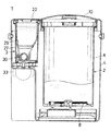
図1はこの実施の形態1における給茶機能付き電気ポットの全体を示す斜視図、図2は同正面図、図3は同平面図、図4は図2の縦断面図、図5は図2のA−A線に沿う断面図、図6は図2のB−B線に沿う断面図である。
[Embodiment 1]
1 is a perspective view showing an entire electric pot with a tea supply function in Embodiment 1, FIG. 2 is a front view thereof, FIG. 3 is a plan view thereof, FIG. 4 is a longitudinal sectional view of FIG. 2, and FIG. 2 is a cross-sectional view taken along line AA in FIG. 2, and FIG. 6 is a cross-sectional view taken along line BB in FIG.

この実施の形態1における給茶機能付き電気ポット1は、電気ポット本体2と給茶機本体3とが外装ケース4によって一体的に結合されている。   In the electric pot 1 with a tea supply function in the first embodiment, an electric pot main body 2 and a tea machine main body 3 are integrally coupled by an outer case 4.

電気ポット本体2には、湯を貯めるために断熱構造をなすステンレス鋼製の真空二重容器で構成された内容器6、湯吐出口7、内容器6の湯を加熱保温するヒータ8、内容器6の湯を湯吐出口7から出湯するための給湯ポンプ9、給水用の開閉蓋10、および湯の温度を検出する図示しない温度センサなどが設けられている。   The electric pot body 2 includes an inner container 6 composed of a stainless steel vacuum double container having a heat insulating structure for storing hot water, a hot water discharge port 7, a heater 8 for heating and keeping hot water in the inner container 6, and contents A hot water supply pump 9 for discharging the hot water of the vessel 6 from the hot water discharge port 7, an opening / closing lid 10 for supplying water, a temperature sensor (not shown) for detecting the temperature of the hot water, and the like are provided.

さらに、電気ポット本体2の開閉蓋10よりも前方側の突出部分には、給湯用操作パネル11が設けられるとともに、内部にマイクロコンピュータ(以下、単にマイコンという)で構成される制御手段12が設けられている。   Further, a hot water supply operation panel 11 is provided in a protruding portion of the electric pot body 2 on the front side of the opening / closing lid 10, and a control means 12 configured by a microcomputer (hereinafter simply referred to as a microcomputer) is provided therein. It has been.

給湯用操作パネル11には、保温モード選択キー15、湯を再沸騰させる場合に操作される再沸騰キー16、給湯ポンプ9を起動するための給湯キー17、この給湯キー17のロック状態を解除するために操作されるロック解除キー18、および液晶表示部19などが設けられている。   The hot water operation panel 11 includes a heat retention mode selection key 15, a reboiling key 16 operated when reheating the hot water, a hot water supply key 17 for starting the hot water supply pump 9, and a lock state of the hot water supply key 17 is released. An unlock key 18 that is operated to perform the operation, a liquid crystal display unit 19 and the like are provided.

そして、上記の保温モード選択キー16によって、粉茶を飲むのに適した茶対応温度(例えば、ここでは85℃)に湯を保温する茶対応保温モードを設定したり、これよりも高温(例えば、ここでは沸騰温度に近い98℃、あるいは省エネ用の90℃)に湯を保温する高温保温モードを設定できるようになっている。そして、液晶表示部19には、保温モード選択キー16で選択された保温温度(例えば85℃,98℃,90℃)や温度センサで検出される現在のお湯の温度などが表示されるようになっている。   Then, the above-described heat retention mode selection key 16 is used to set a tea correspondence heat retention mode for keeping hot water at a tea correspondence temperature (for example, 85 ° C. here) suitable for drinking powdered tea, or at a higher temperature (for example, Here, it is possible to set a high temperature heat insulation mode for keeping the hot water at 98 ° C. close to the boiling temperature or 90 ° C. for energy saving). Then, the liquid crystal display unit 19 displays the heat retention temperature (for example, 85 ° C., 98 ° C., 90 ° C.) selected by the heat retention mode selection key 16 and the current hot water temperature detected by the temperature sensor. It has become.

一方、給茶器本体3は、外装ケース4の上部に粉茶を投入したり後述のホッパ29を取り出すための開閉蓋22が設けられ、この開閉蓋22よりも前方側に給茶用操作パネル23が設けられている。そして、給茶用操作パネル23には、給茶動作を実行する場合に操作される給茶キー24や給茶状態を報知するLEDなどの表示ランプ25,26などが設けられている。   On the other hand, the tea dispenser body 3 is provided with an open / close lid 22 for pouring powdered tea into the upper part of the exterior case 4 and taking out a hopper 29 described later, and an operation panel 23 for tea supply is provided in front of the open / close lid 22. Is provided. The tea operation panel 23 is provided with tea lamp keys 24 that are operated when the tea feeding operation is performed, display lamps 25 and 26 such as LEDs for notifying the tea feeding state, and the like.

一方、外装ケース4の内部には、開閉蓋22の下方位置に内ケース27が形成されるとともに、粉茶を外部に排出する茶吐出口28aを備えた漏斗部28が形成されている。そして、内ケース27には、粉茶Pを貯留するホッパ29が着脱自在に配置され、このホッパ29の下部にはホッパ29内の粉茶を漏斗部28に送るスクリュ30が取り付けられている。また、このスクリュ30には、ギヤ31,32を介して給茶モータ33が連結されている。   On the other hand, an inner case 27 is formed inside the outer case 4 at a position below the opening / closing lid 22, and a funnel portion 28 having a tea discharge port 28a for discharging powdered tea to the outside is formed. A hopper 29 for storing powdered tea P is detachably disposed in the inner case 27, and a screw 30 for sending the powdered tea in the hopper 29 to the funnel portion 28 is attached to the lower part of the hopper 29. The tea supply motor 33 is connected to the screw 30 via gears 31 and 32.

さらに、内ケース27の下部のスクリュ27との対向位置には漏斗部28の茶吐出口28aに連通する開口部27aが形成されている。そして、この開口部27aの近傍位置にはこれを開閉するシャッタ36が揺動自在に設けられるとともに、このシャッタ36を駆動するソレノイド37が設けられている。そして、上記のシャッタ36およびソレノイド37によって特許請求の範囲における吐出口開閉手段が構成されている。   Further, an opening 27 a that communicates with the tea outlet 28 a of the funnel portion 28 is formed at a position facing the screw 27 at the lower portion of the inner case 27. A shutter 36 for opening and closing the opening 27a is provided in a swingable manner near the opening 27a, and a solenoid 37 for driving the shutter 36 is provided. The shutter 36 and the solenoid 37 constitute discharge port opening / closing means in claims.

上記の制御手段1には、マイコンに所定の制御プログラムをインストールすることにより、給湯用操作パネル11および給茶用操作パネル23の各キー15〜18,24の操作に応じて電気ポット本体2と給茶機本体3の双方の動作を制御する機能を果たすようになっている。   In the control means 1, by installing a predetermined control program in the microcomputer, the electric pot body 2 and the electric pot main body 2 can be operated according to the operation of the keys 15 to 18 and 24 of the hot water supply operation panel 11 and the tea supply operation panel 23. The function of controlling both operations of the tea machine main body 3 is achieved.

すなわち、図7に示すように、制御手段12は、給湯用操作パネル11や給茶用操作パネル23の各キー15〜18,24の操作に対応した指令信号が入力された場合、これに応じて各スイッチング素子39,40,41をオン/オフし、これよって商用の交流電源42から電源回路43を介して給湯ポンプ9、ソレノイド37、給茶モータ33に供給される各電力を制御するようになっている。   That is, as shown in FIG. 7, the control means 12 respond | corresponds to this, when the command signal corresponding to operation of each key 15-18, 24 of the hot water supply operation panel 11 or the tea operation panel 23 is input. The switching elements 39, 40, 41 are turned on / off, thereby controlling each power supplied from the commercial AC power supply 42 to the hot water supply pump 9, the solenoid 37, and the tea supply motor 33 via the power supply circuit 43. It has become.

この場合、制御手段12は、図8に示すように、電源回路43で得られる交流位相信号(ゼロクロス点検出信号)に基づいて、各スイッチング素子39〜41をオンするタイミングを選択することで給湯ポンプ9、ソレノイド37、給茶モータ33の正転/逆転方向を決定する。例えば、給茶モータ33を正転する場合には、交流位相信号がハイレベルのときにスイッチング素子41をオンにし、また、給茶モータ33を逆転する場合には、交流位相信号がローレベルのときにスイッチング素子41をオンする制御を行う。   In this case, as shown in FIG. 8, the control means 12 selects the timing for turning on each of the switching elements 39 to 41 on the basis of the AC phase signal (zero cross point detection signal) obtained by the power circuit 43. The forward / reverse direction of the pump 9, the solenoid 37, and the tea supply motor 33 is determined. For example, when the tea supply motor 33 is rotated forward, the switching element 41 is turned on when the AC phase signal is at a high level, and when the tea supply motor 33 is rotated reversely, the AC phase signal is at a low level. Sometimes the switching element 41 is turned on.

次に、上記構成の給茶機能付き電気ポット1における制御手段12による制御動作、特にここでは給湯ポンプ9と給茶モータ33の連携動作について、図9に示すフローチャートを参照して説明する。なお、以降のフローチャートにおいて、図中の符号Sは各処理ステップを意味する。   Next, the control operation by the control means 12 in the electric pot 1 with the tea supply function configured as described above, in particular, the cooperative operation of the hot water supply pump 9 and the tea supply motor 33 will be described with reference to the flowchart shown in FIG. In the following flowcharts, symbol S in the figure means each processing step.

給茶用操作パネル23の給茶キー24が操作された場合(ステップ10)、制御手段12は、先ず給湯ポンプ9をオフにした後(ステップ11)、給茶動作を開始する(ステップ12)。この給茶動作では、ソレノイド37を駆動してシャッタ36を開いた後、給茶モータ33がオンされる。これにより、ホッパ29内に貯められている粉茶Pがスクリュ30で送られて茶吐出口28aから排出され、茶吐出口28aの下方に予め置かれたコップや茶碗などの容器45内に落下される。そして、所定時間の経過後に給茶モータ33が停止された後、ソレノイド37により内ケース27の開口部27aが閉じられる。   When the tea supply key 24 of the tea supply operation panel 23 is operated (step 10), the control means 12 first turns off the hot water supply pump 9 (step 11) and then starts the tea supply operation (step 12). . In this tea supply operation, the solenoid 37 is driven to open the shutter 36, and then the tea supply motor 33 is turned on. As a result, the powdered tea P stored in the hopper 29 is sent by the screw 30 and discharged from the tea discharge port 28a, and falls into a container 45 such as a cup or teacup previously placed below the tea discharge port 28a. Is done. Then, after the tea supply motor 33 is stopped after a predetermined time has elapsed, the opening 27 a of the inner case 27 is closed by the solenoid 37.

一方、ステップ10で給茶キー24が操作されずに給湯用操作パネル11の給湯キー17が操作された場合には(ステップ13)、制御手段12は、給茶モータ33およびソレノイド37を共にオフにした後(ステップ14)、給湯動作を開始する(ステップ15)。この給湯動作では、給湯キー17が押されている間は給湯ポンプ9がオンされて内容器6の湯が湯吐出口7から容器45に出湯される。   On the other hand, when the hot water supply key 17 of the hot water supply operation panel 11 is operated without operating the tea supply key 24 in step 10 (step 13), the control means 12 turns off both the tea supply motor 33 and the solenoid 37. (Step 14), the hot water supply operation is started (Step 15). In this hot water supply operation, the hot water supply pump 9 is turned on while the hot water supply key 17 is being pressed, and the hot water in the inner container 6 is discharged from the hot water discharge port 7 to the container 45.

このように、この実施の形態1では、制御手段12が給湯ポンプ9と給茶モータ33とが同時に動作しないように互いを関連付けて制御するので、装置全体に対する電流容量を小さく設定できる。このため、制御手段12が搭載される制御基板の故障を防止でき、制御基板に使用する回路素子も小さい電流容量のものを使用できるためコストダウンを図ることができる。しかも、給茶動作と給湯動作の制御は単一の制御手段12によって行われるため、装置全体の制御機能の構成が簡素化されるとともに、安価に実現することが可能になる。   Thus, in this Embodiment 1, since the control means 12 associates and controls so that the hot water supply pump 9 and the tea supply motor 33 do not operate simultaneously, the current capacity with respect to the whole apparatus can be set small. For this reason, the failure of the control board on which the control means 12 is mounted can be prevented, and the circuit elements used for the control board can be used with a small current capacity, so that the cost can be reduced. Moreover, since the tea supply operation and the hot water supply operation are controlled by the single control means 12, the configuration of the control function of the entire apparatus is simplified and can be realized at low cost.

[実施の形態2]
この実施の形態2の給茶機能付き電気ポットの基本的な構成は、図1ないし図8に示した実施の形態1の場合と同じであるので、ここでは詳しい説明は省略する。ただし、この実施の形態2では、ホッパ29内に粉茶Pが詰まったり異物が噛み込んで給茶モータ33が故障するなどの不具合を防止するために、給茶モータ33の負荷を検出するモータ負荷検出手段として図示しないエンコーダを設けている。そして、制御手段12は、このエンコーダの検出出力に基づいて給茶モータ33の制御を次のように実行する。
[Embodiment 2]
Since the basic configuration of the electric pot with the tea supply function of the second embodiment is the same as that of the first embodiment shown in FIGS. 1 to 8, detailed description thereof is omitted here. However, in the second embodiment, a motor that detects the load of the tea supply motor 33 in order to prevent problems such as the powdered tea P being clogged in the hopper 29 or foreign matter biting in and causing the tea supply motor 33 to fail. An encoder (not shown) is provided as load detecting means. And the control means 12 performs control of the tea supply motor 33 as follows based on the detection output of this encoder.

図10はこの実施の形態2における制御手段12による給茶モータ33の制御動作の具体例を示すフローチャートである。なお、ここでは説明の都合上、ソレノイド37の動作は省略しているが、給茶動作には当然ながらソレノイド37によるシャッタ36の開閉動作を伴うものである。また、以下の説明における内部タイマは、制御手段12によるプログラムによって実現されるものである。   FIG. 10 is a flowchart showing a specific example of the control operation of the tea supply motor 33 by the control means 12 in the second embodiment. Here, for convenience of explanation, the operation of the solenoid 37 is omitted, but the tea supply operation naturally involves the opening and closing operation of the shutter 36 by the solenoid 37. Further, the internal timer in the following description is realized by a program by the control means 12.

給茶キー24がオンされると(ステップ20)、制御手段12は、給茶モータ33を正転させる(ステップ21)。次いで、制御手段12はエンコーダの出力が有るかいなかを判断する(ステップ22)。エンコーダの出力があるときには、ホッパ29内に粉茶の詰まりや異物の噛み込みは無いものと判断して処理を終了する。   When the tea supply key 24 is turned on (step 20), the control means 12 causes the tea supply motor 33 to rotate forward (step 21). Next, the control means 12 determines whether there is an output from the encoder (step 22). When there is an output from the encoder, it is determined that there is no powder tea jam or foreign matter biting in the hopper 29 and the process is terminated.

これに対して、エンコーダの出力がないときには、ホッパ29内に粉茶の詰まりや異物の噛み込みがあるものと判断し、次に制御手段12は内部に備える第1内部タイマをセットする(ステップ23)。そして、所定時間(T1、例えばT1=1秒)が経過して第1内部タイマがタイムアップするまで給茶モータ33を逆転させる(ステップ24,25)。   On the other hand, when there is no output from the encoder, it is determined that there is a clogging of powdered tea or a foreign object in the hopper 29, and then the control means 12 sets a first internal timer provided inside (step). 23). Then, the tea supply motor 33 is reversely rotated until a predetermined time (T1, for example, T1 = 1 second) elapses and the first internal timer expires (steps 24 and 25).

第1内部タイマがタイムアップすると、次に、制御手段12は第2内部タイマをセットする(ステップ26)。そして、所定時間(T2、例えばT2=1秒)が経過して第2内部タイマがタイムアップするまで給茶モータ33を正転させる(ステップ27,28)。第2内部タイマがタイムアップすると、制御手段12は、逆転および正転の繰り返し回数をカウントするカウンタのカウント値Nを一つ繰り上げた後(ステップ29)、そのカウント値Nが予め設定した閾値Nsh(例えばNsh=2)を越えたか否かを判断する(ステップ30)。カウント値Nが閾値Nshを越えていなければ、ステップ22に戻り、再びエンコーダの出力があるか否かを判断する。   When the first internal timer expires, the control means 12 then sets the second internal timer (step 26). Then, the tea supply motor 33 is rotated forward until a predetermined time (T2, for example, T2 = 1 second) elapses and the second internal timer expires (steps 27 and 28). When the second internal timer expires, the control means 12 increments the count value N of the counter that counts the number of repetitions of reverse rotation and forward rotation by one (step 29), and then the count value N is set to a preset threshold value Nsh. It is determined whether or not (for example, Nsh = 2) has been exceeded (step 30). If the count value N does not exceed the threshold value Nsh, the process returns to step 22 to determine again whether there is an encoder output.

このとき、エンコーダの出力が得られた場合には、ホッパ29内の粉茶の詰まりや異物の噛み込みが解消したもと判断して処理を終了する。これに対して、エンコーダの出力が得られない場合には、依然としてホッパ29内に粉茶の詰まりや異物の噛み込みが生じているものと判断し、ステップ22〜ステップ30を繰り返す。   At this time, when the output of the encoder is obtained, it is determined that the clogging of powdered tea in the hopper 29 or the biting of foreign matter has been resolved, and the process is terminated. On the other hand, when the output of the encoder cannot be obtained, it is determined that the powdered tea is still clogged or the foreign matter is stuck in the hopper 29, and Steps 22 to 30 are repeated.

こうしてステップ22〜ステップ30を所定回数繰り返してもホッパ29内の粉茶の詰まりや異物の噛み込みが解消せず、カウント値がカウトアップしたときは(ステップ30)、制御手段12は、給茶用操作パネル23に設けられている警告用の表示ランプ26を点滅するなどしてエラー表示を行う(ステップ31)。   Thus, even if the steps 22 to 30 are repeated a predetermined number of times, if the powdered tea clogging or foreign matter biting in the hopper 29 is not eliminated and the count value is counted up (step 30), the control means 12 is used for tea supply. An error is displayed by blinking a warning display lamp 26 provided on the operation panel 23 (step 31).

このように、この実施の形態2では、ホッパ29内に粉茶が詰まったり異物が噛み込んだりして給茶モータ33が過負荷状態になるような場合には、その原因を解消するように給茶モータ33が所定時間にわたって逆転されてがるので、当該モータ33が故障するなどの不具合発生を防止することができる。   As described above, in the second embodiment, when the tea supply motor 33 is overloaded due to clogged powdered tea or foreign matter in the hopper 29, the cause is eliminated. Since the tea supply motor 33 is reversely rotated for a predetermined time, it is possible to prevent the occurrence of a malfunction such as a failure of the motor 33.

なお、上記の実施の形態2では、モータ負荷検出手段としてエンコーダを設けたが、これに限らず、例えば、給茶モータ33の電流値をモニタする電流検出器をモータ負荷検出手段として設け、電流検出器で検出される給茶モータ33の電流値が予め設定された基準値以上の場合には、ホッパ29内に粉茶が詰まったり異物が噛み込んだりしたものと判断するように構成することも可能である。   In the second embodiment, the encoder is provided as the motor load detecting means. However, the present invention is not limited to this. For example, a current detector that monitors the current value of the tea supply motor 33 is provided as the motor load detecting means. When the current value of the tea supply motor 33 detected by the detector is greater than or equal to a preset reference value, it is determined that powdered tea is clogged or foreign matter is caught in the hopper 29. Is also possible.

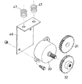
また、上記の実施の形態2では、給茶モータ33の電気的な制御によって過負荷が加わるのを防止したが、例えば、図11に示すような機械的な機構によって給茶モータ33に過負荷が加わるのを防止することも可能である。   In the second embodiment, overload is prevented from being applied by electrical control of the tea supply motor 33. For example, the overload is applied to the tea supply motor 33 by a mechanical mechanism as shown in FIG. It is also possible to prevent the addition of.

すなわち、図11では、給茶モータ33が取り付けられたブラケット46をゴム製のクッションパッキン47を介して内ケース27に取り付けてスプリング効果を備えるようにしておき、給茶モータ33に過負荷が生じた場合には、給茶モータ33とスクリュ間を連結するギヤ31,32が外れるようにしている。このようにしても、給茶モータ33に過負荷が生じるのを防止することが可能である。   That is, in FIG. 11, the bracket 46 to which the tea supply motor 33 is attached is attached to the inner case 27 via the rubber cushion packing 47 so as to have a spring effect, and the tea supply motor 33 is overloaded. In this case, the gears 31 and 32 connecting the tea supply motor 33 and the screw are disengaged. Even in this case, it is possible to prevent the tea supply motor 33 from being overloaded.

[実施の形態3]
この実施の形態3の給茶機能付き電気ポットの基本的な構成は図1ないし図8に示した実施の形態1の場合と同様であるので、ここでは詳しい説明は省略する。
[Embodiment 3]
Since the basic configuration of the electric pot with a tea supply function of the third embodiment is the same as that of the first embodiment shown in FIGS. 1 to 8, detailed description thereof is omitted here.

この実施の形態3の特徴は、制御手段12による給茶モータ33の動作制御によって粉茶Pが常に安定して排出されるようにした点にある。したがって、ここでは制御手段1によるによる給茶モータ33の制御動作について、図12に示すフローチャートを参照して説明する。   The feature of the third embodiment resides in that the powdered tea P is always discharged stably by the operation control of the tea supply motor 33 by the control means 12. Therefore, here, the control operation of the tea supply motor 33 by the control means 1 will be described with reference to the flowchart shown in FIG.

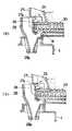
まず、給茶キー24がオンされると(ステップ40)、これに応じて制御手段は第3内部タイマをセットした後(ステップ41)、第3内部タイマがタイムアップするまでの所定期間T3(例えばT3=1秒)、給茶モータ33を駆動する(ステップ42,43)。第3内部タイマがタイムアップするまでの期間T3内はソレノイド37はオフの状態にあり、このため開口部27aはシャッタ36により閉じられている。したがって、図13に示すように、スクリュ3によって粉茶Pが開口部27a側に向けて押しやられて詰まるため、スクリュ30内に粉茶Pの無い空間Bが生じるのを防止できる。   First, when the tea supply key 24 is turned on (step 40), the control means sets the third internal timer accordingly (step 41), and then the predetermined period T3 (until the third internal timer expires). For example, T3 = 1 second), the tea supply motor 33 is driven (steps 42 and 43). During the period T3 until the third internal timer expires, the solenoid 37 is in an off state, and therefore the opening 27a is closed by the shutter 36. Accordingly, as shown in FIG. 13, the powder 3 is pushed and clogged by the screw 3 toward the opening 27 a side, so that it is possible to prevent the space 30 without the powder tea P from being generated in the screw 30.

すなわち、前回の給茶動作が終了した後、あるいは粉茶Pをホッパ29内に補給した後は、図13(a)に示すようにスクリュ30の先端部分には粉茶Pが存在しない空間Bが形成され易く、そのままシャッタ36を開いて給茶動作を開始しても、粉茶Pがスクリュ30で送られて実際に茶吐出口28aから吐出されるまでに時間がかかり、一定量の粉茶が排出されないことが起こる。これに対して、シャッタ36で開口部27aを閉じた状態のままスクリュ30を回すと、図13(b)に示すようにスクリュ30の先端部分に粉茶Pが詰まるので、シャッタ36を開けば直ちに茶吐出口28aから粉茶Pが排出されるようになる。   That is, after the previous tea supply operation is completed or after the powdered tea P is supplied into the hopper 29, as shown in FIG. 13A, the space B where the powdered tea P does not exist at the tip portion of the screw 30. Even if the shutter 36 is opened and the tea supply operation is started as it is, it takes time until the powdered tea P is fed by the screw 30 and actually discharged from the tea discharge port 28a, and a certain amount of powder is generated. It happens that tea is not discharged. On the other hand, if the screw 30 is turned with the shutter 27 closed with the opening 27a, powder tea P is clogged at the tip of the screw 30 as shown in FIG. The powdered tea P is immediately discharged from the tea discharge port 28a.

そして、所定期間T3が経過して第3内部タイマがタイムアップすると、制御手段12はソレノイド37を駆動してシャッタ36を開き(ステップ44)、次いで、第4内部タイマをセットする(ステップ45)。この場合、給茶モータ33は既に駆動されているので、引き続いて、制御手段12は、所定時間T4(例えばT4=2秒)が経過してこの第4内部タイマがタイムアップするまで給茶モータ33の駆動を継続する(ステップ46)。そして、第4内部タイマがタイムアップすると給茶モータ33を停止させる(ステップ47)。これにより、ホッパ29内の一定量の粉茶Pがスクリュ30で茶吐出口28aに送られて茶吐出口28aの下方に置いた容器45内に供給される。   When the third internal timer expires after the lapse of the predetermined period T3, the control means 12 drives the solenoid 37 to open the shutter 36 (step 44), and then sets the fourth internal timer (step 45). . In this case, since the tea supply motor 33 has already been driven, the control unit 12 continues the tea supply motor until a predetermined time T4 (for example, T4 = 2 seconds) elapses and the fourth internal timer expires. The drive of 33 is continued (step 46). When the fourth internal timer expires, the tea supply motor 33 is stopped (step 47). Thereby, a certain amount of powdered tea P in the hopper 29 is sent to the tea discharge port 28a by the screw 30 and supplied into the container 45 placed below the tea discharge port 28a.

続いて、制御手段12は、第5内部タイマをセットし(ステップ48)、所定時間T5(例えばT5=0.3秒)が経過してこの第5内部タイマがタイムアップするまでの間、給茶モータ33を逆転させた後(ステップ49,50)、給茶モータ33を停止する(ステップ51)。これにより、スクリュ30の先端部分に溜まっている粉茶Pがホッパ29側に引き戻される。このため、余分な量の粉茶Pが茶吐出口28aから落下して給茶量が安定しないといった不具合発生を防止することができる。   Subsequently, the control means 12 sets a fifth internal timer (step 48), and supplies it until a predetermined time T5 (for example, T5 = 0.3 seconds) elapses until the fifth internal timer expires. After the tea motor 33 is reversed (steps 49 and 50), the tea supply motor 33 is stopped (step 51). Thereby, the powdered tea P collected at the tip of the screw 30 is pulled back to the hopper 29 side. For this reason, it is possible to prevent the occurrence of an inconvenience that an excessive amount of powdered tea P falls from the tea discharge port 28a and the amount of tea supplied is not stable.

すなわち、図14(a)に示すように、シャッタ36を開いた状態でスクリュ30を停止させると、シャッタ36を閉じるまでの間にスクリュ30の先端部分に溜まっている粉茶Pが余分に茶吐出口28aから落下して給茶量が不安定になる恐れがある。これに対して、給茶モータ33を逆転させると、図14(b)に示すようにスクリュ30の先端部分に溜まっている粉茶Pがホッパ29側に引き戻されるため余分に落下するのを防止することができ、常に安定した給茶量を確保することができる。   That is, as shown in FIG. 14A, if the screw 30 is stopped with the shutter 36 opened, the powdered tea P accumulated at the tip of the screw 30 until the shutter 36 is closed is excessively brown. There is a possibility that the amount of tea supply will become unstable due to falling from the discharge port 28a. On the other hand, when the tea supply motor 33 is reversed, the powdered tea P collected at the tip of the screw 30 is pulled back toward the hopper 29 as shown in FIG. It is possible to ensure a stable amount of tea supply.

そして、給茶モータ33の停止後は、ソレノイド37をオフにしてシャッタ36により開口部27aを閉じ(ステップ52)、引き続いて、給茶用操作パネル23に設けられている表示ランプ25を点滅するなどして給茶動作が終了したことを報知する(ステップ53)。   After stopping the tea supply motor 33, the solenoid 37 is turned off and the opening 27a is closed by the shutter 36 (step 52). Subsequently, the display lamp 25 provided on the tea operation panel 23 blinks. For example, the fact that the tea supply operation has been completed is notified (step 53).

このように、この実施の形態3では、給茶キー24が操作されたときには、これに応じて茶吐出口28aを閉じた状態のままで所定時間にわたって給茶モータ33を駆動するので、スクリュ30によって粉茶Pが開口部27a側に向けて押しやられて詰まるので、スクリュ30内に粉茶Pの無い空間Bが生じるのを防止でき、粉茶Pを安定して排出することができる。   As described above, in the third embodiment, when the tea supply key 24 is operated, the tea supply motor 33 is driven for a predetermined time while the tea discharge port 28a is closed in accordance with this operation. Therefore, the powdered tea P is pushed and clogged toward the opening 27a side, so that it is possible to prevent the space B without the powdered tea P from being generated in the screw 30, and the powdered tea P can be discharged stably.

しかも、この実施の形態3では、給茶動作を終了した時点から給茶モータ33を所定時間にわたって逆転させるので、スクリュ30内の粉茶Pがホッパ29側に引き戻される。このため、余分な量の粉茶Pが茶吐出口28aから落下して給茶量が安定しないといった不具合発生を防止することができ、常に一定濃度のお茶を飲むことができる。   Moreover, in the third embodiment, since the tea supply motor 33 is reversed for a predetermined time from the time when the tea supply operation is finished, the powdered tea P in the screw 30 is pulled back to the hopper 29 side. For this reason, it is possible to prevent the occurrence of an inconvenience that an excessive amount of powdered tea P falls from the tea discharge port 28a and the amount of tea supplied is not stable, and a constant concentration of tea can be always drunk.

[実施の形態4]
この実施の形態4の給茶機能付き電気ポットの基本的な構成は、図1ないし図8に示した実施の形態1の場合と同じであるので、ここでは詳しい説明は省略する。ただし、この実施の形態4では、粉茶Pを補給した直後から粉茶Pを安定して排出できるように、図15に示すように、ホッパ29の内ケース27への着脱の有無を検知する着脱検知手段としてのスイッチ48を設けている。すなわち、このスイッチ48は、内ケース27にホッパ29が装着されたときにオンし、内ケース27からホッパ29が取り外された場合にはオフするようになっている。そして、制御手段12は、このスイッチ48の出力に基づいて給茶モータ33の制御を次のように実行する。
[Embodiment 4]
Since the basic configuration of the electric pot with the tea supply function of the fourth embodiment is the same as that of the first embodiment shown in FIGS. 1 to 8, detailed description thereof is omitted here. However, in the fourth embodiment, as shown in FIG. 15, it is detected whether the hopper 29 is attached to or detached from the inner case 27 so that the powdered tea P can be stably discharged immediately after the powdered tea P is replenished. A switch 48 is provided as attachment / detachment detection means. That is, the switch 48 is turned on when the hopper 29 is mounted on the inner case 27 and turned off when the hopper 29 is removed from the inner case 27. And the control means 12 performs control of the tea supply motor 33 based on the output of this switch 48 as follows.

すなわち、図16のフローチャートに示すように、制御手段12は、スイッチ48の出力に基づいて内ケース27にホッパ29が装着されたか否かを判断する(ステップ60)。ホッパ29に粉茶Pが補充した後、ホッパ29を内ケース27に装着して開閉蓋22が閉じられたときには、スイッチ48がオンするので、この検出出力に基づいて制御手段12は第7内部タイマをセットした後(ステップ61)、給茶モータ33を起動する(ステップ62)。なお、その際、レノイド37はオフの状態にあって開口部27aはシャッタ36により閉じられている。   That is, as shown in the flowchart of FIG. 16, the control means 12 determines whether or not the hopper 29 is attached to the inner case 27 based on the output of the switch 48 (step 60). After the powdered tea P is replenished to the hopper 29, when the hopper 29 is mounted on the inner case 27 and the open / close lid 22 is closed, the switch 48 is turned on. Based on this detection output, the control means 12 After setting the timer (step 61), the tea supply motor 33 is started (step 62). At that time, the renoid 37 is in an off state, and the opening 27 a is closed by the shutter 36.

そして、給茶モータ33に過負荷が検知されるか否かを判断し(ステップ64)、過負荷が検知されたならば直ちに給茶モータ33を停止する(ステップ65)。これに対して、過負荷が検知されない場合には、第7内部タイマがタイムアップしたか否かを判断し(ステップ64)、タイムアップしていないとステップ62に戻って給茶モータ33の駆動を継続する。そして、所定時間T7(例えばT7=3秒)が経過して第7内部タイマがタイムアップすると給茶モータ33を停止する(ステップ65)。   Then, it is determined whether or not an overload is detected in the tea supply motor 33 (step 64). If an overload is detected, the tea supply motor 33 is immediately stopped (step 65). On the other hand, if no overload is detected, it is determined whether or not the seventh internal timer has timed up (step 64). If the time has not expired, the process returns to step 62 to drive the tea supply motor 33. Continue. Then, when a predetermined time T7 (for example, T7 = 3 seconds) elapses and the seventh internal timer expires, the tea supply motor 33 is stopped (step 65).

このように、この実施の形態4では、粉茶Pを補充したホッパ29が内ケース27に装着されたことが検知されると、これに応じて制御手段12は開口部27aを閉じた状態のままで所定時間T7にわたって給茶モータ33を駆動するので、スクリュ30によって粉茶Pが開口部27a側に向けて押しやられて詰まるので、スクリュ30内に粉茶の無い空間が生じるのを防止できる。このため、粉茶Pをホッパ29に補充した直後から粉茶Pを安定して排出することができ、常に一定濃度の粉茶を飲むことができる。   As described above, in the fourth embodiment, when it is detected that the hopper 29 supplemented with powdered tea P is attached to the inner case 27, the control means 12 is in a state of closing the opening 27a accordingly. Since the tea supply motor 33 is driven for a predetermined time T7 as it is, the powdered tea P is pushed and clogged by the screw 30 toward the opening 27a side, so that it is possible to prevent a space without powdered tea from forming in the screw 30. . For this reason, the powdered tea P can be stably discharged immediately after the powdered tea P is replenished to the hopper 29, and a constant concentration of powdered tea can always be drunk.

[実施の形態5]
この実施の形態5の給茶機能付き電気ポットの基本的な構成は、図1ないし図8に示した実施の形態1の場合と同じであるので、ここでは詳しい説明は省略する。ただし、この実施の形態5では、ホッパ29内の粉茶Pの残量を把握できるように、ホッパ29の上方の開閉蓋22の開閉状態を検知するスイッチ(図示せず)を設けている。そして、制御手段12は、このスイッチの出力に基づいて給茶モータ33の制御を次のように実行する。
[Embodiment 5]
Since the basic configuration of the electric pot with a tea supply function according to the fifth embodiment is the same as that of the first embodiment shown in FIGS. 1 to 8, detailed description thereof is omitted here. However, in the fifth embodiment, a switch (not shown) for detecting the open / close state of the open / close lid 22 above the hopper 29 is provided so that the remaining amount of the powdered tea P in the hopper 29 can be grasped. And the control means 12 performs control of the tea supply motor 33 as follows based on the output of this switch.

すなわち、図17のフローチャートに示すように、例えば、図10に示したような給茶動作が全て終了すると(ステップ70)、引き続いて、制御手段12は、図示しないスイッチの検出出力に基づいてホッパ29の上方の開閉蓋22が閉じられているか否かを判断する(ステップ71)。   That is, as shown in the flowchart of FIG. 17, for example, when all the tea supply operations as shown in FIG. 10 are completed (step 70), the control unit 12 continues to operate the hopper based on the detection output of the switch (not shown). It is determined whether or not the opening / closing lid 22 above 29 is closed (step 71).

開閉蓋22が閉じられているならば、次に、制御手段12は第9内部タイマをセットした後(ステップ72)、給茶モータ33を起動する(ステップ73)。なお、その際、ソレノイド37はオフの状態にあって開口部27aはシャッタ36により閉じられている。この状態で、制御手段12は、モータ負荷検出手段(例えば、茶モータ33の電流値をモニタする電流検出器)の検出出力に基づいて給茶モータ33の負荷を検出する(ステップ74)。そして、検出した給茶モータ33の負荷が予め設定されている基準値以下か否かを判断する(ステップ75)。   If the open / close lid 22 is closed, the control means 12 then sets the ninth internal timer (step 72) and then starts the tea supply motor 33 (step 73). At that time, the solenoid 37 is in an off state, and the opening 27 a is closed by the shutter 36. In this state, the control means 12 detects the load of the tea supply motor 33 based on the detection output of the motor load detection means (for example, a current detector that monitors the current value of the brown motor 33) (step 74). Then, it is determined whether or not the detected load of the tea supply motor 33 is equal to or less than a preset reference value (step 75).

このとき、給茶モータ33の負荷が予め設定されている基準値を越えている場合には、ホッパ29内には十分な粉茶Pが貯留されているものと判断し、給茶モータ33を停止する(ステップ76)。これに対して、給茶モータ33の負荷が予め設定されている基準値を越えた場合には、再度ステップ73に戻り、給茶モータ33を回転を継続し、モータ負荷を検出して給茶モータ33の負荷が予め設定されている基準値を越えているか否かを判断する(ステップ74,75)。   At this time, if the load of the tea supply motor 33 exceeds a preset reference value, it is determined that sufficient powdered tea P is stored in the hopper 29, and the tea supply motor 33 is turned on. Stop (step 76). On the other hand, when the load of the tea supply motor 33 exceeds a preset reference value, the process returns to step 73 again, the tea supply motor 33 is continuously rotated, the motor load is detected, and the tea supply is performed. It is determined whether or not the load of the motor 33 exceeds a preset reference value (steps 74 and 75).

そして、第9内部タイマでセットした所定時間T9(例えばT9=5秒)が経過しても給茶モータ33の負荷が予め設定されている基準値以下のままであるときには、ホッパ29内の粉茶Pは空になっていると判断し、給茶モータ33を停止するとともに(ステップ78)、給茶用操作パネル23に設けられている警告用の表示ランプ26を点滅するなどしてホッパ29内の粉茶Pが空になっていることを報知する(ステップ79)。   If the load on the tea supply motor 33 remains below a preset reference value even after a predetermined time T9 (for example, T9 = 5 seconds) set by the ninth internal timer has elapsed, the powder in the hopper 29 The tea P is determined to be empty, the tea supply motor 33 is stopped (step 78), and the warning display lamp 26 provided on the tea supply operation panel 23 is flashed. It is notified that the powdered tea P is empty (step 79).

このように、この実施の形態5では、特別な容量センサなどを設けなくてもホッパ29内の粉茶Pの残量を簡単な構成でもって常に把握することができるため、適切なタイミングで粉茶Pを補充することが可能になる。   As described above, in the fifth embodiment, since the remaining amount of the powdered tea P in the hopper 29 can be always grasped with a simple configuration without providing a special capacity sensor or the like, Tea P can be replenished.

上記の各実施の形態1〜5について、次のような各種の変形例や応用例を考えることができる。
上記の各実施の形態1〜5では、粉茶Pを給茶する場合について説明したが、本発明はこれに限定されるものではなく、紅茶やコーヒーなど、他の茶種を給茶する場合についても適用することができる。
About each said Embodiment 1-5, the following various modifications and application examples can be considered.
In each of the above-described first to fifth embodiments, the case of supplying powdered tea P has been described, but the present invention is not limited to this, and the case of supplying other tea types such as tea and coffee Can also be applied.

また、給茶モータ33の駆動方法として、全て同じ回転数を維持するのではなくて、起動直後は回転数が低く設定し、時間経過に伴って次第に回転数を増加させる制御を行うこともできる。このような回転数制御を行えば、給茶動作が円滑に行えるとともに、起動時の負荷軽減に役立てることができる。   Further, as a driving method of the tea supply motor 33, it is possible to set the rotation number to be low immediately after startup and control to gradually increase the rotation number as time passes, instead of maintaining the same rotation number. . By performing such rotation speed control, the tea supply operation can be performed smoothly, and it can be used to reduce the load at the time of startup.

さらにまた、上記の各実施の形態1〜5においては、単一の制御手段を設け、この制御手段によって給茶機能と給湯機能とを共に制御している。しかし、既存の電気ポットの給湯機能をそのまま維持して、給茶機能のみを新たに付加する場合には給茶機本体3側に専用の制御手段を設け、電気ポット側の制御手段との連携をとるように構成することも可能である。これにより、新たに制御プログラムを作成する場合に比較して開発費の削減が可能になる。   Furthermore, in each of the above-described first to fifth embodiments, a single control unit is provided, and both the tea supply function and the hot water supply function are controlled by this control unit. However, when the hot water supply function of the existing electric pot is maintained as it is and only the tea supply function is newly added, a dedicated control means is provided on the tea machine body 3 side, and cooperation with the control means on the electric pot side is provided. It is also possible to configure to take. As a result, the development cost can be reduced as compared with the case where a new control program is created.

本発明の実施の形態1における給茶機能付き電気ポットの全体を示す斜視図である。It is a perspective view which shows the whole electric pot with a tea supply function in Embodiment 1 of this invention. 図1の給茶機能付き電気ポットの正面図である。It is a front view of the electric pot with a tea supply function of FIG. 図1の給茶機能付き電気ポットの平面図である。It is a top view of the electric pot with a tea supply function of FIG. 図2の縦断面図である。It is a longitudinal cross-sectional view of FIG. 図2のA−A線に沿う断面図である。It is sectional drawing which follows the AA line of FIG. 図2のB−B線に沿う断面図である。It is sectional drawing which follows the BB line of FIG. 本発明の実施の形態1における給茶機能付き電気ポットにおいて、制御手段による給湯ポンプ、ソレノイド、給茶モータの各制御状態を示す回路ブロック図である。It is a circuit block diagram which shows each control state of the hot water supply pump by a control means, a solenoid, and a tea supply motor in the electric pot with a tea supply function in Embodiment 1 of this invention. 本発明の実施の形態1における給茶機能付き電気ポットにおいて、制御手段による給湯ポンプ、ソレノイド、給茶モータの各制御タイミングを示すタイミングチャートである。It is a timing chart which shows each control timing of the hot water supply pump by a control means, a solenoid, and a tea supply motor in the electric pot with a tea supply function in Embodiment 1 of this invention. 本発明の実施の形態1の給茶機能付き電気ポットにおいて、制御手段による給湯ポンプと給茶モータの制御動作の説明に供するフローチャートである。It is a flowchart with which it uses for description of control operation | movement of the hot water supply pump and tea supply motor by a control means in the electric pot with a tea supply function of Embodiment 1 of this invention. 本発明の実施の形態2の給茶機能付き電気ポットにおいて、制御手段による給茶モータの制御動作の説明に供するタイミングチャートである。It is a timing chart with which it uses for description of control operation | movement of the tea supply motor by a control means in the electric pot with a tea supply function of Embodiment 2 of this invention. 本発明の実施の形態2に関連して、給茶モータに過負荷が加わるのを防止するための他の手段を示す斜視図である。In connection with Embodiment 2 of this invention, it is a perspective view which shows the other means for preventing that an overload is added to a tea supply motor. 本発明の実施の形態3の給茶機能付き電気ポットにおいて、制御手段による給茶モータの制御動作の説明に供するフローチャートである。It is a flowchart with which it uses for description of control operation | movement of the tea supply motor by a control means in the electric pot with a tea supply function of Embodiment 3 of this invention. 図12のフローチャートに関連した給茶モータの制御動作の説明図である。It is explanatory drawing of the control operation of the tea supply motor relevant to the flowchart of FIG. 図12のフローチャートに関連した給茶モータの制御動作の説明図である。It is explanatory drawing of the control operation of the tea supply motor relevant to the flowchart of FIG. 本発明の実施の形態4の給茶機能付き電気ポットにおける要部構成を示す断面図である。It is sectional drawing which shows the principal part structure in the electric pot with a tea supply function of Embodiment 4 of this invention. 本発明の実施の形態4の給茶機能付き電気ポットにおいて、制御手段による給茶モータの制御動作の説明に供するフローチャートである。It is a flowchart with which it uses for description of control operation | movement of the tea supply motor by a control means in the electric pot with a tea supply function of Embodiment 4 of this invention. 本発明の実施の形態5の給茶機能付き電気ポットにおいて、制御手段による給茶モータの制御動作の説明に供するフローチャートである。It is a flowchart with which it uses for description of control operation | movement of the tea supply motor by a control means in the electric pot with a tea supply function of Embodiment 5 of this invention.

符号の説明Explanation of symbols

1 給茶機能付き電気ポット
2 電気ポット本体
3 給茶機本体
6 内容器
7 湯吐出口
8 ヒータ
9 給湯ポンプ
12 制御手段
17 給湯キー
24 給茶キー
28a 茶吐出口
29 ホッパ
30 スクリュ
33 給茶モータ
36 シャッタ
37 ソレノイド
48 スイッチ(着脱検知手段)
DESCRIPTION OF SYMBOLS 1 Electric pot with tea supply function 2 Electric pot body 3 Tea machine body 6 Inner container 7 Hot water discharge port 8 Heater 9 Hot water supply pump 12 Control means 17 Hot water key 24 Tea supply key 28a Tea discharge port 29 Hopper 30 Screw 33 Tea supply motor 36 Shutter 37 Solenoid 48 Switch (detachment detection means)

Claims (6)

電気ポット本体と給茶機本体とが一体的に結合され、前記電気ポット本体には湯を貯める内容器、湯の加熱保温用のヒータ、および前記内容器の湯を出湯するための給湯ポンプが設けられる一方、前記給茶機本体には給茶操作用の給茶キー、茶を貯めるホッパ、このホッパ内の茶を茶吐出口まで搬送するスクリュ、このスクリュを駆動する給茶モータ、および前記茶吐出口を開閉する吐出口開閉手段がそれぞれ設けられ、また、前記電気ポット本体と給茶機本体の双方の動作を制御する制御手段を備え、この制御手段は、前記給湯ポンプと給茶モータのいずれか一方を駆動する場合には他方の動作を停止させるように構成されていることを特徴とする給茶機能付き電気ポット。 An electric pot main body and a tea machine main body are integrally coupled, and the electric pot main body includes an inner container for storing hot water, a heater for heating and keeping hot water, and a hot water supply pump for discharging the hot water in the inner container. On the other hand, the tea machine body has a tea supply key for tea supply operation, a hopper for storing tea, a screw for transporting tea in the hopper to a tea discharge port, a tea supply motor for driving the screw, Discharge port opening / closing means for opening and closing the tea discharge port are provided, respectively, and control means for controlling the operation of both the electric pot main body and the tea machine main body is provided. The control means includes the hot water supply pump and the tea supply motor. An electric pot with a tea supply function is configured to stop the operation of the other when either one is driven. 前記給茶モータの負荷を検出するモータ負荷検出手段を備え、前記制御手段は、このモータ負荷検出手段の検出出力に基づいて給茶モータの負荷の有無を判断し、給茶モータが過負荷状態にあると判断した場合には給茶モータを所定時間にわたって逆転させる制御を行うものであることを特徴とする請求項1記載の給茶機能付き電気ポット。 Motor load detection means for detecting the load of the tea supply motor is provided, and the control means determines the presence or absence of the load of the tea supply motor based on the detection output of the motor load detection means, and the tea supply motor is overloaded. The electric pot with a tea supply function according to claim 1, wherein when it is determined that the tea supply motor is in reverse, control is performed to reverse the tea supply motor for a predetermined time. 前記制御手段は、前記給茶キーの操作に応じて前記茶吐出口を閉じた状態のままで所定時間にわたって給茶モータを駆動した後に前記吐出口開閉手段を駆動して茶吐出口を開くシーケンス制御を行うものであることを特徴とする請求項1または請求項2に記載の給茶機能付き電気ポット。 A sequence in which the control means opens the tea discharge port by driving the discharge port opening / closing means after driving the tea supply motor for a predetermined time while the tea discharge port is closed in accordance with the operation of the tea supply key. The electric pot with a tea supply function according to claim 1 or 2, wherein the electric pot is controlled. 前記制御手段は、前記吐出口開閉手段を駆動して茶吐出口を開いてから前記給茶モータを所定時間駆動した後に給茶モータを所定時間にわたって逆転させるシーケンス制御を行うものであることを特徴とする請求項1ないし請求項3のいずれか1項に記載の給茶機能付き電気ポット。 The control means performs sequence control for driving the tea supply motor for a predetermined time after driving the discharge opening opening / closing means to open the tea discharge opening and then rotating the tea supply motor for a predetermined time. The electric pot with a tea supply function according to any one of claims 1 to 3. 前記ホッパの着脱を検知する着脱検知手段を備え、前記制御手段は、この着脱検知手段によりホッパが装着されたことが検知された場合には前記吐出口開閉手段により茶吐出口を閉じた状態で所定時間にわたって前記給茶モータを駆動する制御を行うものであることを特徴とする請求項1ないし請求項4のいずれか1項に記載の給茶機能付き電気ポット。 An attachment / detachment detecting means for detecting attachment / detachment of the hopper is provided, and when the attachment / detachment detection means detects that the hopper is attached, the control means closes the tea discharge opening by the discharge opening / closing means. The electric pot with a tea supply function according to any one of claims 1 to 4, wherein the tea supply motor is controlled over a predetermined time. 前記制御手段は、給茶動作の終了後に吐出口開閉手段により茶吐出口を閉じた状態で所定時間にわたって前記給茶モータを駆動して、前記モータ負荷検出手段により給茶モータの負荷を検出し、このモータ負荷検出手段で検出される給茶モータの負荷が予め設定されている基準値以下の場合には前記ホッパ内が空状態にあると判断するものであることを特徴とする請求項1ないし請求項5のいずれか1項に記載の給茶機能付き電気ポット。
The control means drives the tea supply motor for a predetermined time with the tea outlet closed by the outlet opening / closing means after completion of the tea supply operation, and detects the load of the tea motor by the motor load detecting means. The hopper is judged to be empty when the load of the tea supply motor detected by the motor load detecting means is not more than a preset reference value. The electric pot with a tea supply function according to any one of claims 5 to 6.
JP2004104497A 2004-03-31 2004-03-31 Electric kettle with tea function Pending JP2005287642A (en)

Priority Applications (1)

Application Number Priority Date Filing Date Title
JP2004104497A JP2005287642A (en) 2004-03-31 2004-03-31 Electric kettle with tea function

Applications Claiming Priority (1)

Application Number Priority Date Filing Date Title
JP2004104497A JP2005287642A (en) 2004-03-31 2004-03-31 Electric kettle with tea function

Publications (1)

Publication Number Publication Date
JP2005287642A true JP2005287642A (en) 2005-10-20

Family

ID=35321258

Family Applications (1)

Application Number Title Priority Date Filing Date
JP2004104497A Pending JP2005287642A (en) 2004-03-31 2004-03-31 Electric kettle with tea function

Country Status (1)

Country Link
JP (1) JP2005287642A (en)

Cited By (5)

* Cited by examiner, † Cited by third party
Publication number Priority date Publication date Assignee Title
JP2010094494A (en) * 2006-09-07 2010-04-30 Keurig Inc Method and apparatus for beverage production
CN102026566A (en) * 2008-05-12 2011-04-20 奥特控制有限公司 Liquid heating vessels
WO2014094457A1 (en) * 2012-12-18 2014-06-26 主力实业(深圳)有限公司 Full-automatic tea making device
JPWO2016116981A1 (en) * 2015-01-20 2017-10-26 パナソニックIpマネジメント株式会社 Beverage supply equipment
JPWO2020054254A1 (en) * 2018-09-10 2021-08-30 株式会社Ipm研究社 teapot

Cited By (8)

* Cited by examiner, † Cited by third party
Publication number Priority date Publication date Assignee Title
JP2010094494A (en) * 2006-09-07 2010-04-30 Keurig Inc Method and apparatus for beverage production
US8516948B2 (en) 2006-09-07 2013-08-27 Keurig, Incorporated Method and apparatus for beverage formation with pneumatically sealed reservoir
CN102026566A (en) * 2008-05-12 2011-04-20 奥特控制有限公司 Liquid heating vessels
WO2014094457A1 (en) * 2012-12-18 2014-06-26 主力实业(深圳)有限公司 Full-automatic tea making device
US9808115B2 (en) 2012-12-18 2017-11-07 Main Power Innotech (Shenzhen) Manufacturing Co., Ltd. Full-automatic tea-making machine
JPWO2016116981A1 (en) * 2015-01-20 2017-10-26 パナソニックIpマネジメント株式会社 Beverage supply equipment
JPWO2020054254A1 (en) * 2018-09-10 2021-08-30 株式会社Ipm研究社 teapot
JP7191402B2 (en) 2018-09-10 2022-12-19 株式会社Ipm研究社 teapot

Similar Documents

Publication Publication Date Title
CN101925321B (en) Energy saving manager for beverage preparation devices
CN104540429B (en) Electrically driven (operated) cooking appliance
JP2013544601A (en) Simple user interface for beverage machines
CN103110314B (en) Multiple selection automatic tea making device
US20120037008A1 (en) Programmable multiple ingredient dispensing coffee maker with customizable settings for multiple individual preferences
US20220079377A1 (en) Automatic Tea Brewing and Making Device
CN102405982B (en) Soya-bean milk machine based on drinking water supply system
WO2016110265A1 (en) Automatic formula milk maker for home use and control method therefor
JP2005287642A (en) Electric kettle with tea function
CN201481090U (en) An intelligent tea maker
JP2005296054A (en) Electric kettle with tea function
CN108402882A (en) Multifunction health-preserving pot
JP2002186554A (en) Instantaneous hot-water heater
CN112493896A (en) Liquid seasoning adding device capable of accurately quantifying
KR200188071Y1 (en) Coffee mixer
JP3997947B2 (en) Electric water heater
CN215820593U (en) A household multifunctional beverage machine system
CN215533814U (en) Liquid seasoning adding device capable of accurately quantifying
JPS5816002Y2 (en) Server control circuit
JP4218686B2 (en) Electric pot
CN201033012Y (en) Instant beverage material feeding device that can be monitored
JP3085188B2 (en) Electric pouring electric hot water storage container
JP4618331B2 (en) Electric pot
CN121867617A (en) Automatic cooking machine feeding control method
JP2000342457A (en) Automatic water jar

Legal Events

Date Code Title Description
A621 Written request for application examination

Free format text: JAPANESE INTERMEDIATE CODE: A621

Effective date: 20061211

A977 Report on retrieval

Free format text: JAPANESE INTERMEDIATE CODE: A971007

Effective date: 20080317

A131 Notification of reasons for refusal

Free format text: JAPANESE INTERMEDIATE CODE: A131

Effective date: 20080325

A02 Decision of refusal

Free format text: JAPANESE INTERMEDIATE CODE: A02

Effective date: 20080722