JP2005290712A - Filling structure having earthquake-resistant measures installed therein - Google Patents
Filling structure having earthquake-resistant measures installed therein Download PDFInfo
- Publication number
- JP2005290712A JP2005290712A JP2004104071A JP2004104071A JP2005290712A JP 2005290712 A JP2005290712 A JP 2005290712A JP 2004104071 A JP2004104071 A JP 2004104071A JP 2004104071 A JP2004104071 A JP 2004104071A JP 2005290712 A JP2005290712 A JP 2005290712A
- Authority
- JP
- Japan
- Prior art keywords
- embankment structure
- drain
- rigid body
- embankment
- extend
- Prior art date
- Legal status (The legal status is an assumption and is not a legal conclusion. Google has not performed a legal analysis and makes no representation as to the accuracy of the status listed.)
- Pending
Links
- 239000000463 material Substances 0.000 claims abstract description 14
- XLYOFNOQVPJJNP-UHFFFAOYSA-N water Substances O XLYOFNOQVPJJNP-UHFFFAOYSA-N 0.000 claims abstract description 12
- 229910000831 Steel Inorganic materials 0.000 claims abstract description 11
- 239000010959 steel Substances 0.000 claims abstract description 11
- 239000004568 cement Substances 0.000 claims abstract description 5
- 239000002699 waste material Substances 0.000 claims abstract description 5
- 239000004576 sand Substances 0.000 claims description 3
- 238000005536 corrosion prevention Methods 0.000 claims 1
- 239000013049 sediment Substances 0.000 abstract 1
- 239000003673 groundwater Substances 0.000 description 5
- 230000007797 corrosion Effects 0.000 description 2
- 238000005260 corrosion Methods 0.000 description 2
- 238000009434 installation Methods 0.000 description 2
- 238000000034 method Methods 0.000 description 2
- 239000011148 porous material Substances 0.000 description 2
- 238000010276 construction Methods 0.000 description 1
- 238000006073 displacement reaction Methods 0.000 description 1
- 238000012986 modification Methods 0.000 description 1
- 230000004048 modification Effects 0.000 description 1
- 230000009466 transformation Effects 0.000 description 1
Images
Landscapes
- Pit Excavations, Shoring, Fill Or Stabilisation Of Slopes (AREA)
Abstract
Description
本発明は、耐震対策を施した盛土構造体に関する。 The present invention relates to an embankment structure that has been subjected to earthquake resistance measures.
軟弱地盤に堤防などの盛土をした場合、基礎地盤が液状化すると、盛土が地耐力を失って損壊することがある。堤防などの盛土に対する地震時の液状化については、一般的に、法面勾配を緩くする、盛土材料の軽量化を図る、基礎地盤を改良する、地下水を抜くなどの対策がとられているが、現時点では、万全の対策法がないのが実情である。また、盛土の不等沈下対策として、盛土の下部に剛体を配置する方法も考えられるが、コスト高となる、解析が難しく万が一損壊した場合に修復が困難であるなどの理由から、採用されていない。 When embankment or other embankment is applied to soft ground, if the foundation ground liquefies, the embankment may lose ground strength and be damaged. For liquefaction of embankments and other embankments during earthquakes, measures such as loosening the slope, reducing the weight of embankment materials, improving the foundation ground, and draining groundwater are generally taken. At present, there is no perfect countermeasure. In addition, as a measure against unequal settlement of the embankment, a method of placing a rigid body at the bottom of the embankment can be considered, but it has been adopted because of its high cost, difficulty in analysis, and difficulty in repairing in the event of damage. Absent.
上述のように、軟弱地盤における盛土の耐震対策が困難であるため、恒久的な対策を施さない状態で施工し、地震の発生の度に盛土の破損決壊個所を修復しながら運用しているのが現状であり、破損後修復工事が完了する前に洪水が発生した場合の安全性については不十分な状況にある。このような状況下において、軟弱地盤における盛土についての効果的な耐震対策に対する要請がある。 As mentioned above, seismic countermeasures for embankments in soft ground are difficult, so construction is done without permanent countermeasures, and it is operated while repairing damaged areas of embankments every time an earthquake occurs. However, the safety in case of flooding before the completion of repair work after damage is insufficient. Under such circumstances, there is a demand for effective seismic countermeasures for embankments in soft ground.
したがって、本発明は、軟弱地盤における盛土についての効果的な耐震対策を施した盛土構造体を提供することを目的としている。 Therefore, an object of the present invention is to provide an embankment structure in which effective seismic countermeasures are taken for embankment in soft ground.
本願請求項1に記載の耐震対策を施した盛土構造体は、盛土構造体の下部のほぼ全体にわたってほぼ水平方向に延びた剛性体と、前記剛性体の下方に配置されたドレーンとを備えていることを特徴とするものである。 An embankment structure that has been subjected to earthquake resistance measures according to claim 1 of the present application includes a rigid body that extends substantially horizontally over substantially the entire lower part of the embankment structure, and a drain disposed below the rigid body. It is characterized by being.
本願請求項2に記載の耐震対策を施した盛土構造体は、前記請求項1の盛土構造体において、前記剛性体が、鋼板、矢板などの廃棄材を防蝕加工したもの、又は、土砂、コンクリート塊、H型鋼、鋼板、矢板などの材料をセメントで固化したもので形成されていることを特徴とするものである。 The embankment structure to which the earthquake resistance measure according to claim 2 of the present application is applied is the embankment structure according to claim 1, wherein the rigid body is corrosion-resistant processed from a waste material such as a steel plate or a sheet pile, or earth and sand, concrete. It is characterized by being formed of a material such as a lump, H-shaped steel, steel plate, sheet pile, etc., solidified with cement.
本願請求項3に記載の耐震対策を施した盛土構造体は、前記請求項1又は2の盛土構造体において、前記ドレーンが、外水区域方向には延びず、内水区域方向に延びるように配置されていることを特徴とするものである。 The embankment structure to which the earthquake resistance measure according to claim 3 of the present application is applied is the embankment structure according to claim 1 or 2, wherein the drain does not extend in the direction of the external water area but extends in the direction of the internal water area. It is characterized by being arranged.
本発明によれば、廃棄材や現地発生材を使用することにより、現地の特性に合った経済的な耐震対策を施すことができる。また、本発明によれば、不等沈下の防止および沈下変位量の減少を図ることができる。また、本発明によれば、剛性体を配置することにより、盛土材への地下水の上昇を防ぐことができ、ドレーン効果を高めることができる。さらに、本発明によれば、ドレーンを配置することにより、地下水による間隙圧の上昇を防ぎ、盛土構造体の液状化に対する安定性を増大させることができる。 According to the present invention, by using waste materials or locally generated materials, it is possible to take an economic seismic measure suitable for the local characteristics. In addition, according to the present invention, it is possible to prevent uneven settlement and reduce the amount of settlement displacement. Moreover, according to this invention, by arrange | positioning a rigid body, the raise of the groundwater to a banking material can be prevented, and the drain effect can be heightened. Furthermore, according to the present invention, by arranging the drain, it is possible to prevent an increase in the pore pressure due to groundwater and to increase the stability of the embankment structure against liquefaction.
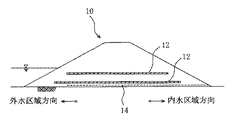
次に図面を参照して、本発明の好ましい実施の形態に係る盛土構造体について詳細に説明する。図1は、本発明の好ましい実施の形態に係る盛土構造体を示した概略図である。図1において全体として参照符号10で示される本発明の好ましい実施の形態に係る盛土構造体は、下部のほぼ全体にわたってほぼ水平方向に延びた剛性体12を備えている。剛性体12としては、鋼板、矢板などの廃棄材を防蝕加工したものが用いられる。なお、図1には、上下2つの剛性体12が示されているが、剛性体12の配置数を1基にしてもよく、3基以上にしてもよい。
Next, an embankment structure according to a preferred embodiment of the present invention will be described in detail with reference to the drawings. FIG. 1 is a schematic view showing an embankment structure according to a preferred embodiment of the present invention. The embankment structure according to a preferred embodiment of the present invention, indicated generally by the
剛性体12を盛土構造体10の下部に配置したことにより、盛土構造体10の内部において発生する応力が均一に分散され、盛土構造体10自体の不等沈下を防止することができる。
By arranging the
盛土構造体10の剛性体12の下方には、ドレーン14が配置されている。ドレーン14としては、排水マット、砂利層などが用いられる。なお、ドレーン14は、外水区域方向には延びず、内水区域方向に延びるように配置するのが好ましい。ドレーン14が外水区域方向に延びないようにしたのは、外水区域から内水区域に水が抜けないようにするためである。
A
ドレーン14を配置したことにより、地下水の間隙圧の上昇および地下水の盛土構造体10への侵入を防止し、基礎地盤の地下内において液状化が発生した場合であっても、盛土構造体10の沈下量の均等化を図り、盛土構造体10全体として変位させることができる。
By arranging the
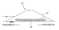
図2は、盛土構造体10の変形形態を示した概略図である。図2に示される盛土構造体20は、剛性体22として、土砂やコンクリート塊などの材料をセメントで固化したもの、又は剛性を高めるためH型鋼、鋼板、矢板などをセメントで固化したものを用いている点を除いて、盛土構造体10と実質的に同一の構成を有している。図2において、参照符号24はドレーンを示している。
FIG. 2 is a schematic view showing a modified form of the
なお、剛性体12、22を配置する範囲は、盛土構造体の設置個所の地盤の状況、使用材料の強度(弾性係数)に応じて決定される。また、ドレーン14、24を配置する範囲や材質なども、盛土構造体の設置個所の地盤の状況に応じて決定される。
In addition, the range which arrange | positions the
本発明は、以上の発明の実施の形態に限定されることなく、特許請求の範囲に記載された発明の範囲内で、種々の変更が可能であり、それらも本発明の範囲内に包含されるものであることはいうまでもない。 The present invention is not limited to the above-described embodiments, and various modifications can be made within the scope of the invention described in the claims, and these are also included in the scope of the present invention. Needless to say, it is something.
10、20 盛土構造体
12、22 剛性体
14、24 ドレーン
10, 20
Claims (3)
盛土構造体の下部のほぼ全体にわたってほぼ水平方向に延びた剛性体と、
前記剛性体の下方に配置されたドレーンとを備えていることを特徴とする盛土構造体。 An embankment structure with earthquake resistance measures,
A rigid body extending substantially horizontally across substantially the entire bottom of the embankment structure;
An embankment structure comprising a drain disposed below the rigid body.
Priority Applications (1)
| Application Number | Priority Date | Filing Date | Title |
|---|---|---|---|
| JP2004104071A JP2005290712A (en) | 2004-03-31 | 2004-03-31 | Filling structure having earthquake-resistant measures installed therein |
Applications Claiming Priority (1)
| Application Number | Priority Date | Filing Date | Title |
|---|---|---|---|
| JP2004104071A JP2005290712A (en) | 2004-03-31 | 2004-03-31 | Filling structure having earthquake-resistant measures installed therein |
Publications (1)
| Publication Number | Publication Date |
|---|---|
| JP2005290712A true JP2005290712A (en) | 2005-10-20 |
Family
ID=35323961
Family Applications (1)
| Application Number | Title | Priority Date | Filing Date |
|---|---|---|---|
| JP2004104071A Pending JP2005290712A (en) | 2004-03-31 | 2004-03-31 | Filling structure having earthquake-resistant measures installed therein |
Country Status (1)
| Country | Link |
|---|---|
| JP (1) | JP2005290712A (en) |
Cited By (3)
| Publication number | Priority date | Publication date | Assignee | Title |
|---|---|---|---|---|
| JP2008045341A (en) * | 2006-08-17 | 2008-02-28 | Railway Technical Res Inst | Construction method of embankment on soft ground and its embankment structure |
| JP2009249999A (en) * | 2008-04-11 | 2009-10-29 | Eternal Preserve Kk | Construction method for suppressing deformation of filling |
| WO2010131330A1 (en) * | 2009-05-12 | 2010-11-18 | オフィチネ マッカフェリ エス・ピー・エー | Method of suppressing deformation of embankment |
-
2004
- 2004-03-31 JP JP2004104071A patent/JP2005290712A/en active Pending
Cited By (3)
| Publication number | Priority date | Publication date | Assignee | Title |
|---|---|---|---|---|
| JP2008045341A (en) * | 2006-08-17 | 2008-02-28 | Railway Technical Res Inst | Construction method of embankment on soft ground and its embankment structure |
| JP2009249999A (en) * | 2008-04-11 | 2009-10-29 | Eternal Preserve Kk | Construction method for suppressing deformation of filling |
| WO2010131330A1 (en) * | 2009-05-12 | 2010-11-18 | オフィチネ マッカフェリ エス・ピー・エー | Method of suppressing deformation of embankment |
Similar Documents
| Publication | Publication Date | Title |
|---|---|---|
| JP5471797B2 (en) | Seismic reinforcement structure of revetment structure and existing revetment structure | |
| CN1288308C (en) | Method for constructing deep-large foundation pit over operating tunnel an ddeformation-preventing strucutre | |
| JP2005290712A (en) | Filling structure having earthquake-resistant measures installed therein | |
| JP2003232044A (en) | Cofferdam closure method | |
| JPH11209998A (en) | Impermeable construction method of underground structure by self-standing type double impermeable walls | |
| JP5959094B2 (en) | Method for forming ground improvement body | |
| CN118933037A (en) | A steel-concrete composite cofferdam suitable for vibration-sensitive areas under unbalanced earth pressure | |
| CN111021270A (en) | Construction method for permanently protecting existing pipeline during road reconstruction | |
| JP3986328B2 (en) | Ground liquefaction prevention method | |
| Brandl | Cyclic preloading of piles to minimize (differential) settlements of high-rise buildings | |
| JPH01239217A (en) | Protection method for underground structures in sandy ground prone to liquefaction | |
| JP2005016231A (en) | Liquefaction countermeasure method | |
| JP6292028B2 (en) | Embankment reinforcement structure | |
| JP6018804B2 (en) | Cell body water-blocking structure | |
| JPH01226920A (en) | Earthquake-proof construction of river embankment | |
| JP3864393B2 (en) | Construction method of river crossing structure | |
| JP2001098552A (en) | Unequal settlement preventive construction method for adjacent building in underground excavation work | |
| JP2013249660A (en) | Reinforcement method and reinforcement structure for earth retaining wall | |
| CN106836247B (en) | Combined cofferdam and construction method thereof | |
| CN222782065U (en) | Foundation pit supporting waterproof structure and engineering prefabricated supporting structure | |
| JPH03103535A (en) | Countermeasure structure for liquefaction of building | |
| CN215801679U (en) | Bias pressure foundation pit double-layer pipe pile and steel sheet pile combined enclosing structure | |
| JP2006219947A (en) | Ground excavation method | |
| JPH04131429A (en) | Underground structure | |
| Abdelrahman | Sub-structure Strengthening |
Legal Events
| Date | Code | Title | Description |
|---|---|---|---|
| A621 | Written request for application examination |
Free format text: JAPANESE INTERMEDIATE CODE: A621 Effective date: 20070207 |
|
| A977 | Report on retrieval |
Effective date: 20090123 Free format text: JAPANESE INTERMEDIATE CODE: A971007 |
|
| A131 | Notification of reasons for refusal |
Effective date: 20090130 Free format text: JAPANESE INTERMEDIATE CODE: A131 |
|
| A02 | Decision of refusal |
Effective date: 20091208 Free format text: JAPANESE INTERMEDIATE CODE: A02 |