JP2005290848A - Destructor - Google Patents
Destructor Download PDFInfo
- Publication number
- JP2005290848A JP2005290848A JP2004107577A JP2004107577A JP2005290848A JP 2005290848 A JP2005290848 A JP 2005290848A JP 2004107577 A JP2004107577 A JP 2004107577A JP 2004107577 A JP2004107577 A JP 2004107577A JP 2005290848 A JP2005290848 A JP 2005290848A
- Authority
- JP
- Japan
- Prior art keywords
- tank
- pipe
- depressurization
- merging
- outflow
- Prior art date
- Legal status (The legal status is an assumption and is not a legal conclusion. Google has not performed a legal analysis and makes no representation as to the accuracy of the status listed.)
- Pending
Links
Images
Landscapes
- Sewage (AREA)
Abstract
Description
この発明は、傾斜地に配管された下水管等に用いられて、管渠から放流される高速流水
を減勢するのに用いられる減勢工に関するものである。
The present invention relates to a depressurization method used for depressurizing high-speed running water discharged from a pipe tub and used in a sewer pipe or the like piped on an inclined land.
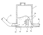
従来、図5に示すような減勢工が、知られている(例えば、特許文献1等参照)。 Conventionally, a depressurization work as shown in FIG. 5 is known (see, for example, Patent Document 1).
まず、構成から説明すると、この従来の減勢工では、傾斜地に配管された下水管3の管
路の一部には、流入口1a及び流出口1bを有する減勢槽1が設けられている。
First, from the configuration, in this conventional depressurization work, a
この減勢槽1は、内部に堰2が、前記流出口1bから所定間隔をおいて設けられている
。
In the
この堰2の下縁部近傍には、貫通孔(又はスリット)2aが形成されていて、この堰2
の上流側と下流側とを連通するように構成されている。
A through hole (or slit) 2a is formed in the vicinity of the lower edge of the weir 2 and this weir 2
The upstream side and the downstream side are configured to communicate with each other.
また、この堰2の上端縁部2bの位置は、前記流入口1aに接続される流入側の下水管
3の管底3aに対し、下水管3の管径よりも1/4以上高い位置となるように設定されて
いる。
Further, the position of the
次に、この従来の減勢工の作用について説明する。 Next, the effect | action of this conventional decelerating work is demonstrated.
このように構成された従来の減勢工では、流入側の下水管3から、この減勢槽1内に流
入した下水等の水流が、前記減勢槽1内の堰2によって上昇渦流となり、この堰2に沿っ
て、せり上がる。
In the conventional depressurization constructed as described above, the water flow such as sewage that has flowed into the
そして、この水流は、堰2の上端縁部2bを越流して、前記流出口1bから、下流側の
下水管3bを介して、流出する。
And this water flow overflows the upper
このように、この減勢槽1内に流入した水流は、前記堰2によって強制的にせり上げら
れる際に、運動エネルギが、減勢槽1の高さ方向の位置エネルギに変換されて弱まる。
As described above, when the water flow that has flowed into the
従って、傾斜地に配管される下水管3内を高速で流下する水流も、この減勢槽1内を通
過する際に減勢されて流下される。
しかしながら、このような従来の減勢工では、前記減勢槽1内に、堰2が形成されてい
るので、減勢槽1の貯水量を、この堰2の分、減少させてしまう。
However, in such a conventional depressurization work, since the weir 2 is formed in the
このため、この減勢槽1内を、貯水空間として利用する場合、貯水空間を最大限に利用
出来ないといった問題があった。
For this reason, when using the inside of this energy-
また、この減勢槽1内の貯水量を大きく設定しようとすると、越流によって、前記流出
口1bを閉塞してしまう虞があった。
Further, if the amount of water stored in the
このような前記流出口1bの閉塞を防止するため、前記減勢槽1内と、地上の外気とを
連通させる空気抜き用パイプ等を設けることも考えられるが、地表にこのような空気抜き
用パイプが、露出していると、外観品質を損ね、この減勢槽1の設置箇所が限定されてし
まうといった問題もあった。
In order to prevent such blocking of the
そこで、この発明は、貯水空間を最大限利用出来ると共に、地表に露出する部分を無く
して、設置場所の選択の自由度を向上させることが出来る減勢工を提供することを課題と
している。
Therefore, an object of the present invention is to provide a depressurizer that can make maximum use of the water storage space and can eliminate the portion exposed to the ground surface and improve the degree of freedom in selecting the installation location.
上記目的を達成するために、本願発明の請求項1記載のものは、傾斜地に配管された下
水管などの管渠から放流される高速流水を減勢するのに用いられる減勢工であって、流入
口及び流出口を有する減勢槽と、該減勢槽の下流側に位置する合流部とを、前記流入口の
管底部よりも高い位置に設けられる流出口に接続される流出本管によって接続する減勢工
を特徴としている。
In order to achieve the above object, the invention according to
また、請求項2に記載されたものは、前記合流部には、前記減勢槽と略同じ大きさの容
量を有する合流槽を設けた請求項1記載の減勢工を特徴としている。
In addition, what is described in claim 2 is characterized in that the merging section is provided with a merging tank having a capacity substantially the same as that of the dying tank in the merging portion.
更に、請求項3に記載されたものは、前記合流部には、前記流出本管と直接合流する支
管を有して構成されている請求項1記載の減勢工を特徴としている。
Further, what is described in
また、請求項4に記載されたものは、前記減勢槽内の空間部と前記合流槽内の空間部と
を連通する通気排気管が設けられている請求項2記載の減勢工を特徴としている。
In addition, what is described in claim 4 is characterized in that a ventilating exhaust pipe is provided which communicates the space portion in the depressurization tank and the space portion in the merge tank. It is said.
そして、請求項5に記載されたものは、前記下流側に位置する合流部への流出口が、前
記減勢槽の流入口形成位置に対して、前記流出口形成位置が対向しないように、平面視で
一定角度で該減勢槽の側壁部に形成されている請求項1乃至4記載の減勢工を特徴として
いる。
And what was described in Claim 5 is that the outflow port to the confluence | merging part located in the said downstream is such that the said outflow port formation position does not oppose with respect to the inflow port formation position of the said depressurization tank, 5. The pressure reducing means according to
このように構成された請求項1記載のものは、減勢槽内に前記流入口から流入した高速
の水流は、前記流出口周縁の該減勢槽の内壁部に当接して、勢いを弱められてから、せり
上がり、前記流入口の管底部よりも高い位置に設けられる該流出口から、前記流出本管内
へ流出される。
According to the first aspect of the present invention, the high-speed water flow that has flowed from the inflow port into the depressurization tank comes into contact with the inner wall portion of the depressurization tank at the periphery of the outflow port to weaken the momentum. Then, it rises and flows out into the outflow main pipe from the outlet provided at a position higher than the pipe bottom of the inlet.
このため、従来の様に、減勢槽内に堰を設ける必要が無く、該減勢槽内を、貯水空間と
して利用する場合、貯水空間を最大限に利用することが出来る。
For this reason, unlike the conventional case, there is no need to provide a weir in the energy reducing tank, and when the inside of the energy reducing tank is used as a water storage space, the water storage space can be utilized to the maximum extent.
また、請求項2に記載されたものは、前記減勢槽の下流側に位置する前記合流部には、
前記減勢槽と略同じ大きさの容量を有する合流槽が設けられている。
Moreover, what was described in Claim 2 is in the said junction part located in the downstream of the said depressurization tank,
A merging tank having a capacity of approximately the same size as the depressurization tank is provided.
このため、該合流部の合流槽内の空間部容積も、貯水空間として利用する場合、貯水空
間を、更に、増大させることが出来る。
For this reason, when the space part volume in the merging tank of the merging part is also used as the water storage space, the water storage space can be further increased.
しかも、略同じ形状に形成すれば、該減勢槽と該合流槽とを共通のマンホール等によっ
て構成することも出来、製造コストの増大を抑制出来る。
And if it forms in the substantially same shape, this depressurization tank and this merge tank can also be comprised by a common manhole etc., and the increase in manufacturing cost can be suppressed.
更に、請求項3に記載されたものは、前記合流部が、前記流出本管と直接合流する支管
を有して構成されている。
Further, the present invention is configured such that the merging portion has a branch pipe that directly merges with the outflow main pipe.
このため、合流槽を配置出来ないような場所でも、貯水空間量を最大限に利用すること
ができる減勢工を施工できる。
For this reason, even in a place where the merging tank cannot be arranged, it is possible to construct a depressurization work that can make maximum use of the water storage space.
また、請求項4に記載されたものは、前記減勢槽内の空間部と前記合流槽内の空間部と
が、通気排気管によって、連通されている。
According to a fourth aspect of the present invention, the space part in the depressurization tank and the space part in the merging tank are communicated with each other by a ventilation exhaust pipe.
このため、万一、水流によって、前記流出口が閉塞されてしまうような場合でも、地表
に露出される空気抜き用パイプ等を設けることなく、該減勢槽内の空気を前記合流槽内に
逃がして、該減勢槽内の内圧によって、流下する水流の流入が妨げられる虞を無くすこと
ができる。
For this reason, even if the outlet is blocked by a water flow, the air in the depressurization tank is allowed to escape into the merging tank without providing an air vent pipe exposed on the ground surface. Thus, it is possible to eliminate the possibility that the inflow of the flowing water is hindered by the internal pressure in the depressurization tank.
しかも、地表に露出されるような空気抜き用パイプが不要となるので、設置場所の選択
の自由度を向上させることが出来る。
In addition, since an air vent pipe that is exposed on the ground surface is not required, the degree of freedom in selecting the installation location can be improved.
そして、請求項5に記載されたものは、前記流出口形成位置が、該減勢槽の側壁部に前
記減勢槽の流入口形成位置に対して、対向しないように、平面視で一定角度で形成されて
いる。
Further, according to a fifth aspect of the present invention, the outlet forming position is at a constant angle in plan view so as not to face the inlet port forming position of the depressing tank to the side wall portion of the depressing tank. It is formed with.
このため、前記減勢槽による減勢効果を発揮させつつ、該減勢槽で、前記傾斜地に配管
された下水管などの配管方向を変えることが出来る。
For this reason, it is possible to change the piping direction of the sewage pipe or the like piped to the sloping ground in the power reducing tank while exhibiting the power reducing effect by the power reducing tank.
従って、下水管は、直線状の直管パイプを使用出来て、更に、配管が容易である。 Therefore, a straight straight pipe can be used as the sewage pipe, and the piping is easy.
次に、図面に基づいて、この発明を実施するための最良の実施の形態の減勢工を説明す
る。
Next, based on the drawings, a destructive work of the best mode for carrying out the present invention will be described.
なお、前記従来例と同一乃至均等な部分については同一符号を付して説明する。 In addition, the same code | symbol is attached | subjected and demonstrated about the same or equivalent part as the said prior art example.
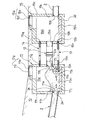
図1乃至図4は、この発明の最良の実施の形態の減勢工を示している。 FIG. 1 to FIG. 4 show a derating process according to the preferred embodiment of the present invention.
まず、この実施の形態の減勢工の構成を説明すると、この実施の形態の減勢工では、傾
斜地に配管された下水管3などの管渠の管路の一部には、地中10に埋設されて、この管
渠から放流される高速流水を減勢するのに用いられる減勢槽11が、流入口11a及び流
出口11bを有して設けられている。
First, a description will be given of the configuration of the depressurization work of this embodiment. In the depressurization work of this embodiment, a part of the pipe line of the sewer pipe such as the
この発明の実施例1では、前記減勢槽11が、略円柱形形状のマンホール本体11cに
よって、主に構成されている。
In the first embodiment of the present invention, the
このマンホール本体11cは、内部に水を貯水する貯水空間部11dが形成されている
と共に、上部に点検用開口部11eを開閉可能な蓋体11fが設けられたマンホール部1
1gが形成されている。
The
1 g is formed.
また、この実施例1の減勢槽11には、前記貯水空間部11dの相互に反対側に位置す
る対向壁面部11h,11iに、各々前記流入口11a及び流出口11bが開口形成され
ている。
Further, in the
このうち、前記流入口11aには、流入側の下水管3が、一定の傾斜角度を有して接続
されている。
Among these, the inflow
また、この下水管3の管底3aと同じ高さに位置する前記流入口11aの管底部11j
よりも高い位置には、前記流出口11bの管底部11kが設けられていて、この流出口1
1bに略水平に接続される流出本管12の管底部12aの位置が、前記管底3aの位置よ
りも高くなるように設定されている。
Further, the
A
The position of the
この実施例1では、この流出本管12の管径は、前記下水管3の管径と略同じになるよ
うに設定されている。
In the first embodiment, the pipe diameter of the outflow
更に、この実施例1では、前記流出本管12の管底部12aの位置が、前記下水管3の
流入口接続端縁部の管上縁3cの位置と略同じか、或いは高くなるように設定されている
。
Further, in the first embodiment, the position of the
また、この減勢槽11の底面部には、前記管底3aの位置と略同じ高さ位置の平坦な上
面を有する底上げ部11mが設けられている。
Further, a
更に、前記対向壁面部11iには、前記管底3aの位置と略同じ高さ位置に管底を有す
る支管13が、挿通される支管挿通孔11nが設けられている。この支管13は、前記流
出本管12及び、前記下水管3の管径よりも小さい管径を有して構成されている。
Further, the opposed
また、この実施例1の前記対向壁面部11iの前記底上げ部11m近傍の下端面には、
この貯水空間部11d内に流入した水流を上昇渦流とする一定の角度の傾斜面からなる傾
斜当接面部11pが形成されている。
Moreover, on the lower end surface in the vicinity of the bottom raised
An inclined
そして、この傾斜当接面部11pから、前記支管13の斜めに形成された先端縁部13
aを前記貯水空間部11d内に臨ませることにより連通するように構成されている。
And the
It is comprised so that it may communicate by making a enter the said water
また、この対向壁面部11iには、前記流出口11bと一定距離離間された上方位置に
、通気排気管14が接続される通気孔11qが、開口形成されている。
Further, a vent hole 11q to which the
この通気排気管14は、前記流出本管12及び、前記下水管3の管径よりも小さい管径
で、しかも、前記支管13と略同じ管径を有して構成されている。
The
そして、前記流出本管12,支管13及びこの通気排気管14は、そのまま略水平に延
設されて、前記減勢槽11の下流側に一定距離を置いて位置して、この実施例1の合流部
としての合流槽15に接続されることにより、各々連通されている。
The outflow
この合流槽15は、前記減勢槽11の貯水空間部11dと、略同じ大きさの容量を有す
る合流空間部15dを内部に有するマンホール本体15cを有して、主に構成されている
。
The merging
このマンホール本体15cの上部には、点検用開口部15eを開閉可能な蓋体15fが
設けられたマンホール部15gが形成されている。
A manhole portion 15g provided with a lid 15f capable of opening and closing the inspection opening 15e is formed on the upper portion of the
また、この実施例1の合流槽15には、前記流出本管12,支管13及びこの通気排気
管14の各下流側端縁を各々連通させて接続する流入口15a,支管接続孔15n及び通
気孔15qが、対向壁面部15hに開口形成されている。
Further, in the merging
そして、この対向壁面部15hの前記合流空間部15dを挟んで反対側に位置する対向
壁面部15iには、流出口15bが開口形成されている。
And the
この流出口15bには、下流側の下水管3が、管底3dを前記支管接続孔15n内に位
置する支管13の管底13bと略同一高さとなるように接続されている。
The
この実施例1では、この流出本管12の管径が、この下流側の前記下水管3の管径とも
略同じになるように設定されている。
In the first embodiment, the pipe diameter of the outflow
そして、この実施例1では、この合流槽15の底面部には、前記管底3d及び支管13
の管底13b位置と略同じ高さ位置の平坦な上面を有する底上げ部15mが設けられてい
る。
And in this Example 1, in the bottom face part of this merging
A bottom raised
次に、この実施例1の減勢工の作用について説明する。 Next, the effect | action of the de-energization work of this Example 1 is demonstrated.
この実施例1の減勢工では、傾斜地に配管された上流側の下水管3から、前記減勢槽1
1の貯水空間部11d内に、前記流入口11aを介して、高速の水流が流入する。
In the depressurization work of this Example 1, from the
A high-speed water flow flows into the one water
この水流は、前記流出口11b周縁のこの減勢槽11の内壁部である対向壁面部11i
に当接して、勢いを弱められると共に、前記一定の角度の傾斜面からなる傾斜当接面部1
1pによって、貯水空間部11d内に流入した水流が上昇渦流となって、せり上がる。
This water flow is the opposite
The inclined
By 1p, the water flow that flows into the water
そして、前記流入口11a内の管底部11jよりも高い位置に設けられるこの流出口1
1bから、前記流出本管12内へ勢いが弱められた水流が流出される。
And this
From 1b, the water flow with reduced momentum flows into the outflow
このため、従来の図5に示すものの様に、前記減勢槽1内に堰2を設ける必要が無く、
この減勢槽11内の貯水空間部11dを、貯水空間として利用する場合、貯水空間を最大
限に利用することが出来る。
Therefore, unlike the conventional one shown in FIG. 5, there is no need to provide the weir 2 in the
When the water
また、流入により、一旦、この減勢槽11内の貯水空間部11dに貯水された流水は、
前記支管13を介して、前記合流槽15内の合流空間部15dに移動して、前記流出本管
12によって、流入した流水と合流する。
Moreover, the flowing water once stored in the water
It moves to the merging
そして、前記流出口15bを介して、下水管3方向に排水される。
And it drains to the
また、前記減勢槽11の下流側に位置する前記合流部としての合流槽15には、前記減
勢槽11の貯水空間部11dと略同じ大きさの容量を有する合流空間部15dが設けられ
ている。
In addition, a merging
このため、この合流槽15内の合流空間部15d内容積も、貯水空間として利用する場
合、貯水空間を、更に、増大させることが出来る。
For this reason, when the internal volume of the
しかも、この実施例1では、これらの減勢槽11及び合流槽15が、略同じ形状に形成
されている。このため、減勢槽11と合流槽15とを共通のマンホール等によって構成す
ることも出来、製造コストの増大を抑制出来る。
Moreover, in the first embodiment, the
また、この実施例1では、前記減勢槽11内の貯水空間部11dと前記合流槽15内の
合流空間部15dとが、前記通気排気管14によって、連通されている。
Further, in the first embodiment, the water
このため、万一、水流によって、前記流出口11bが閉塞されてしまうような場合でも
、地表に露出される空気抜き用パイプ等を設けることなく、この減勢槽11内の空気を、
この通気排気管14によって、前記合流槽15内に逃がして、減勢槽11内の内圧によっ
て、流下する水流の流入が妨げられる虞を無くすことができる。
For this reason, even if the
This
しかも、地表に露出されるような空気抜き用パイプが不要となるので、設置場所の選択
の自由度を向上させることが出来る。
In addition, since an air vent pipe that is exposed on the ground surface is not required, the degree of freedom in selecting the installation location can be improved.
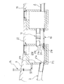
図2は、この実施の形態の実施例2の減勢工を示すものである。 FIG. 2 shows the derating work of Example 2 of this embodiment.
なお、前記実施例1の減勢工と、同一乃至均等な部分については、同一符号を付して説
明する。
In addition, the same code | symbol is attached | subjected and demonstrated about the same or equivalent part as the depressurization work of the said Example 1. FIG.
まず、構成上の相違点から説明すると、この実施例2の減勢工では、実施例1の前記通
気排気管14に代えて、前記貯水槽11の貯水空間部11d内の空気を逃がすように、地
表9に立設されて、貯水空間部11d内と連通される空気抜き用パイプ部24が、一方の
対向壁面部21hに接続されて設けられている。
First, to explain the difference in configuration, in the depressurization work of the second embodiment, air in the water
次に、この実施例2の減勢工の作用について説明する。 Next, the operation of the de-energizing work of Example 2 will be described.
このように構成された実施例2の減勢工では、前記実施例1の減勢工の作用効果に加え
て、更に、万一、水流によって、流出口21bが閉塞されてしまうような場合でも、地表
に露出される空気抜き用パイプ部24を介して、この減勢槽21内の空気が、大気に逃が
される。
In the energy reducing work of the second embodiment configured as described above, in addition to the effect of the power reducing work of the first embodiment, even in the case where the
このため、前記減勢槽21内の内圧によって、流下する水流の流入が妨げられる虞を無
くすことができる。
For this reason, it is possible to eliminate the possibility that the inflow of the flowing water is hindered by the internal pressure in the
また、前記空気抜き用パイプ部24は、安価に設置出来るので、製造コストの上昇を抑
制できる。
Moreover, since the said air
他の構成、及び作用効果については、前記実施例1と略同様であるので、説明を省略す
る。
Other configurations and operational effects are substantially the same as those of the first embodiment, and thus the description thereof is omitted.
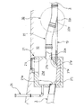
図3は、この実施の形態の実施例3の減勢工を示すものである。 FIG. 3 shows the depressurization work of Example 3 of this embodiment.
なお、前記実施例1,2の減勢工と、同一乃至均等な部分については、同一符号を付し
て説明する。
In addition, the same code | symbol is attached | subjected and demonstrated about the same or equivalent part as the depressurization work of the said Examples 1,2.
まず、構成から説明すると、この実施例3の減勢工では、前記合流部30が、前記減勢
槽21に接続される流出本管22と直接合流する支管13を有して主に、構成されている
。
First, in terms of the configuration, in the de-energization work of the third embodiment, the merging
この実施例3の合流部30では、前記流出本管22の下側外側面部22cに、前記支管
13が挿通される挿通孔22dが開口形成されると共に、この挿通孔22dに、前記支管
13が、挿通されて接続されることにより、直接合流されるように構成されている。
In the merging
次に、この実施例3の減勢工の作用について説明する。 Next, the operation of the de-energizing work of the third embodiment will be described.
このように構成された実施例3の減勢工では、前記合流部30が、前記流出本管22と
直接合流する支管13を有して構成されている。
In the de-energizing work of Example 3 configured as described above, the merging
このため、傾斜地に配管された上流側の下水管3から、前記減勢槽21の貯水空間部2
1d内に、高速の水流が流入すると、前記流出口21b周縁の対向壁面部21iに当接し
て、勢いを弱められると共に、前記一定の角度の傾斜面からなる傾斜当接面部21pによ
って、貯水空間部21d内に流入した水流が上昇渦流となって、せり上がる。
For this reason, from the
When a high-speed water flow flows into 1d, it is brought into contact with the opposing
そして、前記流入口21a内の管底部21jよりも高い位置に設けられるこの流出口2
1bの管底部21kから、前記流出本管22内へ、勢いが弱められた水流が流出される。
And this outflow port 2 provided at a position higher than the
From the
このため、従来の図5に示すものの様に、前記減勢槽1内に堰2を設ける必要が無く、
この減勢槽21内の貯水空間部21dを、貯水空間として利用する場合、貯水空間を最大
限に利用することが出来る。
Therefore, unlike the conventional one shown in FIG. 5, there is no need to provide the weir 2 in the
In the case where the water
また、流入により、一旦、この減勢槽21内の貯水空間部21dに貯水された流水は、
前記支管13を介して、前記合流部30で、前記流出本管22と合流する。
Also, the flowing water once stored in the water
The merging
そして、この流出本管22の合流部30よりも下流側の下水管3方向に排水される。
And it drains in the direction of the
従って、前記実施例1に記載された合流槽15を配置出来ないような場所でも、前記減
勢槽21の貯水空間部21d内の容積を用いて、貯水空間量を最大限に利用することがで
きる減勢工を施工できる。
Therefore, even in a place where the merging
他の構成、及び作用効果については、前記実施例1,2と略同様であるので、説明を省
略する。
Other configurations and operational effects are substantially the same as those of the first and second embodiments, and thus the description thereof is omitted.
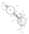
図4は、この実施の形態の実施例4の減勢工を示すものである。 FIG. 4 shows the depressurization work of Example 4 of this embodiment.
なお、前記実施例1乃至2の減勢工と、同一乃至均等な部分については、同一符号を付
して説明する。
In addition, the same code | symbol is attached | subjected and demonstrated about the same or equivalent part as the depressurization work of the said Examples 1-2.
まず、構成から説明すると、この実施例4の減勢工では、図4に示すように、前記下流
側に位置する合流槽15への流出口11bが、前記減勢槽11の流入口11a形成位置に
対して、前記流出口11b形成位置が、正面に対向しないように、平面視で一定の角度で
、この減勢槽11の側壁部11rに形成されている。
First, from the configuration, in the de-energizing work of the fourth embodiment, as shown in FIG. 4, the
このため、前記下水管3の管軸方向S3に対して、流出本管12の管軸方向S12が、
一定の角度α(α=約−90〜+90度、この実施例4では、α=約45度)を形成して
、各々前記減勢槽11に接続されるように構成されている。
For this reason, the pipe axis direction S12 of the outflow
A fixed angle α (α = about −90 to +90 degrees, in this embodiment 4, α = about 45 degrees) is formed, and each is connected to the
更に、この実施例4では、前記流出本管12,支管13及びこの通気排気管14が、高
さ方向では、一定間隔をおいて離間されると共に、図4に示すように、平面視では、重ね
られて延設されている。
Furthermore, in the fourth embodiment, the outflow
次に、この実施例4の減勢工の作用について説明する。 Next, the operation of the de-energizing work of Example 4 will be described.
このように構成された実施例4の減勢工では、前記実施例1の減勢工の作用効果に加え
て、更に、前記流出口11bの形成位置が、前記減勢槽11の側壁部11rに、前記減勢
槽11の流入口11a形成位置に対して、正面で対向しないように、平面視で一定角度α
を与えられて形成されている。
In the depressurization work of the fourth embodiment configured as described above, in addition to the effect of the depressurization work of the first embodiment, the formation position of the
Is formed.
このため、前記減勢槽11内では、貯水空間部11dの対向壁面部11iに、水流を当
接させて、減勢効果を発揮させつつ、前記流出口11bに接続された流出本管12へ、勢
いの弱まった水流を流下させることができる。
For this reason, in the
そして、この減勢槽11で、前記傾斜地に配管された下水管3,3の配管方向を変える
ことが出来る。
And in this
また、前記下水管3,3及び前記流出本管12,支管13及び通気排気管14は、直線
状の直管パイプを使用出来て、更に、製造コストの増大を抑制できる。
Further, the
更に、この実施例4では、前記流出本管12,支管13及びこの通気排気管14が、高
さ方向では、一定間隔をおいて離間されると共に、図4に示すように、平面視では、重ね
られて延設されている。
Furthermore, in the fourth embodiment, the outflow
このため、前記減勢槽11と合流槽15との間に、配管用の縦溝を掘削する際にも、最
も管径の大きい流出本管12の幅の縦溝を掘り下げれば、全ての前記流出本管12,支管
13及び通気排気管14を容易に埋設できる。
For this reason, when excavating a vertical groove for piping between the
従って、配管施工を容易として、更に、製造コストの増大を抑制できる。 Therefore, it is possible to facilitate the piping construction and further suppress an increase in manufacturing cost.
以上、図面を参照して、本発明の実施の形態を詳述してきたが、具体的な構成は、この
実施の形態に限らず、本発明の要旨を逸脱しない程度の設計的変更は、本発明に含まれる
。
The embodiment of the present invention has been described in detail above with reference to the drawings. However, the specific configuration is not limited to this embodiment, and design changes that do not depart from the gist of the present invention are not limited to this embodiment. Included in the invention.
即ち、前記実施例1では、前記減勢槽11の底面部には、前記管底3d及び支管13の
管底13b位置と略同じ高さ位置の平坦な上面を有する底上げ部15mが設けられている
と共に、一定の角度の傾斜面からなる傾斜当接面部11pが形成されているが、特にこれ
に限らず、例えば、何れか一方が、設けられているか若しくは、両方とも設けられていな
くてもよい。
That is, in the first embodiment, the bottom surface portion of the
更に、前記実施1及び実施例2では、前記通気排気管14及び空気抜き用パイプ部24
が選択的に、何れか一つ設けられているものを用いて、説明してきたが、特にこれに限ら
ず、前記通気排気管14及び空気抜き用パイプ部24の何れもが、設けられていても良い
ことは当然である。
Further, in the first and second embodiments, the
However, the present invention is not limited to this, and any of the
3 下水管
3a 管底
11,21 減勢槽
11a,21a 流入口
11b,21b 流出口
11d,21d 貯水空間部
11i,21i 対向壁面部
11j,21j 管底部(流入口側の)
11k,21k 管底部(流出口側の)
11r 側壁部
12,22 流出本管
12a,22a 管底部
13 支管
30 合流部
3
11k, 21k Tube bottom (outlet side)
11r
Claims (5)
る減勢工であって、
流入口及び流出口を有する減勢槽と、該減勢槽の下流側に位置する合流部とを、前記流
入口の管底部よりも高い位置に設けられる流出口に接続される流出本管によって接続する
ことを特徴とする減勢工。 A de-energizing work used to de-energize high-speed running water discharged from pipes such as sewage pipes piped on slopes,
An outflow main pipe connected to an outflow port provided at a position higher than the tube bottom of the inflow port, a depressurization tank having an inflow port and an outflow port, and a joining portion located downstream of the depressurization tank. Reducer characterized by connecting.
とする請求項1記載の減勢工。 2. The de-energizing work according to claim 1, wherein the merging section is provided with a merging tank having a capacity substantially the same as that of the derating tank.
とする請求項1記載の減勢工。 2. The de-energizing work according to claim 1, wherein the confluence portion includes a branch pipe that directly merges with the outflow main pipe.
ることを特徴とする請求項2記載の減勢工。 The ventilating / exhausting pipe according to claim 2, further comprising a ventilation exhaust pipe that communicates the space part in the derating tank and the space part in the merging tank.
記流出口形成位置が対向しないように、平面視で一定角度で該減勢槽の側壁部に形成され
ていることを特徴とする請求項1乃至4記載の減勢工。
A side wall of the pressure reducing tank at a constant angle in plan view so that the outlet to the junction located on the downstream side does not face the inlet forming position of the power reducing tank. The depressurizer according to claim 1, wherein the depressurizer is formed in a portion.
Priority Applications (1)
| Application Number | Priority Date | Filing Date | Title |
|---|---|---|---|
| JP2004107577A JP2005290848A (en) | 2004-03-31 | 2004-03-31 | Destructor |
Applications Claiming Priority (1)
| Application Number | Priority Date | Filing Date | Title |
|---|---|---|---|
| JP2004107577A JP2005290848A (en) | 2004-03-31 | 2004-03-31 | Destructor |
Publications (1)
| Publication Number | Publication Date |
|---|---|
| JP2005290848A true JP2005290848A (en) | 2005-10-20 |
Family
ID=35324094
Family Applications (1)
| Application Number | Title | Priority Date | Filing Date |
|---|---|---|---|
| JP2004107577A Pending JP2005290848A (en) | 2004-03-31 | 2004-03-31 | Destructor |
Country Status (1)
| Country | Link |
|---|---|
| JP (1) | JP2005290848A (en) |
-
2004
- 2004-03-31 JP JP2004107577A patent/JP2005290848A/en active Pending
Similar Documents
| Publication | Publication Date | Title |
|---|---|---|
| JP5628384B2 (en) | Vortex prevention device and pump device | |
| JP6921693B2 (en) | Drainage piping system | |
| JP6953317B2 (en) | Pump with vortex suppressor | |
| JP2009047082A (en) | Suction tank and pump gate | |
| CN103615578A (en) | Anti-backflow check valve | |
| JP2005290848A (en) | Destructor | |
| CN204435497U (en) | A kind of eddy flow H of draining band inspection hole manages | |
| JP4566852B2 (en) | Horizontal axis pump, pump gate equipment, drainage station | |
| ES2668859T3 (en) | Swirl flow type water surface control device for drainage system | |
| CN101413327A (en) | Emergency drain for draining a surface | |
| CN201614635U (en) | A drain valve base | |
| JP2009299308A (en) | Back flow preventing structure and drainage facility | |
| JP5566571B2 (en) | Drain socket | |
| JP4628029B2 (en) | Rectifying member of submersible pump for pump gate | |
| JP5324855B2 (en) | Siphon drainage system | |
| KR20110019911A (en) | Euro variable drainage check | |
| JP5085961B2 (en) | Siphon drainage system | |
| CN201704749U (en) | Plug for intercepting litters | |
| CN103949138A (en) | Absorption tower for preventing flue gas from flowing backward and application thereof | |
| CN201080653Y (en) | Waterspout guard | |
| JP6731292B2 (en) | Negative pressure suction toilet | |
| JP6688541B2 (en) | Drain trap, interceptor with drain trap | |
| JP5324853B2 (en) | Siphon drainage system | |
| JP2005171685A (en) | Drainage piping system and bent joint | |
| JP2807178B2 (en) | Drainage collecting pipe |