JP2005291356A - Method and system for analyzing rolling bearing - Google Patents
Method and system for analyzing rolling bearing Download PDFInfo
- Publication number
- JP2005291356A JP2005291356A JP2004106881A JP2004106881A JP2005291356A JP 2005291356 A JP2005291356 A JP 2005291356A JP 2004106881 A JP2004106881 A JP 2004106881A JP 2004106881 A JP2004106881 A JP 2004106881A JP 2005291356 A JP2005291356 A JP 2005291356A
- Authority
- JP
- Japan
- Prior art keywords
- rolling bearing
- analysis
- load
- rolling
- contact
- Prior art date
- Legal status (The legal status is an assumption and is not a legal conclusion. Google has not performed a legal analysis and makes no representation as to the accuracy of the status listed.)
- Granted
Links
Images


Landscapes
- Rolling Contact Bearings (AREA)
- Shafts, Cranks, Connecting Bars, And Related Bearings (AREA)
Abstract
【課題】シャフトが結合されて変動負荷を受ける状態における転がり軸受の挙動を充分な解析精度で簡便に解析する。
【解決手段】転がり軸受におけるボール44の位置と、該ボール44における接触点を含むアキシャル平面である仮想断面S2を特定する(ステップS5)。ボール44の仮想断面S2上における接触荷重fiを求める(ステップS6)。ボール44の仮想断面S2上における減衰を求める(ステップS7)。各ボール44について仮想断面S2、接触荷重fi及び減衰を求めた後(ステップS8)、各接触荷重fi及び各減衰を合成して合成荷重ベクトルF及び合成トルクベクトルTを求める(ステップS9)。合成荷重ベクトルF及び合成トルクベクトルTから6軸周りの荷重を求める(ステップS10)。
【選択図】図7
An object of the present invention is to simply analyze the behavior of a rolling bearing in a state where a shaft is coupled and subjected to a variable load with sufficient analysis accuracy.
A position of a ball 44 in a rolling bearing and a virtual cross section S2 which is an axial plane including a contact point on the ball 44 are specified (step S5). Request contact load f i on the virtual cross section S2 of the ball 44 (step S6). The attenuation of the ball 44 on the virtual cross section S2 is obtained (step S7). Virtual sectional S2 for each ball 44, after obtaining the contact load f i and damping (step S8), and combines the contact load f i and the attenuation seek combined load vector F and combined torque vector T (step S9) . A load around six axes is obtained from the combined load vector F and the combined torque vector T (step S10).
[Selection] Figure 7
Description
本発明は、転がり軸受にシャフトが取り付けられた状態で、該シャフトに外力が作用する際の変位及び歪み等を解析するための転がり軸受の解析方法及び解析システムに関する。 The present invention relates to an analysis method and an analysis system for a rolling bearing for analyzing displacement and distortion when an external force is applied to the shaft in a state where the shaft is attached to the rolling bearing.
エンジン開発におけるクランクシャフトの機構解析は、設計初期段階から重要視されており、このための機構解析技術が提案されている(例えば、非特許文献1参照)。また、多気筒型のエンジンにおけるクランクシャフトへの負荷増大を低減させるための設計方法が提案されている(例えば、特許文献1参照)。 The mechanism analysis of the crankshaft in engine development is regarded as important from the initial design stage, and a mechanism analysis technique for this purpose has been proposed (for example, see Non-Patent Document 1). In addition, a design method for reducing an increase in load on a crankshaft in a multi-cylinder engine has been proposed (see, for example, Patent Document 1).
これらの技術及び方法で想定されているエンジンは多気筒型であって、クランクシャフトは滑り軸受により軸支されている。 The engine assumed in these techniques and methods is a multi-cylinder type, and the crankshaft is supported by a sliding bearing.
一方、単気筒小型エンジン等の組立型クランクシャフトは転がり軸受によって軸支されているものがある。このようなクランクシャフトの挙動解析には軸支する転がり軸受の挙動も解析する必要がある。転がり軸受の挙動に関しては種々の論文が発表されている(例えば、非特許文献2、非特許文献3参照)。
On the other hand, some assembled crankshafts such as single cylinder small engines are supported by rolling bearings. In order to analyze the behavior of such a crankshaft, it is also necessary to analyze the behavior of a rolling bearing supported by the shaft. Various papers have been published regarding the behavior of rolling bearings (see, for example, Non-Patent
前記の特許文献1及び非特許文献1に記載されている方法及び技術は多気筒エンジンで、クランクシャフトの軸受に滑り軸受を用いているエンジンのための解析に用いられるものであり、小型エンジン等で転がり軸受により軸支されているクランクシャフトの解析に適用することは困難である。
The methods and techniques described in
また、前記の非特許文献2及び非特許文献3に記載されている解析方法は、軸受単体の解析を行うための方法であり、クランクシャフトを含んだ機構全体の解析やクランクシャフトに変動荷重をうける場合の解析に適用することは困難である。
The analysis methods described in
一方、転がり軸受の解析方法としては、従来から線形及び非線形の単純なばね・ダンパモデルが用いられているが、このようなモデルは、クランクシャフトのような変動荷重を受けるシャフトを軸支する転がり軸受の解析に対しては解析精度が不十分である。また、転がり軸受の3次元的幾何形状から各部の接触を判断して個々の転動体における荷重を求めるという詳細接触解析手法を適用するためには膨大な計算時間を要し、実用的とはいえない。 On the other hand, linear and non-linear simple spring / damper models have been conventionally used as analysis methods for rolling bearings. Such models, however, are rolling bearings that support shafts subject to fluctuating loads such as crankshafts. The analysis accuracy is insufficient for the analysis of bearings. Moreover, enormous calculation time is required to apply the detailed contact analysis method in which the contact of each part is determined from the three-dimensional geometric shape of the rolling bearing and the load on each rolling element is obtained. Absent.
本発明はこのような課題を考慮してなされたものであり、クランクシャフト等のシャフトが結合されて変動負荷を受ける状態における転がり軸受の挙動を簡便に解析することができ、しかも充分な解析精度を有する転がり軸受の解析方法及び解析システムを提供することを目的とする。 The present invention has been made in consideration of such problems, and can easily analyze the behavior of a rolling bearing in a state in which a shaft such as a crankshaft is coupled to receive a variable load, and has sufficient analysis accuracy. An object of the present invention is to provide an analysis method and an analysis system for a rolling bearing having the following.
本発明に係る転がり軸受の解析方法は、略同軸の内輪及び外輪と、前記内輪と前記外輪の間に転がり可能に設けられた複数の転動体とを有する転がり軸受の解析方法において、前記各転動体の仮想断面上における接触荷重を求める工程と、前記各接触荷重を合成して合成荷重ベクトル及び合成トルクベクトルを求める工程と、を有することを特徴とする。 A rolling bearing analysis method according to the present invention includes a rolling bearing analysis method including a substantially coaxial inner ring and outer ring, and a plurality of rolling elements provided between the inner ring and the outer ring so as to allow rolling. And a step of obtaining a contact load on a virtual cross section of the moving body and a step of obtaining a combined load vector and a combined torque vector by combining the contact loads.
また、本発明に係る転がり軸受の解析システムは、略同軸の内輪及び外輪と、前記内輪と前記外輪の間に転がり可能に設けられた複数の転動体とを有する転がり軸受の解析システムにおいて、前記各転動体のアキシャル平面上における接触荷重を求める手段と、前記各接触荷重を合成して合成荷重ベクトル及び合成トルクベクトルを求める手段と、を有し、前記アキシャル平面は、前記転動体が前記内輪又は前記外輪と接触する接触点を含む平面であることを特徴とする。 Further, the rolling bearing analysis system according to the present invention is a rolling bearing analysis system comprising a substantially coaxial inner ring and outer ring, and a plurality of rolling elements provided so as to be able to roll between the inner ring and the outer ring. Means for obtaining a contact load on the axial plane of each rolling element, and means for obtaining a combined load vector and a combined torque vector by synthesizing the respective contact loads, wherein the rolling element includes the inner ring Or it is a plane containing the contact point which contacts the said outer ring | wheel, It is characterized by the above-mentioned.
このように、各転動体の仮想断面上における接触荷重を合成して合成荷重ベクトル及び合成トルクベクトルを求めることにより、シャフトが結合されて変動負荷を受ける状態における転がり軸受の挙動を解析することができ、しかも充分な解析精度を有する。転動体は3次元的で複雑な接触に基づいて公転運動するが、上記の方法により転動体の運動を仮想断面上の2次元平面における運動に置き換えることができ、接触荷重精度を維持したまま簡便に解析することができる。 As described above, by combining the contact loads on the virtual cross section of each rolling element to obtain the combined load vector and the combined torque vector, it is possible to analyze the behavior of the rolling bearing in a state where the shaft is coupled and subjected to the variable load. It is possible and has sufficient analysis accuracy. The rolling element revolves based on a three-dimensional and complex contact, but the above method can replace the rolling element's movement with a two-dimensional plane on a virtual cross section, and it is easy to maintain contact load accuracy. Can be analyzed.
この場合、前記仮想断面は、前記転動体が前記内輪又は前記外輪と接触する接触点を含むアキシャル平面であると、より正確な解析を行うことができる。 In this case, when the virtual cross section is an axial plane including a contact point where the rolling element contacts the inner ring or the outer ring, a more accurate analysis can be performed.
また、前記接触荷重は関数で求められ、該関数は解析プログラムにソルバとして組み込まれると、解析プログラムと協動的に解析処理を行うことができる。 The contact load is obtained as a function, and when the function is incorporated as a solver in the analysis program, the analysis process can be performed in cooperation with the analysis program.
前記転がり軸受の弾性的な特性を含む有限要素法モデルに対して前記合成荷重ベクトル及び前記合成トルクベクトルを作用させ、前記転がり軸受又は該転がり軸受に軸支されるシャフトの所定の箇所における変位又は歪みを求めてもよい。有限要素法モデルによれば、実績のある従来の解析ツールを適用して簡便に解析を行うことができる。変位又は歪みを求めることにより、転がり軸受、シャフト等の評価を適切に行うことができる。 The combined load vector and the combined torque vector are applied to a finite element method model including elastic characteristics of the rolling bearing, and a displacement or a predetermined position of the rolling bearing or a shaft supported by the rolling bearing is You may ask for distortion. According to the finite element method model, it is possible to simply perform analysis by applying a proven conventional analysis tool. By obtaining the displacement or distortion, it is possible to appropriately evaluate the rolling bearing, the shaft, and the like.
本発明に係る転がり軸受の解析方法及び解析システムによれば、各転動体の仮想断面上における接触荷重を合成して合成荷重ベクトル及び合成トルクベクトルを求めることにより、シャフトが結合されて変動負荷を受ける状態における転がり軸受の挙動を解析することができる。また、実用上充分な解析精度を有する。 According to the rolling bearing analysis method and analysis system according to the present invention, the combined load vector and the combined torque vector are obtained by synthesizing the contact load on the virtual cross section of each rolling element, so that the shaft is coupled and the variable load is reduced. The behavior of the rolling bearing in the receiving state can be analyzed. In addition, the analysis accuracy is sufficient for practical use.
以下、本発明に係る転がり軸受の解析方法及び解析システムについて実施の形態を挙げ、添付の図1〜図19を参照しながら説明する。 DESCRIPTION OF EMBODIMENTS Hereinafter, a rolling bearing analysis method and an analysis system according to the present invention will be described with reference to the accompanying FIGS.
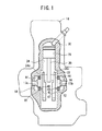
図1及び図2に示すように、解析対象となる転がり軸受10及び12は、単気筒型のエンジン14におけるクランクシャフト16の両端のジャーナル部17a、17bを回転可能に軸支しており、クランクケース18に固定されている。クランクシャフト16はジャーナル部17a及び17bと、コネクティングロッド20の下端部を回転可能に軸支するクランクピン22と、該クランクピン22の両端を支えるとともにバランサとして作用するウェブ24a、24bとを有する。クランクピン22はジャーナル部17a、17bに対して偏心しており、クランクシャフト16が回転することによりコネクティングロッド20の上端に軸支されたピストン26がシリンダボア28内で昇降する。シリンダボア28の上部の燃焼室内には霧化燃料が供給され、点火プラグ30によって着火、爆発してピストン26を所定タイミングで押し下げてクランクシャフト16を回転させることになる。クランクシャフト16には図示しないクラッチ及び変速機を介して車輪が接続されており、自動二輪車等の車両を駆動することができる。霧化燃料の着火、爆発によりクランクシャフト16には変動荷重が加わる。
As shown in FIGS. 1 and 2, the
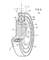
図3に示すように、転がり軸受10は内輪40と、外輪42と、これらの内輪40と外輪42の間に転がり可能に設けられた複数のボール(転動体)44とを有する。ボール44の個数を個数Nとする。外輪42は前記クランクケース18に固定されており、内輪40はジャーナル部17aに接続されている。
As shown in FIG. 3, the rolling
転がり軸受12は転がり軸受10と同構造であり、ジャーナル部17bを軸支している。
The rolling
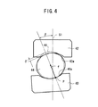
図4に示すように、ボール44は内輪40の軌道面40aと接触点Pで接触し、該接触点Pから接触荷重fを受ける。接触荷重fはラジアル平面(中心軸Zに垂直な平面)S1に対して接触角βの角度の方向に作用する。ボール44は、接触荷重fが作用する方向に貫通量δだけ弾性変形してつぶれている。つまり、ボール44は、軌道面40aと軌道面42aに挟まれることにより微少量だけ潰れて接触面が存在することになり、潰れる以前のボール44の元の形状の外周と軌道面42aとの距離が貫通量δとして定義される。なお、図4においては、理解を容易にするために貫通量δが軌道面42aの側にのみ存在するように図示しているが、実際にはボール44は軌道面40a側も変形しており、軌道面40a側と軌道面42a側はそれぞれδ/2ずつ弾性変形している。
As shown in FIG. 4, the
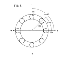
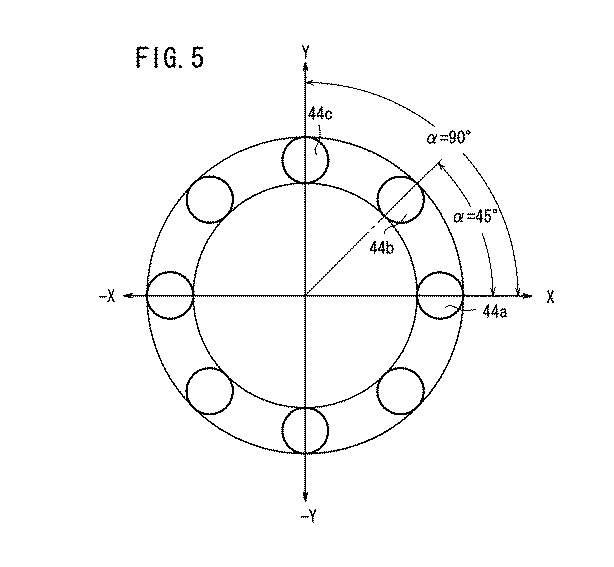
ボール44は転がり軸受10の中心軸Zを基準とした公転角度αに応じて、位置が特定される。つまり、中心軸Zに直交するX軸、Y軸を図5に示すように規定し、ボール44が8つである場合には、X軸上のボール44aは、α=0°又はα=360°として特定される。また、ボール44から反時計方向に順に隣接するボール44b,44cは、それぞれα=45°、α=90°として特定される。また、X−Y平面はラジアル平面S1になる。
The position of the
次に、転がり軸受10及び12を解析するための解析システム50について説明する。
Next, an
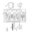
図6に示すように、解析システム50は入力装置としてのキーボード52、マウス54及び記憶媒体ドライブ56と、解析装置としての本体58と、出力装置としてのモニタ60及びプリンタ62とを有する。記憶媒体ドライブ56は出力装置としても用いることができる。解析システム50は、例えば、パーソナルコンピュータシステムを用いることができる。
As shown in FIG. 6, the
本体58は、転がり軸受10、12及びクランクシャフト16等の解析モデルデータD3を作成する転がり軸受特性作成部66と、作成された解析モデルデータD3に基づく解析を行う主計算部68とを有する。
The
転がり軸受特性作成部66は、プリプロセッサ部70と、線形静解析部72と、コンタクトプロセッサ部74とを有する。プリプロセッサ部70は、入力装置から入力された転がり軸受10、12及びクランクシャフト16等の形状、材質等のデータに基づいて線形静解析に必要な内輪40、外輪42及びボール44の有限要素法データD1を作成する部分である。この有限要素法データD1には形状メッシュ、荷重及び所定の境界条件が付加される。線形静解析部72はプリプロセッサ部70で作成された有限要素法データD1を用いて線形静解析を行う部分であり、所定の節点剛性データD2を作成する。この線形静解析部72で行う線形静解析には、汎用構造解析プログラムが利用可能である。
The rolling bearing
コンタクトプロセッサ部74は、線形静解析部72で作成された節点剛性データD2を用いて、内輪40、外輪42及びボール44の接触解析を行い解析モデルデータD3を作成する部分である。コンタクトプロセッサ部74は、ボール44の仮想断面S2上における接触荷重fを求めるための接触関数を作成する手段を有し、該接触関数を解析モデルデータD3に含める。接触関数では貫通量δ、接触角β等パラメータに基づき各ボール44毎の接触荷重fを求めることができる。
The
この解析モデルデータD3は主計算部68に供給されるとともに所定の記憶部に記録される。
The analysis model data D3 is supplied to the
主計算部68は汎用機構解析プログラム80と、該汎用機構解析プログラム80に組み込む解析ソルバ82とを有する。解析ソルバ82は、汎用機構解析プログラム80に組み込まれることにより該汎用機構解析プログラム80と協動的に解析処理を行うことができる。
The
解析ソルバ82は、先ず、クランクケース18の外輪42の取付中心部を基準として内輪40の変位、角度、速度及び角速度を計算する。
The
次に、解析モデルデータD3の接触関数から各ボール44毎の接触荷重fi(i=1〜N)と、減衰とを求め、これらを合成して合成荷重ベクトルF及び合成トルクベクトルTを求める。添え字iは各ボール44の識別番号である。合成荷重ベクトルF及び合成トルクベクトルTは3次元的なベクトルとして求められる。接触荷重fiは仮想断面S2における2次元的なベクトル量として求められ、各ボール44毎にf1、f2、f3…fNとして表される。
Next, the contact load f i (i = 1 to N) for each
解析ソルバ82は、具体的には、次の(1)式及び(2)式に基づいて合成荷重ベクトルF及び合成トルクベクトルTを求める。
Specifically, the
ここで、Fi及びTiはボール44の1個分の接触荷重ベクトル及び軸周りトルクベクトルであり、C( )は減衰を求める関数であり、viは並進速度ベクトルである。C( )は、例えば、接触荷重fiに対する比例関係の関数でもよい。
Here, F i and T i are a contact load vector and a torque vector around the axis of one
またliは中心軸Zから接触点Pまでの距離ベクトルである。func(δi、βi)は、転がり軸受特性作成部66で得られた接触関数であり、fi=func(δi、βi)である。なお、δi及びβiは代表的な引数であり、接触関数はこれ以外の引数をとりうる。
L i is a distance vector from the central axis Z to the contact point P. func (δ i , β i ) is a contact function obtained by the rolling bearing
また、δiは各ボール44毎の貫通量δであり、並進軸方向成分の値として直交する3軸方向の成分値で表される。
Further, δ i is the penetration amount δ for each
さらに、転がり軸受10に加えられる変動荷重等の外力により変位、内輪40及び外輪42の中心位置から転がり軸受10に発生する力及びトルクを求め、これらの力及びトルクを合成荷重ベクトルF及び合成トルクベクトルTに反映させる。
Further, the displacement and the force and torque generated in the rolling
なお、接触荷重fiは、仮想断面S2における2次元的なベクトル量であるが、各ボール44毎に仮想断面S2の向きが異なることから、結局、接触荷重fiは(1)式において3次元的なベクトルとして扱われる。
The contact load f i is a two-dimensional vector quantity in the virtual cross section S2, but since the orientation of the virtual cross section S2 is different for each
求められた合成荷重ベクトルFは、直交するX軸、Y軸及びZ軸の3方向成分に分解され、合成トルクベクトルTは、直交する3つの方向成分(いわゆる、ロール、ピッチ及びヨーの方向成分)に分解され、結局、6軸周りの荷重が求められる。得られた6軸周りの荷重は汎用機構解析プログラム80の解析に供される。これにより、汎用機構解析プログラム80では転がり軸受10、12及びクランクシャフト16の所定の箇所における変位を求めることができる。解析ソルバ82は、汎用機構解析プログラム80における時間領域での数値積分法を用いた計算に対応可能な程度に高速な処理が可能である。
The obtained combined load vector F is decomposed into three directional components of the orthogonal X axis, Y axis and Z axis, and the combined torque vector T is divided into three orthogonal directional components (so-called roll, pitch and yaw directional components). After all, a load around 6 axes is obtained. The obtained loads around the six axes are used for analysis by the general-purpose
次に、このように構成される解析システム50を用いて転がり軸受10、12及びクランクシャフト16の挙動解析を行う方法について説明する。以下の説明では、断りのない限り表記したステップ番号順に処理が実行されるものとする。
Next, a method for analyzing the behavior of the rolling
先ず、図7のステップS1において、入力装置から転がり軸受10、12及びクランクシャフト16等の形状、材質等のデータを入力する。
First, in step S1 of FIG. 7, data such as the shape and material of the rolling
ステップS2において、転がり軸受特性作成部66のプリプロセッサ部70、線形静解析部72及びコンタクトプロセッサ部74が順に動作し、有限要素法データD1、節点剛性データD2及び解析モデルデータD3を作成する。
In step S2, the
このとき、コンタクトプロセッサ部74は、接触関数func(δi、βi)を作成する。
At this time, the
ステップS3において、主計算部68は、クランクケース18の外輪42の取付中心部を基準として内輪40の変位、角度、速度及び角速度を計算する。
In step S <b> 3, the
ステップS4において、ボール44のうち1つを以下のステップS5〜S7の処理対象として特定する。具体的には、所定のカウンタの番号に従い、前記添え字iの番号を特定すればよい。
In step S4, one of the
ステップS5において、添え字iにより特定されるボール44の公転角度αから接触荷重fiが作用するアキシャル平面である仮想断面S2を特定する。
In step S5, a virtual cross section S2 that is an axial plane on which the contact load f i acts is specified from the revolution angle α of the
ステップS6において、前記ステップS5で特定された仮想断面S2内での接触角β及び接触荷重fiを求める。接触荷重fiは前記接触関数func(δi、βi)により求められる。 In step S6, the contact angle β and the contact load f i in the virtual cross section S2 specified in step S5 are obtained. The contact load f i is obtained from the contact function func (δ i , β i ).
ステップS7において、接触荷重fiに基づいて減衰を求める。この減衰は、前記関数C( )により求められる。 In step S7, attenuation is obtained based on the contact load f i . This attenuation is obtained by the function C ().
ステップS8において、全てのボール44について前記ステップS5〜S7の処理を行ったか否かを確認する。全てのボール44について処理が終了していればステップS9へ移り、未終了であればステップS4へ戻る。
In step S8, it is confirmed whether or not the processing in steps S5 to S7 has been performed for all the
ステップS9において、前記(1)式及び(2)式に基づいて合成荷重ベクトルF及び合成トルクベクトルTを求める。 In step S9, a combined load vector F and a combined torque vector T are obtained based on the expressions (1) and (2).
ステップS10において、合成荷重ベクトルF及び合成トルクベクトルTを分解して、6軸周りの荷重を求める。 In step S10, the combined load vector F and the combined torque vector T are decomposed to determine loads around six axes.
ステップS11において、前記ステップS10で求められた6軸周りの荷重を汎用機構解析プログラム80に供給し、有限要素法等の手法により転がり軸受10、12又はクランクシャフト16の所定の箇所における変位を求めることができる。
In step S11, the loads around the six axes obtained in step S10 are supplied to the general-purpose
次に、解析システム50を用いて行われた転がり軸受10、12及びクランクシャフト16の挙動解析の結果について説明する。
Next, the result of behavior analysis of the rolling
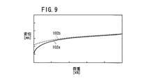
先ず、転がり軸受10及び12の単体の静的剛性検証を行った。つまり、解析モデルデータD3を用いて転がり軸受10及び12に対して静的にラジアル荷重Fr(図3参照)を加えた際のラジアル方向の弾性変形量とラジアル隙間との和である変位量drとラジアル荷重Frとの関係を調べた。同様に、静的にアキシャル荷重Fa(図3参照)を加えた際のアキシャル方向の弾性変形量とアキシャル隙間との和である変位量daとアキシャル荷重Faとの関係を調べた。
First, static rigidity verification of the single bodies of the rolling
図8及び図9に示すように、隙間量dr、daに関して、解析モデルデータD3に基づく解析グラフ線100a及び102aと、予め検証されている基礎グラフ線100b及び102bとはそれぞれ高い相関を示し、解析モデルデータD3を用いた転がり軸受10及び12の静的な剛性を充分再現可能であることが検証された。また、この検証は、ボール44の公転位置のレイアウトが異なる複数の場合について行い、それぞれ高い相関があることが確認された。
As shown in FIGS. 8 and 9, the
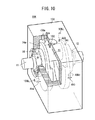
次に、転がり軸受10、12とクランクシャフト16とのアセンブリ状態について検証した。この検証のために、図10に示すアセンブリ検証治具104を用いて実測データを計測した、アセンブリ検証治具104は、実際の転がり軸受10、12及びクランクシャフト16を前記クランクケース18と同様に保持するものであり、クランクピン22には、荷重を加えることのできるボルト106が設けられている。ボルト106は、所定の荷重で破断するように設定されており、該ボルト106が破断するまでの間は静的荷重が加えられ、破断時には衝撃荷重が加えられることになる。
Next, the assembly state of the rolling
アセンブリ検証治具104には、4つのギャップセンサ108a〜108dが設けられており、ウェブ24aの軸方向の変位dxa、上方向の変位dya、ウェブ24bの軸方向の変位dxb、上方向の変位dybが計測可能である。
The
ボルト106が破断するまでの間におけるボルト106に加わる荷重Fsに対する変位dxaを図11に示す。図11から、アセンブリ検証治具104のギャップセンサ108aから得られた実測データ110bと、解析モデルデータD3を用いて解析システム50で得られたシミュレーションデータ110aとは高い相関を示すことが了解される。
FIG. 11 shows the displacement dxa with respect to the load Fs applied to the
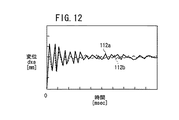
また、ボルト106の破断時における衝撃荷重に対する変位dxaの変化及び変位dyaの変化を図12及び図13に示す。図12から、実測データ112bと、解析モデルデータD3を用いて解析システム50で得られたシミュレーションデータ112aとは高い相関を示すことが了解される。同様に、図13から、実測データ114bと、シミュレーションデータ114aとは高い相関を示すことが了解される。なお、図示を省略するが、変位dxb及び変位dybについても、実測データとシミュレーションデータは高い相関を示した。
Further, FIG. 12 and FIG. 13 show the change of the displacement dxa and the change of the displacement dya with respect to the impact load when the
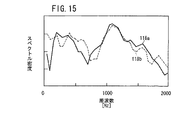
図12及び図13に示す時系列変位結果を用いて、周波数解析を行った結果を図14及び図15に示す。この図14及び図15から了解されるように、特に1000[Hz]前後において実測データ117b及び118bとシミュレーション結果117a及び118aがほぼ符合している。
The results of frequency analysis using the time-series displacement results shown in FIGS. 12 and 13 are shown in FIGS. As understood from FIGS. 14 and 15, the measured
このように、解析モデルデータD3は、静的及び動的な解析に充分適用可能であることが確認された。 Thus, it was confirmed that the analysis model data D3 is sufficiently applicable to static and dynamic analysis.
次に、実際のエンジン14(図1参照)における転がり軸受10、12及びクランクシャフト16の挙動と、解析システム50における解析結果との比較検証を行った。この比較検証のため、実際のエンジン14のクランクケース18にギャップセンサを設けてウェブ24aの変位yを計測するとともに、クランクピン22の隅部の遅角側に歪みゲージを設けて霧化燃料を爆発させる際の歪みsを計測した。エンジン14は、実際に霧化燃料を供給して着火、爆発させて運転した。
Next, the verification of the behavior of the rolling
図16及び図17に示すように、エンジン回転数Neが4000[r/min]時及び8000[r/min]時のクランク角θに対するウェブ24aの変位yは、実測データ120b及び122bとシミュレーションデータ120a及び120aでそれぞれほぼ符合した。
As shown in FIGS. 16 and 17, the displacement y of the
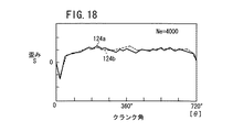
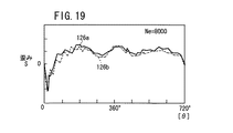
また、図18及び図19に示すように、エンジン回転数Neが4000[r/min]時及び8000[r/min]時のクランク角θに対するクランクピン22の隅部における歪みsは、実測データ124b及び126bとシミュレーションデータ124a及び126aでそれぞれほぼ符合した。
As shown in FIGS. 18 and 19, the distortion s at the corner of the
このように、解析システム50によれば、エンジン14の低速回転域及び高速回転域において実測データと高い相関を示すシミュレーションデータが得られ、実用上充分な解析精度を有することが確認された。
As described above, according to the
また、エンジン回転数Neが10000[r/min]時の歪みsに関して、従来のばね・ダンパモデルを用いた場合のデータは、実測データ又は解析システム50により得られるシミュレーションデータと比較して30%程度の誤差があることが確認され、従来手法と比較して解析システム50の解析精度が高いことが実証された。
Further, regarding the strain s when the engine speed Ne is 10,000 [r / min], the data when the conventional spring / damper model is used is 30% compared with the actual measurement data or the simulation data obtained by the
上述したように、本実施の形態に係る転がり軸受の解析方法及び解析システム50によれば、各ボール44の仮想断面S2上における接触荷重fiを合成して合成荷重ベクトルF及び合成トルクベクトルTを求めることにより、クランクシャフト16が結合されて変動負荷を受ける状態における転がり軸受10、12の剛性を再現可能であって、挙動を解析することができ、しかも充分な解析精度を有する。
As described above, according to the rolling bearing analysis method and
また、実際のエンジン14を運転する際には、ボール44は3次元的で複雑な接触に基づいて公転運動するが、上記の方法によりボール44の運動を仮想断面S2上における運動に置き換えることができ、接触荷重fの数値精度を維持したまま簡便に解析することができる。
Further, when the
さらに、主計算部68では、主に仮想断面S2上の接触荷重fに基づいて解析を行うことから、解析モデルデータD3は構築が容易であり、しかもデータ量や計算負荷が低減し、解析時間の大幅な低減が図られる。
Furthermore, since the
また、本実施の形態に係る転がり軸受の解析方法及び解析システム50は、深溝型の転がり軸受10及び12に限らず、例えば、ころ軸受、ニードル軸受等の各種軸受けに適用可能であることはもちろんである。
Further, the rolling bearing analysis method and the
本発明に係る転がり軸受の解析方法及び解析システムは、上述の実施の形態に限らず、本発明の要旨を逸脱することなく、種々のステップ及び構成を採り得ることはもちろんである。 The rolling bearing analysis method and analysis system according to the present invention are not limited to the above-described embodiments, and various steps and configurations can be adopted without departing from the gist of the present invention.
10、12…転がり軸受 14…エンジン
16…クランクシャフト 17a、17b…ジャーナル部
18…クランクケース 20…コネクティングロッド
22…クランクピン 24a、24b…ウェブ
40…内輪 40a、42a…軌道面
42…外輪 44…ボール
50…解析システム 58…本体
66…転がり軸受特性作成部 68…主計算部
70…プリプロセッサ部 72…線形静解析部
74…コンタクトプロセッサ部 80…汎用機構解析プログラム
82…解析ソルバ
f、fi…接触荷重 func…接触関数
D1…有限要素法データ D2…節点剛性データ
D3…解析モデルデータ F…合成荷重ベクトル
P…接触点 T…合成トルクベクトル
α…公転角度 β、βi…接触角
δ、δi…貫通量
DESCRIPTION OF
Claims (5)
前記各転動体の仮想断面上における接触荷重を求める工程と、
前記各接触荷重を合成して合成荷重ベクトル及び合成トルクベクトルを求める工程と、
を有することを特徴とする転がり軸受の解析方法。 In a method of analyzing a rolling bearing having a substantially coaxial inner ring and outer ring, and a plurality of rolling elements provided between the inner ring and the outer ring so as to allow rolling,
Obtaining a contact load on a virtual cross section of each rolling element;
Combining the contact loads to determine a combined load vector and a combined torque vector;
A rolling bearing analysis method characterized by comprising:
前記仮想断面は、前記転動体が前記内輪又は前記外輪と接触する接触点を含むアキシャル平面であることを特徴とする転がり軸受の解析方法。 In the analysis method of the rolling bearing of Claim 1,
The method of analyzing a rolling bearing, wherein the virtual cross section is an axial plane including a contact point where the rolling element contacts the inner ring or the outer ring.
前記接触荷重は関数で求められ、該関数は解析プログラムにソルバとして組み込まれることを特徴とする転がり軸受の解析方法。 In the analysis method of the rolling bearing of Claim 1,
The contact load is obtained as a function, and the function is incorporated as a solver in an analysis program.
前記転がり軸受の弾性的な特性を含む有限要素法モデルに対して前記合成荷重ベクトル及び前記合成トルクベクトルを作用させ、前記転がり軸受又は該転がり軸受に軸支されるシャフトの所定の箇所における変位又は歪みを求めることを特徴とする転がり軸受の解析方法。 In the analysis method of the rolling bearing of Claim 1,
The combined load vector and the combined torque vector are applied to a finite element method model including elastic characteristics of the rolling bearing, and a displacement or a predetermined position of the rolling bearing or a shaft supported by the rolling bearing is A rolling bearing analysis method characterized by obtaining a strain.
前記各転動体のアキシャル平面上における接触荷重を求める手段と、
前記各接触荷重を合成して合成荷重ベクトル及び合成トルクベクトルを求める手段と、
を有し、
前記アキシャル平面は、前記転動体が前記内輪又は前記外輪と接触する接触点を含む平面であることを特徴とする転がり軸受の解析システム。
In an analysis system for a rolling bearing having a substantially coaxial inner ring and outer ring, and a plurality of rolling elements provided between the inner ring and the outer ring so as to allow rolling,
Means for obtaining a contact load on an axial plane of each rolling element;
Means for combining the contact loads to determine a combined load vector and a combined torque vector;
Have
2. The rolling bearing analysis system according to claim 1, wherein the axial plane is a plane including a contact point where the rolling element contacts the inner ring or the outer ring.
Priority Applications (1)
| Application Number | Priority Date | Filing Date | Title |
|---|---|---|---|
| JP2004106881A JP4723202B2 (en) | 2004-03-31 | 2004-03-31 | Displacement analysis method and displacement analysis system for rolling bearing |
Applications Claiming Priority (1)
| Application Number | Priority Date | Filing Date | Title |
|---|---|---|---|
| JP2004106881A JP4723202B2 (en) | 2004-03-31 | 2004-03-31 | Displacement analysis method and displacement analysis system for rolling bearing |
Publications (2)
| Publication Number | Publication Date |
|---|---|
| JP2005291356A true JP2005291356A (en) | 2005-10-20 |
| JP4723202B2 JP4723202B2 (en) | 2011-07-13 |
Family
ID=35324515
Family Applications (1)
| Application Number | Title | Priority Date | Filing Date |
|---|---|---|---|
| JP2004106881A Expired - Lifetime JP4723202B2 (en) | 2004-03-31 | 2004-03-31 | Displacement analysis method and displacement analysis system for rolling bearing |
Country Status (1)
| Country | Link |
|---|---|
| JP (1) | JP4723202B2 (en) |
Cited By (7)
| Publication number | Priority date | Publication date | Assignee | Title |
|---|---|---|---|---|
| JP2007298458A (en) * | 2006-05-02 | 2007-11-15 | Ntn Corp | Dynamic analysis method of rolling bearing under planetary motion |
| JP2008116040A (en) * | 2006-10-13 | 2008-05-22 | Ntn Corp | Cage stress analysis method and stress analysis system |
| JP2009533615A (en) * | 2006-04-11 | 2009-09-17 | エーツェーツェーインジェニーア エクスペルテンチームズ ゲーエムベーハー イー.ゲー. | Reciprocating piston engine |
| JP2010152653A (en) * | 2008-12-25 | 2010-07-08 | Jtekt Corp | Method for analyzing rigidity in structure body |
| CN109027017A (en) * | 2018-08-15 | 2018-12-18 | 重庆交通大学 | A kind of Space Rolling Bearing state of wear appraisal procedure |
| CN110516290A (en) * | 2019-07-12 | 2019-11-29 | 徐州美驰车桥有限公司 | The finite element method of one bulb pivoting support |
| CN111209705A (en) * | 2020-01-15 | 2020-05-29 | 同济大学 | Finite element-based three-dimensional flexible assembly tolerance prediction method for glass lifter |
Families Citing this family (1)
| Publication number | Priority date | Publication date | Assignee | Title |
|---|---|---|---|---|
| US11573154B2 (en) | 2019-12-13 | 2023-02-07 | Caterpillar Inc. | System and method for estimating ring-related parameters |
Citations (1)
| Publication number | Priority date | Publication date | Assignee | Title |
|---|---|---|---|---|
| WO2003087745A2 (en) * | 2002-04-11 | 2003-10-23 | Fag Kugelfischer Ag & Co. Kg | Roller bearings equipped with sensors |
-
2004
- 2004-03-31 JP JP2004106881A patent/JP4723202B2/en not_active Expired - Lifetime
Patent Citations (1)
| Publication number | Priority date | Publication date | Assignee | Title |
|---|---|---|---|---|
| WO2003087745A2 (en) * | 2002-04-11 | 2003-10-23 | Fag Kugelfischer Ag & Co. Kg | Roller bearings equipped with sensors |
Cited By (10)
| Publication number | Priority date | Publication date | Assignee | Title |
|---|---|---|---|---|
| JP2009533615A (en) * | 2006-04-11 | 2009-09-17 | エーツェーツェーインジェニーア エクスペルテンチームズ ゲーエムベーハー イー.ゲー. | Reciprocating piston engine |
| JP2007298458A (en) * | 2006-05-02 | 2007-11-15 | Ntn Corp | Dynamic analysis method of rolling bearing under planetary motion |
| JP2008116040A (en) * | 2006-10-13 | 2008-05-22 | Ntn Corp | Cage stress analysis method and stress analysis system |
| JP2010152653A (en) * | 2008-12-25 | 2010-07-08 | Jtekt Corp | Method for analyzing rigidity in structure body |
| CN109027017A (en) * | 2018-08-15 | 2018-12-18 | 重庆交通大学 | A kind of Space Rolling Bearing state of wear appraisal procedure |
| CN109027017B (en) * | 2018-08-15 | 2019-12-10 | 重庆交通大学 | A method for evaluating the wear state of space rolling bearings |
| CN110516290A (en) * | 2019-07-12 | 2019-11-29 | 徐州美驰车桥有限公司 | The finite element method of one bulb pivoting support |
| CN110516290B (en) * | 2019-07-12 | 2022-10-21 | 徐州美驰车桥有限公司 | Finite element analysis method of ball slewing bearing |
| CN111209705A (en) * | 2020-01-15 | 2020-05-29 | 同济大学 | Finite element-based three-dimensional flexible assembly tolerance prediction method for glass lifter |
| CN111209705B (en) * | 2020-01-15 | 2024-04-26 | 同济大学 | Three-dimensional flexible assembly tolerance prediction method for glass lifter based on finite element |
Also Published As
| Publication number | Publication date |
|---|---|
| JP4723202B2 (en) | 2011-07-13 |
Similar Documents
| Publication | Publication Date | Title |
|---|---|---|
| Xu et al. | Modeling and analysis of planar multibody systems containing deep groove ball bearing with clearance | |
| Montazersadgh et al. | Dynamic load and stress analysis of a crankshaft | |
| Flores et al. | Numerical and experimental investigation on multibody systems with revolute clearance joints | |
| Dubowsky et al. | An experimental and analytical study of impact forces in elastic mechanical systems with clearances | |
| Erkaya | Effects of balancing and link flexibility on dynamics of a planar mechanism having joint clearance | |
| Sun et al. | Dynamic analysis of the variable stiffness support rotor system with elastic rings | |
| Xu et al. | An approach for calculating the dynamic load of deep groove ball bearing joints in planar multibody systems | |
| Liu et al. | Establishment of dynamic model for axle box bearing of high-speed trains under variable speed conditions | |
| Liu et al. | Investigation on characteristics of vibration interaction between supporting bearings in rotor-bearing system | |
| JP4723202B2 (en) | Displacement analysis method and displacement analysis system for rolling bearing | |
| He et al. | Dynamic analysis of rolling bearings with roller spalling defects based on explicit finite element method and experiment | |
| Ba et al. | Analysis of piston-pin lubrication considering the effects of structure deformation and cavitation | |
| Shi et al. | Dynamic modeling considering time-varying contact pairs and parameterized defects of deep groove ball bearings for its vibration characteristic analysis | |
| Yuan et al. | Analysis of dynamic characteristics of gas turbine rotor considering contact effects and pre-tightening force | |
| Xu | A general method for impact dynamic analysis of a planar multi-body system with a rolling ball bearing joint | |
| Chen et al. | Clearance-induced contact trajectory uncertainty of angular contact ball bearing under coupling operating condition | |
| Bellakhdhar et al. | A simplified coupled crankshaft–engine block model | |
| Wang et al. | Study on torsional vibration response of compressor flexible rotor system considering collision clearance | |
| Wang et al. | Lubrication analysis of a connecting-rod bearing in a high-speed engine. Part I: rod and bearing deformation | |
| Ganguly et al. | Balancing optimization of a motorcycle engine crankshaft for vibration reduction | |
| Kim et al. | Excitation force analysis of a powertrain based on CAE technology | |
| Szumiński | Determination of the stiffness of rolling kinematic pairs of manipulators | |
| Siano et al. | Simulation of a multi-cylinder engine vibrational behaviour | |
| Duran et al. | Dynamic simulation and endurance limit safety factor calculation for crankshaft-comparison of single mass and dual mass flywheel | |
| Pan et al. | Unified model of rub-impact vibration response of high-low pressure double-rotor-SFD-intermediate bearing system of aero-engine under typical maneuvering loads |
Legal Events
| Date | Code | Title | Description |
|---|---|---|---|
| A621 | Written request for application examination |
Free format text: JAPANESE INTERMEDIATE CODE: A621 Effective date: 20061129 |
|
| A131 | Notification of reasons for refusal |
Free format text: JAPANESE INTERMEDIATE CODE: A131 Effective date: 20090901 |
|
| A521 | Request for written amendment filed |
Free format text: JAPANESE INTERMEDIATE CODE: A523 Effective date: 20091030 |
|
| A131 | Notification of reasons for refusal |
Free format text: JAPANESE INTERMEDIATE CODE: A131 Effective date: 20100330 |
|
| A521 | Request for written amendment filed |
Free format text: JAPANESE INTERMEDIATE CODE: A523 Effective date: 20100430 |
|
| A02 | Decision of refusal |
Free format text: JAPANESE INTERMEDIATE CODE: A02 Effective date: 20101005 |
|
| A521 | Request for written amendment filed |
Free format text: JAPANESE INTERMEDIATE CODE: A523 Effective date: 20110105 |
|
| A911 | Transfer to examiner for re-examination before appeal (zenchi) |
Free format text: JAPANESE INTERMEDIATE CODE: A911 Effective date: 20110111 |
|
| TRDD | Decision of grant or rejection written | ||
| A01 | Written decision to grant a patent or to grant a registration (utility model) |
Free format text: JAPANESE INTERMEDIATE CODE: A01 Effective date: 20110329 |
|
| A01 | Written decision to grant a patent or to grant a registration (utility model) |
Free format text: JAPANESE INTERMEDIATE CODE: A01 |
|
| A61 | First payment of annual fees (during grant procedure) |
Free format text: JAPANESE INTERMEDIATE CODE: A61 Effective date: 20110407 |
|
| FPAY | Renewal fee payment (event date is renewal date of database) |
Free format text: PAYMENT UNTIL: 20140415 Year of fee payment: 3 |
|
| R150 | Certificate of patent or registration of utility model |
Free format text: JAPANESE INTERMEDIATE CODE: R150 |