JP2005291460A - Position adjusting method and device of work roller - Google Patents
Position adjusting method and device of work roller Download PDFInfo
- Publication number
- JP2005291460A JP2005291460A JP2004111136A JP2004111136A JP2005291460A JP 2005291460 A JP2005291460 A JP 2005291460A JP 2004111136 A JP2004111136 A JP 2004111136A JP 2004111136 A JP2004111136 A JP 2004111136A JP 2005291460 A JP2005291460 A JP 2005291460A
- Authority
- JP
- Japan
- Prior art keywords
- work
- work roll
- roll
- bearing block
- holding member
- Prior art date
- Legal status (The legal status is an assumption and is not a legal conclusion. Google has not performed a legal analysis and makes no representation as to the accuracy of the status listed.)
- Pending
Links
- 238000000034 method Methods 0.000 title claims description 15
- 238000006073 displacement reaction Methods 0.000 claims abstract description 48
- 230000002093 peripheral effect Effects 0.000 claims abstract description 7
- 238000004080 punching Methods 0.000 description 17
- 238000007639 printing Methods 0.000 description 8
- 238000005520 cutting process Methods 0.000 description 6
- 239000002131 composite material Substances 0.000 description 2
- 238000003754 machining Methods 0.000 description 2
- 238000003825 pressing Methods 0.000 description 2
- 101100465000 Mus musculus Prag1 gene Proteins 0.000 description 1
- 230000015572 biosynthetic process Effects 0.000 description 1
- 230000003247 decreasing effect Effects 0.000 description 1
- 230000000694 effects Effects 0.000 description 1
- 238000005516 engineering process Methods 0.000 description 1
- 238000005530 etching Methods 0.000 description 1
- 239000011888 foil Substances 0.000 description 1
- 239000000463 material Substances 0.000 description 1
- 239000002184 metal Substances 0.000 description 1
- 238000007645 offset printing Methods 0.000 description 1
- 230000001105 regulatory effect Effects 0.000 description 1
- 230000000452 restraining effect Effects 0.000 description 1
- 238000004804 winding Methods 0.000 description 1
Images


Landscapes
- Advancing Webs (AREA)
- Rolls And Other Rotary Bodies (AREA)
Abstract
Description
この発明は、連続的または間欠的に走行変位される、プラスチック、紙、金属箔、複合紙等の、フィルム状部材をも含むシート状ワークに、印刷、型抜き、裁断、厚みの中間位置までハーフカット等を施すに当って、たとえば、相互に対向して対をなし、ともに回転駆動される支持ロールと作業ロールとを具える作業ステーションの複数段にわたって、互いに関連する一連の加工を行う場合等の、それぞれの作業ステーションの相互間での、シート状ワークに対する加工位置の位置ずれを修正するに用いて好適な作業ロールの位置調整方法および、その方法の実施に用いる位置調整装置に関するものであり、とくには、作業ロールに取付けた被動側の歯車の、駆動側部材との連結状態はそのままに、作業ロール、ひいては、そこに設けた作業手段の円周方向位置を、簡単かつ容易に、しかも、正確に調整する技術を提案するものである。 The present invention can be applied to a sheet-like workpiece including a film-like member such as plastic, paper, metal foil, composite paper, etc., which is continuously or intermittently displaced, up to an intermediate position of printing, die cutting, cutting, and thickness. When performing half-cutting, for example, when performing a series of processing related to each other across multiple stages of a work station that includes a support roll and a work roll that are rotationally driven together and are opposed to each other. The present invention relates to a position adjustment method of a work roll suitable for correcting a positional deviation of a processing position with respect to a sheet-like workpiece between the respective work stations, and a position adjustment apparatus used for carrying out the method. Yes, in particular, the work roll, and therefore the work provided there, while the connected state of the driven gear attached to the work roll to the drive side member remains unchanged The circumferential position of the stage, simply and easily, moreover, is to propose a precise adjustment technique.
シート状ワークを、たとえば、輪転印刷用の刷版、上記ハーフカットのための打抜刃その他の作業手段を設けた作業ロールと、それと対をなす支持ロールとを具える作業ステーションの複数段にわたって走行させて、対をなす両ロールの協働下で、シート状ワークに多色刷り印刷、同芯状その他をなす複数種類の重ね合わせハーフカット等の加工を施す場合は、相互に隣接する作業ステーションのそれぞれでの加工が互いに関連性をもつことになるので、たとえば、前段側の作業ステーションと後段側の作業ステーションとの間で、作業手段の、ロール円周方向での相対的な位置ずれが生じたときは、印刷ずれ、カットずれ等が発生することになる。 The sheet-like work is spread over a plurality of stages of a work station including, for example, a printing plate for rotary printing, a work roll provided with a punching blade for other half-cutting and other work means, and a support roll that is paired with the work roll. Work stations that are adjacent to each other when multiple sheets of multi-color printing, concentric shapes, etc., are performed under the cooperation of both rolls that run and work in pairs Therefore, for example, the relative displacement of the working means in the circumferential direction of the roll between the work station on the front stage and the work station on the rear stage is, for example, related to each other. When this occurs, a print misalignment, a cut misalignment, or the like occurs.
これがため、作業手段、直接的にはそれを設けた作業ロールの相対的な位置ずれの発生に対しては、少なくとも一本の作業ロールの、円周方向位置を調整してその位置ずれを取り除くことが必要になる。 For this reason, with respect to the occurrence of relative displacement of the work means, directly the work roll provided with the work means, the circumferential position of at least one work roll is adjusted to remove the displacement. It will be necessary.
そこで従来は、図7に例示するように、大径の支持ロール111と、それより小径の作業ロール112とを具える作業ステーションStにおいて、それらの両ロール111、112を、それぞれの歯車114と115との噛合によって駆動連結するとともに、支持ロール111を駆動側に連結した構成とした場合に、作業ロール112の円周方向位置の調整を可能とするべく、たとえば、作業ロール112の胴部端面にボルト116によって締付け固定した歯車115と支持ロール歯車114との噛合状態を保ったままで、そのボルト116を緩めて、作業ロール112への歯車115の緊締を解除して、作業ロール112をボルト116とともに、歯車115に設けた、図7(b)に斜視図で示すような弧状穴117の形成範囲内で、歯車115に対して相対回動可能とすることが提案されている。
Therefore, conventionally, as illustrated in FIG. 7, in a work station St including a large-
しかるに、この従来技術による、作業ロールの位置調整は、ボルト116を緩めて、歯車115による拘束を解かれた作業ロール112を、作業者の手作業によって回動変位させることにより行なわれることになるので、位置調整作業の煩わしさが否めず、しかも、微少にして正確な調整のためには、繰返しの、または、比較的長い時間をかけた調整が必要になるという問題があった。
However, the position adjustment of the work roll according to this prior art is performed by loosening the
この発明は、提案技術が抱えるこのような問題点を解決することを課題としてなされたものであり、それの目的とするところは、作業ロールの位置調整を簡易・迅速に、しかも常に正確に行なうことができる作業ロールの位置調整方法および、その方法の実施に用いる位置調整装置を提供するにある。 The present invention has been made to solve such problems of the proposed technology, and the object of the present invention is to easily and quickly adjust the position of the work roll, and always accurately. An object of the present invention is to provide a work roll position adjustment method that can be used, and a position adjustment device that is used to implement the method.
この発明に係る、作業ロールの位置調整方法は、相互に対向して対をなす、駆動側部材に歯車を介して連結される作業ロールと、支持ロールとを具える作業ステーションの複数段にシート状ワークを順次に通過させて、そのワークに所定の加工を施すに当り、前段側作業ステーションの作業ロールと、後段側作業ステーションの作業ロールとの相対位置の修正を、作業ロールの中心軸の両端を軸受け支持するそれぞれの軸受けブロックを支持ロールへの接線の方向へ、歯車の回動変位を伴って平行変位させて、作業ロールの周面を支持ロールに対して相対回動させることによって行うにある。 According to the present invention, there is provided a work roll position adjustment method comprising: a work roll connected to a drive side member via a gear; and a support roll; When the workpieces are sequentially passed through and the workpiece is subjected to the predetermined machining, the relative position between the work roll of the front work station and the work roll of the rear work station is corrected with the central axis of the work roll. Each bearing block that supports both ends of the bearing is displaced in parallel with the rotational displacement of the gear in the direction of the tangent to the support roll, and the peripheral surface of the work roll is rotated relative to the support roll. It is in.
ここで、各軸受けブロックの前記平行変位は、そのブロックを両側部から挟み込む一対の挟持部材のうち、一方側の挟持部材の軸受けブロック当接面をそのブロックに対して進退変位させるとともに、他方側の挟持部材をその進退変位に追従させて変位させることによって行うことが好ましい。 Here, the parallel displacement of each bearing block causes the bearing block contact surface of one clamping member of the pair of clamping members that sandwich the block from both sides to move forward and backward with respect to the block, and the other side. It is preferable to carry out by displacing the holding member by following the forward / backward displacement.
また好ましくは、一方側の挟持部材の軸受けブロック当接面の進退変位を、その挟持部材の、支持ロール表面に対する、カム面に沿わせた接近離隔変位に基いて行わせる。 Further, preferably, the forward / backward displacement of the bearing block contact surface of the holding member on one side is performed based on the approaching / separating displacement of the holding member along the cam surface with respect to the surface of the support roll.
この一方で、他方側の挟持部材の前記追従変位は、その挟持部材の、一方側挟持部材の軸受けブロック当接面の進退変位方向への移動または、その進退変位方向と直交する、支持ロール表面に対する接近離隔移動によって行わせることが好ましい。 On the other hand, the follow-up displacement of the holding member on the other side is the movement of the holding member in the forward / backward displacement direction of the bearing block contact surface of the one-side holding member, or the support roll surface orthogonal to the forward / backward displacement direction. It is preferable that the movement is performed by approaching and moving away from.
また、この発明に係る、作業ロールの位置調整装置は、駆動側の歯車と常時噛合される被動側歯車を設けた、支持ロールと対をなす作業ロールの両端を、たとえば直方体もしくは立方体形状をなすそれぞれの軸受ブロックで支持するとともに、各軸受けブロックを、支持フレームに形成した切欠き内で、対をなす挟持部材によって両側部から挟持し、いずれか一方側の挟持部材を、傾斜カム面を形成する切欠き縁面への接触下で、作業ロールと対向する支持ロールの周面に接近および離隔する方向に変位可能とするとともに、この変位に基いて、その挟持部材、ひいては、それの軸受けブロック当接面を、軸受けブロックの一方の側面、たとえば、作業ロールと支持ロールとのそれぞれの中心軸線を通る平面と平行となる垂直もしくは水平側面に対して進退変位可能とし、そして、他方側の挟持部材を、ばね手段の付勢下で、軸受けブロックの他方の側面に常時押圧し、さらに、一方側の挟持部材に一端部を掛合させた揺動レバーを挟持フレームに取付けたものである。 Further, the work roll position adjusting device according to the present invention is provided with a driven side gear that is always meshed with the drive side gear, and the work roll paired with the support roll has, for example, a rectangular parallelepiped shape or a cubic shape. Each bearing block is supported by each bearing block, and each bearing block is clamped from both sides by a pair of clamping members in a notch formed in the support frame, and either side clamping member forms an inclined cam surface It is possible to displace in the direction approaching and separating from the peripheral surface of the support roll opposite to the work roll under the contact with the notched edge surface, and based on this displacement, the clamping member, and consequently the bearing block thereof The contact surface is one side of the bearing block, for example, the vertical or horizontal side parallel to the plane passing through the central axis of each of the work roll and the support roll. The holding member on the other side is always pressed against the other side surface of the bearing block under the bias of the spring means, and one end portion is engaged with the holding member on the one side. The swing lever is attached to the holding frame.
ここで、他方側の挟持部材は、ばね手段による付勢方向との関連の下で、たとえば、垂直姿勢となる、軸受けブロックの他方の側面と直交する方向、いいかえれば、一方側挟持部材の進退方向に移動可能とする他、その進退方向と直交する方向に移動可能とすることもできる。 Here, the holding member on the other side is, for example, in a direction perpendicular to the other side surface of the bearing block in a vertical posture in relation to the biasing direction by the spring means, in other words, the forward and backward movement of the one side holding member. In addition to being movable in the direction, it is also possible to be movable in a direction orthogonal to the forward / backward direction.
かかる装置において好ましくは、揺動レバーの他端部に当接してそれの揺動姿勢を特定するねじ手段を支持フレームに設ける。そしてまた好ましくは、それぞれの軸受けブロックのためのそれぞれの揺動レバーを、一本の軸部材上に固定する。なおこの場合には、上記ねじ手段を、いずれか一方の揺動レバーと対応する一個所だけに配設することができる。 In such an apparatus, preferably, the support frame is provided with screw means for abutting against the other end of the swing lever and specifying the swing posture thereof. Also preferably, each swing lever for each bearing block is fixed on one shaft member. In this case, the screw means can be disposed only at one position corresponding to one of the swing levers.
この発明の位置調整方法では、作業ロールの両端を軸受け支持するそれぞれの軸受けブロックを、作業ロールに固定した歯車の回動変位を伴って、支持ロールへの接線の延在方向、たとえば水平方向に平行変位させ、これに基いて、作業ロールの周面、ひいては、そこに設けた刷版、打抜刃等とすることができる作業手段を、それがより速いタイミングで機能する進み方向またはより遅いタイミングで機能することになる遅れ方向に、所要に応じて相対回動させることにより、作業ロールの位置調整を、調整量の多少にかかわらず、常に正確に、しかも簡易・迅速に行なうことができる。 In the position adjusting method of the present invention, each bearing block that supports both ends of the work roll is supported in the extending direction of the tangent to the support roll, for example, in the horizontal direction, with the rotational displacement of the gear fixed to the work roll. Based on this, the working means, which can be the peripheral surface of the work roll, and hence the printing plate, punching blade, etc. provided there, is advanced in the direction in which it functions at a faster timing or slower. By rotating relative to the delay direction that will function at the timing as required, the position of the work roll can be adjusted accurately, easily and quickly regardless of the amount of adjustment. .
ところで、この場合の各軸受けブロックの平行変位を、そのブロックを挟み込む一方側の挟持部材の、たとえば垂直面となるブロック接触面の進退変位と、これを原因とする、他方側の挟持部材の追従変位とによって行わせるときは、一方側の挟持部材の外部操作だけで、作業ロールの位置調整を、簡単かつ容易に、また、作業者の感、経験等を必要とすることなく、常に高精度に行うことができる。 By the way, the parallel displacement of each bearing block in this case is the following movement of the holding member on the other side caused by the forward and backward displacement of the block contact surface, for example, the vertical surface of the holding member on one side that holds the block. When performing displacement, the position of the work roll can be easily and easily adjusted only by external operation of the holding member on one side, and it is always highly accurate without requiring the operator's feeling or experience. Can be done.
また、一方側の挟持部材の上記の進退変位を、作業ロールと対をなす支持ロールの表面に対する、その挟持部材の、傾斜カム面に沿わせた接近離隔変位に基いて行わせる場合は、カム面の傾斜角度の選択の下で、作業ロールの位置調整を、その調整量が微少であってもより高精度に行うことができる。 When the above-mentioned forward / backward displacement of the holding member on one side is performed based on the approaching / separating displacement of the holding member along the inclined cam surface with respect to the surface of the support roll paired with the work roll, Under the selection of the inclination angle of the surface, the position adjustment of the work roll can be performed with higher accuracy even if the adjustment amount is small.
これに対し、他方側の挟持部材の上記の追従変位を、その挟持部材の、一方側挟持部材の進退方向への移動によって行わせる場合は、その追従変位を十分円滑なものとすることができ、また、他方側の挟持部材の、たとえば傾斜カム面の作用の下での、上記進退方向直交する方向の、たとえば支持ロール表面に対する接近離隔移動によって行わせる場合は、両挟持部材による軸受ブロック挟持力を高めて、作業ロールをより安定的に保持することができる。 On the other hand, in the case where the following displacement of the other side clamping member is performed by the movement of the one side clamping member in the advancing / retreating direction, the following displacement can be made sufficiently smooth. Also, when the holding member on the other side is moved by approaching and moving away from the surface of the support roll, for example, in the direction orthogonal to the advancing and retreating direction under the action of the inclined cam surface, for example, the bearing block is held by both the holding members. The force can be increased and the work roll can be held more stably.
この発明の位置調整装置では、支持フレームに設けた切欠き内で、軸受けブロックをその両側部から挟持する一対の挟持部材のいずれか一方側のものを、傾斜カム面を形成する切欠き縁面への接触下で、支持ロールの周面に接近および離隔する方向に変位させ、これに基いて、その挟持部材の軸受けブロック当接面をその軸受けブロックの一方の側面に対して進退変位させ、そして、この進退変位を原因として、他方側の挟持部材を、ばね手段の作用に基く、軸受けブロックの十分なる挟持下でその変位に追従させることで、作業ロールの位置調整方法について前述したように、軸受けブロックを、歯車の回動変位を伴って平行変位させることができ、この結果として、作業ロール、ひいては、そこに設けた作業手段の位置を、簡易・迅速に、かつ正確に調整することができる。 In the position adjusting device according to the present invention, one of the pair of clamping members that clamp the bearing block from both sides thereof in the notch provided in the support frame is formed as a notched edge surface that forms an inclined cam surface. The contact block is displaced in a direction approaching and separating from the peripheral surface of the support roll under the contact with the base, and based on this, the bearing block contact surface of the clamping member is moved forward and backward with respect to one side surface of the bearing block, Then, due to this forward / backward displacement, the other side clamping member is caused to follow the displacement under the sufficient clamping of the bearing block based on the action of the spring means, as described above for the position adjustment method of the work roll. The bearing block can be displaced in parallel with the rotational displacement of the gears. As a result, the position of the work roll and thus the working means provided there can be easily and quickly And it can be accurately adjusted.
なおこの場合は、一方側の挟持部材はカム従節としても機能することになるので、それの、切欠き傾斜カム面との対向面には、そのカム面と対応する傾斜面を設ける一方で、軸受けブロックとの対抗面は、ブロック側面に面接触する、傾斜のない平坦面、たとえば垂直面とする。 In this case, since the clamping member on one side also functions as a cam follower, an inclined surface corresponding to the cam surface is provided on the surface facing the notched inclined cam surface. The opposing surface to the bearing block is a flat surface that is in contact with the side surface of the block and has no inclination, for example, a vertical surface.
このような一方側の挟持部材は、たとえば、横断面形状をほぼコ字状として、切欠きの内側から外側に向いて支持フレームの傾斜カム面を挟む姿勢として切欠き内に配置することができ、かかる、配置姿勢は、他方側の挟持部材についてもほぼ同様とすることができる。 Such a holding member on one side can be arranged in the notch so as to sandwich the inclined cam surface of the support frame from the inside to the outside of the notch, for example, with a substantially U-shaped cross section. Such an arrangement posture can be made substantially the same for the holding member on the other side.
またここでは、一方側の挟持部材に一端部を掛合させた揺動レバーを支持フレームに対して揺動変位させて、一方側の挟持部材の、支持ロールに対する相対位置を変化させることで、その位置変化を、外部から十分円滑にかつ容易に行わせることができ、また、傾斜カム面の傾斜角度との関連の下で、その挟持部材の軸受けブロック当接面の進退変位量を、高い精度を持って簡単に特定することができる。 Also, here, by swinging and displacing a swinging lever having one end engaged with the holding member on one side with respect to the support frame, and changing the relative position of the holding member on one side with respect to the support roll, The position can be changed smoothly and easily from the outside, and the amount of advancement and retraction of the bearing block abutment surface of the clamping member is highly accurate in relation to the inclination angle of the inclined cam surface. Can be easily identified.
以上のような装置において、他方側の挟持部材は、ばね手段による付勢の下で、軸受けブロックの他の側面、たとえば重直面と直交する方向または、その他方の側面に沿う方向に移動可能としたときは、その挟持部材を、先に述べたように、一方側挟持部材の進退方向または、支持ロール表面に接近しもしくは離隔する方向に追従変位させることができる。 In the apparatus as described above, the holding member on the other side is movable under the biasing force of the spring means in the other side of the bearing block, for example, the direction perpendicular to the heavy face or the direction along the other side. In this case, as described above, the holding member can be displaced to follow in the advancing / retreating direction of the one-side holding member or the direction approaching or separating from the support roll surface.
なお、他方側挟持部材を、軸受けブロックの他方の側面に沿う方向に移動可能とする後者にあっては、その挟持部材を、たとえば軸受けブロックの中心軸線方向に追従変位させることも可能となる。 In the latter case in which the other side clamping member is movable in the direction along the other side surface of the bearing block, the clamping member can be displaced following, for example, in the direction of the central axis of the bearing block.
そしてまた、揺動レバーの他端部に当接してそれの揺動姿勢を特定するねじ手段を設けた場合には、たとえば雄ねじ部材のねじ込み量の微妙な調節により、カム面の作用とも相俟って、作業ロール位置の微調整をより容易に行うことができる。 In addition, in the case where screw means for contacting the other end portion of the swing lever and specifying the swing posture thereof is provided, for example, by adjusting the screwing amount of the male screw member, the effect of the cam surface is compatible. Thus, fine adjustment of the work roll position can be performed more easily.
ところで、それぞれの軸受けブロックのためのそれぞれの揺動レバーを、一本の共通の軸部材上に固定したときは、その軸部材を回動させることで、両揺動レバーを同期作動させて、それぞれの軸受けブロックを同時に、ともに等しい量だけ平行移動させることができる。 By the way, when each rocking lever for each bearing block is fixed on one common shaft member, both the rocking levers are operated synchronously by rotating the shaft member, Each bearing block can be translated by the same amount at the same time.
従って、一方の揺動レバーに関連させて、上記の一のねじ手段を設けた場合には、そのねじ手段の操作によって双方の揺動レバーを作動させることが可能となり、装置の構造を簡単にするとともに、装置を小型化することができる。 Therefore, when the one screw means is provided in relation to one of the swing levers, both the swing levers can be operated by operating the screw means, and the structure of the apparatus can be simplified. In addition, the apparatus can be miniaturized.
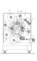
図1は、この発明に係る位置調整装置を適用した作業装置を、支持ローラ、作業ローラ等の手前側の支持フレームを取り外して示す正面図であり、図2は、その作業装置の要部拡大斜視図である。 FIG. 1 is a front view showing a working apparatus to which the position adjusting device according to the present invention is applied, with a support frame on the front side such as a supporting roller and a working roller removed, and FIG. 2 is an enlarged view of a main part of the working apparatus. It is a perspective view.
図1に示すところにおいて、1は作業装置の駆動系を収納するハウジングを示し、2a、2b、2c、2dは、そのハウジング1に突設されて、たとえば、テープ状の形態をなすシート状ワークの巻回ロールからの、そのシート状ワークの繰出軸を、そして3a、3b、3cは、これもハウジングに突設されて、たとえば、打抜刃によってハーフカットされた複合紙の不要部分を巻き取る巻取軸をそれぞれ示し、また4は、シート状ワークに所要の加工を施した後の製品巻取軸を示す。
In FIG. 1, reference numeral 1 denotes a housing that houses a drive system of a working device, and
ここでは、ハウジング1の中央部分に、一本の共通の支持ロール5を突設するとともに、この支持ロール5の周りに、複数、図では六本のニップロール6を周方向に間隔をおいて配設し、そして、これらのニップロール間に、支持ロール5と対向してそれと対をなす、図では三本の作業ロール7a、7b、7cをハウジング1に突設させて設ける。
Here, a
ここで、ニップロール6は、巻回ロールから連続的または間欠的に繰出されたシート状ワークを支持ロール5に押圧するべく機能し、また、作業ロール7a、7b、7cはいずれも、たとえば、マグネットロール8に、作業手段の一例としての、フレキシブルエッチング刃からなる打抜刃9を磁気吸着させてなり、各作業ロール7a、7b、7cは、一本の共通の支持ロール5との協働下で、シート状ワークにハーフカットを施すべく機能する。
Here, the
これがため、図1および図2に示すところでは、一本の支持ロール5の周りに90°の間隔をおいて配設した三本のそれぞれの作業ロール7a、7b、7cと、共通の一本の支持ロール5とは三個所で対をなして三段の作業ステーションS1、S2、S3を構成する。
For this reason, as shown in FIG. 1 and FIG. 2, each of the three work rolls 7 a, 7 b, 7 c disposed at a 90 ° interval around one
かかる構成によれば、それぞれの作業ステーションに各1本の支持ロールを設けて、それらの作業ステーションを相互に並列配置するタンデムタイプ作業装置に比して、構造を簡単にするとともに、装置全体を小型化することができる。
なお、図では打抜刃9としてなる作業手段を、たとえば、オフセット印刷等の刷版その他とすることも可能であり、また、作業ステーションの数は、図に示すところに比して適宜に増減することもできる。
According to such a configuration, each work station is provided with one support roll, and the structure is simplified as compared with a tandem type work apparatus in which the work stations are arranged in parallel with each other. It can be downsized.
In the figure, the working means serving as the
ところで、図示の作業装置において、たとえば、一本の繰出軸2aから繰出したシート状ワークWに、三段のそれぞれの作業ステーションS1,S2,S3のそれぞれの作業ロール7a,7b,7cをもって、相互に関連する打抜き加工を順次に施すに当って、仮りに、ステーションS2の作業ロール7b、ひいては、そこに設けた打抜刃9に、他の作業ロール7a,7cの打抜刃9に対する相対的な位相遅れまたは進みが生じた場合には、それを修正して、所期した通りの、三段にわたる適正な加工を可能とすることが必要になり、このような現象は、他の作業ロール7a,7cについても同様に発生することが考えられる。
By the way, in the illustrated working apparatus, for example, the sheet-like workpiece W fed from one
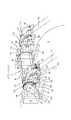
そこでここでは、両端を軸受けブロック10を介して前後の支持フレーム11に支持される少なくとも一本の作業ロール7a、7b、7c(以下「作業ロール7」で代表する)について、図3に図1の要図拡大図で、そして、図4に斜視図で示すように、作業ロール7の中心軸12の一方の端部分上に、駆動側の歯車13に常時噛合される歯車14を、それのボス部15を介してねじ止め固定した状態の下で、各軸受けブロック10を、支持フレーム11に設けた、支持ロール5の半径方向に延びる切欠き16内で、対をなす挟持部材17、18によってそれの両側部から十分大きな力で挟持して支持する。
Therefore, here, at least one
なおここにおいては、挟持部材17、18をともに横断面形状がほぼコ字状をなすものとし、このような挟持部材17、18を、切欠き16の内側から外側に向けて支持フレーム11を間に挟む態様として配設しているが、たとえば、それらの横断面形状を鉤形状とし、鉤部分の内面が、切欠き16の縁面に接触する態様としてそれらの挟持部材17、18を切欠き16内に配設することもできる。
In this case, both of the holding
そして、図に示すところでは、切欠き16の、図の右側となる一方の縁面を、図3に示すところから明らかなように、切欠き16の開口側に向けて切欠き幅を次第に挟める向きに直線状に傾斜する傾斜カム面19とするとともに、この傾斜カム面19を跨ぐ一方側の挟持部材17の、そのカム面19との対抗面を、それと同方向へ同角度で傾斜してカム面19に面接触する直線状傾斜面20として、この挟持部材17を、支持ロール5の表面から離隔する方向および近接する方向のそれぞれへ、カム面19に対して相対変位させることで、そのカム面19と直線状傾斜面20との接触下で、挟持部材17、ひいては、それの、軸受けブロック10の、図では重直面とした一方の側面に面接触する当接面21を、そのブロック側面に対する進出方向および後退方向の両方向に変位可能とする。
As shown in FIG. 3, as shown in FIG. 3, the width of the
一方、切欠き16内の他方側の挟持部材18は、上述した切欠きカム面19とは反対の側で、これも図では重直面とした切欠き縁面22、すなわち、作業ロール7の中心軸線と支持ロール5の中心軸線とを含む平面と平行となる切欠き縁面を跨いだ姿勢として配置して、この挟持部材18を、たとえば、一端を、切欠き16の縁面22に設けた窪みの底壁に、そして他端を、その挟持部材18の、これも重直面とした、切欠き縁面22との対向面に設けた窪みの底壁にそれぞれ着座させたばね手段23によって軸受けブロック10側へ常時付勢する。これにより、挟持部材18の、軸受けブロック10の他方の重直面に面接触する当接面24は、そのブロック10を、一方側の挟持部材17に向けて大きな力で押圧して、両挟持部材17、18による軸受けブロック10の挟持を実現する。
On the other hand, the holding
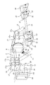
さらにここでは、一方側の挟持部材17の、支持ロール5に対する前述したような離隔および近接変位の、円滑にして容易な外部操作を可能とするべく、たとえば、図5に、図4の分解斜視図で示すところから明らかなように、一方側の各挟持部材17の、支持フレーム11を挟むそれぞれのフランジ部分17aに、それのブロック当接面21と直交する方向に長く延材させて形成した切欠き部25を設ける一方で、中間部を、支持フレーム11で揺動自在に支持した、図ではその支持フレーム11を隔てて対をなす揺動レバー26の先端を、それらに共通の一本のピン27を介して切欠き部25内へ嵌込み、支持フレーム11に、かかるピン27の円弧運動を許容する弧状穴28を設ける。
Further, here, for example, FIG. 5 is an exploded perspective view of FIG. 4 in order to enable smooth and easy external operation of the holding
このような構成によれば、揺動レバー26を揺動させて、その先端の掛合ピン27を切欠き部25内で変位させることで、一方側の挟持部材17をカム面19に沿わせて、図の上下方向に変位させることができ、これにより、その挟持部材17を、軸受けブロック10とともに、他方側挟持部材18の方向、すなわち、支持ロール5への接線の方向に進出変位させることができ、また、他方側の挟持部材18を、それを付勢するばね手段23のばね力に抗して軸受けブロック10とともに後退変位させることができる。
According to such a configuration, the oscillating
なお図に示すところでは、切欠き16のカム面19を、切欠き開口に向けて切欠き幅を次第に狭める向きの傾斜面としているも、その傾斜面の傾き方向をそれとは逆向きとすることもでき、この場合には、揺動レバー26の変位に伴う、一方側の挟持部材17の変位方向を、上記の場合とは逆方向とすることができる。
In the figure, the
ところで、揺動レバー26の所要の揺動変位は、たとえば図3に示すように、支持フレーム11に固定したブラケット29に、紙面に直交する方向に偏らせて螺合されて、対をなす一方の揺動レバー26の、支点に対してピン27とは反対側の表面に直接的に当接する調整ねじ30のねじ込み量を調節することで、その変位量の多少にかかわらず、所期した通りに正確に行わせることができ、好ましくは、そのねじ込み量を、ロックナック31をもって特定することで、揺動レバー26を、所要の位置に確実に保持することができる。
By the way, the required swing displacement of the
また、対をなす揺動レバー26の双方の、より直接的な揺動変位は、たとえば図4および図5に示すように、支持フレーム11に螺合させた調整ねじ32を、両揺動レバー26の相互の連結をもたらす連結ロッド33に当接させることによって行わせることができ、この場合は、調整ねじ32の操作によって、揺動レバー対を直接的にともに等しい量だけ揺動させることができる。
Further, as shown in FIGS. 4 and 5, for example, as shown in FIG. 4 and FIG. 5, the
ここで、対をなす揺動レバー26のそれぞれは、たとえば、支持フレーム11に回動自在に支持した枢軸34、または、支持フレーム11に固定した軸の周りに回動自体に取付けた筒状の枢軸上に、その支持フレーム11を隔てて嵌め合わせるとともに、各レバー26に形成されて、枢軸34への嵌め合わせ穴に達するスリット35の幅をボルト36によって締め込んで、両レバー26をともに等しい姿勢でその枢軸34に強固に固定することにより、支持フレーム11に揺動自在に支持することができる。
Here, each of the pair of swing levers 26 is, for example, a
そしてこの場合は、図4、5に示すように、一本の枢軸34を二枚の支持フレーム11に支持される。それぞれの対の揺動レバー26に共用して、いずれか一の揺動レバー26を揺動させることで、全ての揺動レバー26の、同時にして同量の揺動変位を可能にしたときは、調整ねじ30、32をいずれか一方の支持フレーム11だけに配設することで、一方側の挟持部材17のそれぞれに所要の変位を行わせることができる。
In this case, as shown in FIGS. 4 and 5, one
なお、図4、5に示すところでは、一の挟持部材17に二本の揺動レバー26を掛合させることとしているも、図1〜3に例示するように、一の挟持部材17当り一本の揺動レバーだけを、たとえば支持フレーム11の内側に配設し得ることはもちろんであり、この場合にもまた、それぞれの揺動レバーを一本の共通の枢軸34上に固定することができる。
4 and 5, two
また、図示はしないが、たとえば枢軸上に配設したひげばね、コイルばね等のばね部材によって、揺動レバーを、それが調整ねじ30、32の先端に常時押圧される方向に付勢して、調整ねじ30、32を緩める場合の、揺動レバーの復帰変位をより確実にすること、調整ねじ30、32の先端を揺動レバーに直接的もしくは間接的に螺合させて、調整ねじの、そのレバーへの螺合量に応じて揺動レバーを確実に変位させること等もできる。 Although not shown, for example, a spring member such as a beard spring or a coil spring disposed on the pivot is used to urge the swing lever in a direction in which it is always pressed against the tips of the adjustment screws 30 and 32. When the adjustment screws 30 and 32 are loosened, the return displacement of the rocking lever is made more reliable, and the tips of the adjustment screws 30 and 32 are screwed directly or indirectly into the rocking lever to The rocking lever can be surely displaced according to the screwing amount to the lever.
以上のように構成してなる作業ロールの変位調整装置によって、たとえば、図1に示す、作業ステーションS2の作業ロール7の位置を、作業ステーションS1の作業ロール7に対して調整する場合は、作業ステーションS2での、作業ロール7のセットねじ40を緩めて、その作業ロール7の、切欠き16の幅方向での変位を可能とした状態で、調整ねじ30、32を締め込んで、または緩めて揺動レバー26を変位させ、これに基いて、一方側の挟持部材17を、切欠きカム面19に沿わせて図の上方側もしくは下方側へ変位させる。
For example, when the position of the
挟持部材17のこの変位は、それの直線状傾斜面20の、カム面19に対する摺接運動下にて行われ、この結果として、狭持部材17は、軸受けブロック10に対して進出する方向もしくは後退する方向への水平変位を行うことになる。
This displacement of the pinching
ここで、挟持部材17が進出変位する場合についてみると、軸受けブロック10は、その一方側の挟持部材17の押圧力により、他方側の挟持部材18を、ばね手段23の押圧力に抗して後退変位させながら水平変位する。この場合、作業ロール7の歯車14は、駆動側の歯車13との常時の噛合状態にあるので、軸受けブロック10のこのような水平変位は、歯車13の、駆動側歯車13に対する、たとえば正転方向への回転変位および、作業ロールそれ自体の正転方向の回動変位を伴って行われることになり、これがため、作業ロール7の、作業手段としての打抜刃9は、挟持部材17の進出変位位置に応じた角度範囲にわたって、進み方向に回動変位されることになる。
Here, as for the case where the clamping
したがって、作業ステーションS2での打抜き加工位置が作業ステーションS1での加工位置に対して遅れ側、たとえば、シート状ワークの走行方向前方側に偏って位置することになる場合には、一方側の挟持部材17を進出変位させることでその偏りを、簡単かつ容易に、しかも正確に取り除くことができる。
Therefore, when the punching processing position at the work station S2 is located behind the processing position at the work station S1, for example, on the front side in the traveling direction of the sheet-like workpiece, it is clamped on one side. By moving the
この一方で、挟持部材17を後退変位させた場合には、軸受けブロック10は、ばね手段23の作用の下で、他方側の挟持部材18とともに、一方側の挟持部材17の方向に水平変位され、これにより、歯車13および作業ロール7は逆転方向に回動変位されることになる。従がってここでは、打抜刃9は遅れ方向に回動変位されることになり、その作業ロール7による打抜き加工位置が、シート状ワークの走行方向後方側に相対的に偏った場合の作業ロール位置の、適正位置への調整が行われることになる。
On the other hand, when the holding
このようにして作業ロール7の位置調整を終えた後は、セットねじ40を締め込んで、その作業ロール7を作動位置に拘束することで、シート状ワークに対する打抜き加工を再開することができる。
After finishing the position adjustment of the
以上、作業ステーションS2の作業ロール7の位置調整を行う場合について説明したが、このことは、作業ステーションS1、S3の少なくとも一方に先に述べた位置調整装置を設けることで、それらの作業ステーションにおいても同様にして行うことができる。
The case where the position of the
図6は、この発明に係る装置の他の実施形態を示す要部拡大図である。
ここでは、支持フレーム11に設けた切欠き16の、他方側の挟持部材18が跨ぐ縁面をもまた、挟持部材17が跨ぐ傾斜カム19とほぼ平行に延在する傾斜カム面41とするとともに、その他方側の挟持部材18に、その傾斜カム面41に面接触する直線状傾斜面42を設け、また、その挟持部材18をばね部材43によって、図では下方側となる支持ロール5側へ付勢し、併せて、その挟持部材18の位置を雄ねじ部材44をもって規制しており、この点において前記装置とは構成を異にするものである。
FIG. 6 is an enlarged view of a main part showing another embodiment of the apparatus according to the present invention.
Here, the
これがためここでは、雄ねじ部材44を緩めた状態で、一方側の挟持部材17を軸受けブロック10に対して進出変位させて、その軸受けブロック10を他方側の挟持部材18に押圧することで、その挟持部材18は、カム面41の作用下で、ばね部材43のばね力に抗して図の上方側へ逃げ変位することになり、その結果として、軸受けブロック10の、他方側の挟持部材18の方向への図では水平変位が行われることになる。
なおここでの、挟持部材18の、支持ロール5から離隔する方向の、上方側への逃げ変位は、カム面41の勾配を小さくするほど、小さな力の作用下で円滑に行われることになる。
For this reason, in this state, with the
Here, the upward displacement of the clamping
これに対し、一方側の挟持部材17を後退変位させたときは、軸受けブロック10は、ばね部材43によって図の下方側に変位される挟持部材18に押圧されて、その一方側の挟持部材17の方向に水平変位されることになる。
On the other hand, when the holding
そして、軸受けブロック10の、このようないずれの方向の変位に当っても、歯車14および作業ロール7は軸受けブロック10の変位方向および変位量に応じて回動されることになるので、作業ロール7の打抜刃9もまた同様に変位されることになる。
Even if the
このようにして作業ロール7の位置調整を終えた後は、雄ねじ部材44を締め込んで挟持部材18の位置を特定し、また、セットねじ40を締め込んで作業ロール7を作動位置に拘束することで作業を再開することができる。
After finishing the position adjustment of the
ところで、図6中の45は、一方側の挟持部材17に、カム面19の傾き方向に、それと平行に延在させて設けた長孔を、そして46は、支持フレーム11に突設されてその長孔45に嵌まり込むピンをそれぞれ示し、これらの両者は、相互の協働下で、挟持部材17の円滑なる変位を案内するべく機能する。
Incidentally, 45 in FIG. 6 is provided with a long hole provided in the holding
以上作業ロールに、作業手段としての打抜刃を設ける場合について説明したが、作業手段を輪転印刷の刷版とすることもでき、作業ロールそれ自体を印刷用の版胴とすることもできる。
また作業手段を、シート状ワークを完全に打抜く型抜刃、裁断刃等とすることもできる。
In the above description, the work roll is provided with a punching blade as a work means. However, the work means can be a rotary printing plate, and the work roll itself can be a printing plate cylinder.
Further, the working means may be a die cutting blade, a cutting blade or the like for completely punching a sheet-like workpiece.
5 支持ロール
7,7a,7b,7c 作業ロール
8 マグネットロール
9 打抜刃
10 軸受けブロック
11 支持フレーム
12 中心軸
13 駆動側歯車
14 歯車
15 ボス部
16 切欠き
17,18 挟持部材
17a フランジ部分
19,41 傾斜カム面
20,42 直線状傾斜面
21,24 当接面
22 切欠き縁面
23 ばね手段
25 切欠き部
26 揺動レバー
27 ピン
28 弧状穴
29 ブラケット
30,32 調整ねじ
33 連結ロッド
34 枢軸
35 スリット
36 ボルト
40 セットねじ
43 ばね部材
44 雄ねじ部材
45 長孔
46 ピン
W シート状ワーク
S1,S2,S3 作業ステーション
DESCRIPTION OF
Claims (8)
前段側作業ステーションの作業ロールと、後段側作業ステーションの作業ロールとの相対位置の修正を、作業ロールの中心軸の両端を軸受け支持するそれぞれの軸受けブロックを、支持ロールへの接線の方向へ、歯車の回動変位を伴って平行変位させて、作業ロールの周面を支持ロールに対して相対回動させることにより行う作業ロールの位置調整方法。 A sheet-like workpiece is sequentially passed through a plurality of stages of a work station including a work roll connected to a drive side member via a gear and a support roll, which are opposed to each other, and a support roll. In performing the processing of
Correction of the relative position between the work roll of the front work station and the work roll of the rear work station, and the respective bearing blocks that support both ends of the central axis of the work roll in the direction of the tangent to the support roll, A method for adjusting the position of a work roll, wherein the work roll is displaced in parallel with the rotational displacement of the gear and the peripheral surface of the work roll is rotated relative to the support roll.
The position adjusting device of the work roll according to any one of claims 5 to 7, wherein each swing lever for each bearing block is fixed on one shaft member.
Priority Applications (1)
| Application Number | Priority Date | Filing Date | Title |
|---|---|---|---|
| JP2004111136A JP2005291460A (en) | 2004-04-05 | 2004-04-05 | Position adjusting method and device of work roller |
Applications Claiming Priority (1)
| Application Number | Priority Date | Filing Date | Title |
|---|---|---|---|
| JP2004111136A JP2005291460A (en) | 2004-04-05 | 2004-04-05 | Position adjusting method and device of work roller |
Publications (1)
| Publication Number | Publication Date |
|---|---|
| JP2005291460A true JP2005291460A (en) | 2005-10-20 |
Family
ID=35324605
Family Applications (1)
| Application Number | Title | Priority Date | Filing Date |
|---|---|---|---|
| JP2004111136A Pending JP2005291460A (en) | 2004-04-05 | 2004-04-05 | Position adjusting method and device of work roller |
Country Status (1)
| Country | Link |
|---|---|
| JP (1) | JP2005291460A (en) |
-
2004
- 2004-04-05 JP JP2004111136A patent/JP2005291460A/en active Pending
Similar Documents
| Publication | Publication Date | Title |
|---|---|---|
| US5001950A (en) | Rotary die cutter | |
| KR101008589B1 (en) | Plate feeder | |
| JP2001018191A (en) | Rotatable knife roller | |
| JPH08504682A (en) | Rotating device with movable die | |
| KR20150132729A (en) | Flexible workpiece clamping device of punching machine for flexible workpiece | |
| JPH08323684A (en) | Equipment for cutting whole paper | |
| JP2016168653A (en) | Tube cutting apparatus | |
| JP2005291460A (en) | Position adjusting method and device of work roller | |
| JP2008279569A (en) | Slitter blade positioning device | |
| JPH09136758A (en) | Adjusting mechanism of crosswise prick punch machine | |
| CN210236658U (en) | Strip dividing device of printing machine | |
| CA1333255C (en) | Rotary die cutter | |
| JP4328199B2 (en) | Rotating cutter device and method for adjusting fixed blade mounting angle in rotating cutter device | |
| JP3993575B2 (en) | Work roll position adjusting method and apparatus | |
| JP2020114599A (en) | Feed roller moving device | |
| JP4651455B2 (en) | Material feeder | |
| JPH10109217A (en) | Side guide for slitter | |
| JP3556792B2 (en) | Cutting tool mounting structure for rotary die cutter | |
| JP2007125666A (en) | Hoop cutter | |
| JPH01127553A (en) | Conveying device for web at theta | |
| JP3045276U (en) | Sewing machine for sheet ON. OFF unit | |
| JPH0730324Y2 (en) | Ruler positioning device for workbench | |
| EP3676063A1 (en) | A module of a machine with a die cutting function | |
| JP4989060B2 (en) | Cutting device | |
| CN121928124A (en) | Station and method for rotary transverse cutting of materials |
Legal Events
| Date | Code | Title | Description |
|---|---|---|---|
| A621 | Written request for application examination |
Effective date: 20060719 Free format text: JAPANESE INTERMEDIATE CODE: A621 |
|
| A977 | Report on retrieval |
Effective date: 20081112 Free format text: JAPANESE INTERMEDIATE CODE: A971007 |
|
| A131 | Notification of reasons for refusal |
Free format text: JAPANESE INTERMEDIATE CODE: A131 Effective date: 20081209 |
|
| A521 | Written amendment |
Free format text: JAPANESE INTERMEDIATE CODE: A523 Effective date: 20090115 |
|
| RD03 | Notification of appointment of power of attorney |
Effective date: 20090115 Free format text: JAPANESE INTERMEDIATE CODE: A7423 |
|
| A131 | Notification of reasons for refusal |
Effective date: 20090317 Free format text: JAPANESE INTERMEDIATE CODE: A131 |
|
| A02 | Decision of refusal |
Free format text: JAPANESE INTERMEDIATE CODE: A02 Effective date: 20090707 |