JP2005291501A - Rolling bearing unit for wheel support - Google Patents
Rolling bearing unit for wheel support Download PDFInfo
- Publication number
- JP2005291501A JP2005291501A JP2005177772A JP2005177772A JP2005291501A JP 2005291501 A JP2005291501 A JP 2005291501A JP 2005177772 A JP2005177772 A JP 2005177772A JP 2005177772 A JP2005177772 A JP 2005177772A JP 2005291501 A JP2005291501 A JP 2005291501A
- Authority
- JP
- Japan
- Prior art keywords
- inner ring
- shaft member
- ring
- peripheral surface
- caulking
- Prior art date
- Legal status (The legal status is an assumption and is not a legal conclusion. Google has not performed a legal analysis and makes no representation as to the accuracy of the status listed.)
- Granted
Links
Images


Classifications
-
- F—MECHANICAL ENGINEERING; LIGHTING; HEATING; WEAPONS; BLASTING
- F16—ENGINEERING ELEMENTS AND UNITS; GENERAL MEASURES FOR PRODUCING AND MAINTAINING EFFECTIVE FUNCTIONING OF MACHINES OR INSTALLATIONS; THERMAL INSULATION IN GENERAL
- F16C—SHAFTS; FLEXIBLE SHAFTS; ELEMENTS OR CRANKSHAFT MECHANISMS; ROTARY BODIES OTHER THAN GEARING ELEMENTS; BEARINGS
- F16C43/00—Assembling bearings
- F16C43/04—Assembling rolling-contact bearings
-
- F—MECHANICAL ENGINEERING; LIGHTING; HEATING; WEAPONS; BLASTING
- F16—ENGINEERING ELEMENTS AND UNITS; GENERAL MEASURES FOR PRODUCING AND MAINTAINING EFFECTIVE FUNCTIONING OF MACHINES OR INSTALLATIONS; THERMAL INSULATION IN GENERAL
- F16C—SHAFTS; FLEXIBLE SHAFTS; ELEMENTS OR CRANKSHAFT MECHANISMS; ROTARY BODIES OTHER THAN GEARING ELEMENTS; BEARINGS
- F16C19/00—Bearings with rolling contact, for exclusively rotary movement
- F16C19/02—Bearings with rolling contact, for exclusively rotary movement with bearing balls essentially of the same size in one or more circular rows
- F16C19/14—Bearings with rolling contact, for exclusively rotary movement with bearing balls essentially of the same size in one or more circular rows for both radial and axial load
- F16C19/18—Bearings with rolling contact, for exclusively rotary movement with bearing balls essentially of the same size in one or more circular rows for both radial and axial load with two or more rows of balls
- F16C19/181—Bearings with rolling contact, for exclusively rotary movement with bearing balls essentially of the same size in one or more circular rows for both radial and axial load with two or more rows of balls with angular contact
- F16C19/183—Bearings with rolling contact, for exclusively rotary movement with bearing balls essentially of the same size in one or more circular rows for both radial and axial load with two or more rows of balls with angular contact with two rows at opposite angles
- F16C19/184—Bearings with rolling contact, for exclusively rotary movement with bearing balls essentially of the same size in one or more circular rows for both radial and axial load with two or more rows of balls with angular contact with two rows at opposite angles in O-arrangement
- F16C19/186—Bearings with rolling contact, for exclusively rotary movement with bearing balls essentially of the same size in one or more circular rows for both radial and axial load with two or more rows of balls with angular contact with two rows at opposite angles in O-arrangement with three raceways provided integrally on parts other than race rings, e.g. third generation hubs
-
- F—MECHANICAL ENGINEERING; LIGHTING; HEATING; WEAPONS; BLASTING
- F16—ENGINEERING ELEMENTS AND UNITS; GENERAL MEASURES FOR PRODUCING AND MAINTAINING EFFECTIVE FUNCTIONING OF MACHINES OR INSTALLATIONS; THERMAL INSULATION IN GENERAL
- F16C—SHAFTS; FLEXIBLE SHAFTS; ELEMENTS OR CRANKSHAFT MECHANISMS; ROTARY BODIES OTHER THAN GEARING ELEMENTS; BEARINGS
- F16C2326/00—Articles relating to transporting
- F16C2326/01—Parts of vehicles in general
- F16C2326/02—Wheel hubs or castors
Landscapes
- Engineering & Computer Science (AREA)
- General Engineering & Computer Science (AREA)
- Mechanical Engineering (AREA)
- Mounting Of Bearings Or Others (AREA)
- Rolling Contact Bearings (AREA)
Abstract
【課題】 シャフト部材2に対して内輪3を、シャフト部材2の円筒部21をかしめ広げる事により固定するのに、内輪3やかしめ広げ部分を損傷しにくくする。
【解決手段】 内輪3の端部内周面に傾斜面19を形成し、この傾斜面19に向けて、上記円筒部21をかしめ広げる。この円筒部21の変形量が少なく、かしめ広げ部分を損傷しにくくすると共に、上記内輪3の変形量を少なく抑える事もできる。
【選択図】 図1To fix an inner ring 3 to a shaft member 2 by caulking and expanding a cylindrical portion 21 of the shaft member 2, the inner ring 3 and caulking and spreading portions are hardly damaged.
An inclined surface 19 is formed on an inner peripheral surface of an end portion of an inner ring 3, and the cylindrical portion 21 is caulked and spread toward the inclined surface 19. The amount of deformation of the cylindrical portion 21 is small, it is difficult to damage the caulking and spreading portion, and the amount of deformation of the inner ring 3 can be reduced.
[Selection] Figure 1
Description
この発明に係る車輪支持用転がり軸受ユニットは、自動車の車輪を懸架装置に対して回転自在に支持する為に利用する。 The wheel support rolling bearing unit according to the present invention is used for rotatably supporting a wheel of an automobile with respect to a suspension device.
自動車の車輪は、車輪支持用転がり軸受ユニットにより懸架装置に支持する。この様な場合に使用する車輪支持用転がり軸受ユニットとして、従来から例えば、特許文献1〜8等に記載されたものが知られている。又、図8は、従来から広く実施されている車輪支持用転がり軸受ユニットの1例を示している。この車輪支持用転がり軸受ユニット1は、シャフト部材2と、内輪3と、外輪4と、複数個の転動体5、5とを備える。このうちのシャフト部材2の外周面の外端部(外とは、自動車への組み付け状態で幅方向外寄りとなる側を言い、各図の左側となる。反対に幅方向中央寄りとなる側を内と言い、各図の右側となる。)で上記外輪4から突出した部分には、車輪を支持する為の第二のフランジ6を形成している。又、このシャフト部材2の中間部には第一の内輪軌道7を、同じく内端部には外径寸法が小さくなった段部8を、それぞれ形成している。
The wheels of the automobile are supported on the suspension device by a rolling bearing unit for supporting the wheels. As wheel support rolling bearing units used in such a case, those described in, for example, Patent Documents 1 to 8 have been known. FIG. 8 shows an example of a wheel bearing rolling bearing unit that has been widely used in the past. The wheel support rolling bearing unit 1 includes a
そして、この段部8に、その外周面に第二の内輪軌道9を形成した上記内輪3を外嵌している。上記シャフト部材2の内端部には雄ねじ部10を形成し、この雄ねじ部10の先端部を、上記内輪3の内端面よりも内方に突出させている。そして、この雄ねじ部10に螺合したナット11と上記段部8の段差面12との間で上記内輪3を挟持する事により、この内輪3を上記シャフト部材2の所定位置に結合固定している。上記雄ねじ部10の先端部外周面には係止凹部17を形成している。そして、上記ナット11を所定のトルクで緊締した後、このナット11の一部で上記係止凹部17に整合する部分を直径方向内方にかしめ付ける事により、このナット11の緩み止めを図っている。尚、上記シャフト部材2に1対の内輪を外嵌し、これら1対の内輪の外周面に、第一、第二の内輪軌道7、9を設ける構造も、従来から知られている。
And the said inner ring |
又、上記外輪4の内周面には、上記第一の内輪軌道7と対向する第一の外輪軌道13及び上記第二の内輪軌道9に対向する第二の外輪軌道14を形成している。そして、これら第一、第二の内輪軌道7、9と第一、第二の外輪軌道13、14との間に上記転動体5、5を、それぞれ複数個ずつ設けている。これら各転動体5、5の設置空間の外端開口はシールリング22により、内端開口は蓋体29により、それぞれ塞いでいる。尚、図示の例では、転動体5、5として玉を使用しているが、重量の嵩む自動車用の車輪支持用転がり軸受ユニットの場合には、これら転動体としてテーパころを使用する場合もある。
A first
上述の様な車輪支持用転がり軸受ユニット1を自動車に組み付けるには、上記外輪4を、その外周面の一部に形成した第一のフランジ15により懸架装置に固定し、上記第二のフランジ6に車輪を固定する。この結果、この車輪が懸架装置に対して回転自在に支持される。
In order to assemble the wheel-supporting rolling bearing unit 1 as described above to an automobile, the
又、前記特許文献7には、図9に示す様な構造の車輪支持用転がり軸受ユニット1が記載されている。この従来構造の第2例の場合には、シャフト部材2の内端部に形成した円筒部の一部で内輪3の内端面よりも内方に突出した部分を直径方向外方に折り曲げる事により、かしめ部16を形成している。そして、このかしめ部16と段部8の段差面12との間で、上記内輪3を挟持している。
図8に示した従来構造の第1例の場合には、雄ねじ部10の先端部に係止凹部17を形成する作業、及びナット11の一部を直径方向内方にかしめ付ける作業が必要になる。この為、車輪支持用転がり軸受ユニット1の部品製造作業及び組立作業が面倒になり、コストが嵩む。
In the case of the first example of the conventional structure shown in FIG. 8, it is necessary to perform an operation of forming the
又、図9に示した第2例の構造の場合、シャフト部材2に対して内輪3を結合固定する為のかしめ部16の形成時に、このかしめ部16が隣接する内輪3の内周面に、直径方向外方に向いた力が加わる。この為、この内輪3の直径が僅かとは言え変化する。そして、この変化量が大きくなると、この内輪3に亀裂等の損傷が発生する可能性が生じるだけでなく、転動体5、5に付与した予圧を適正値に維持する作業が面倒になり、上記内輪3を含む車輪支持用転がり軸受ユニット1の耐久性を確保する事が難しくなる可能性がある。特に、上記シャフト部材2に対して上記内輪3が回転する事を防止すべく、上記かしめ部16のかしめ強度を十分に確保しようとした場合には、上記変形量が大きくなり易く、上記内輪3の耐久性確保が難しくなる。
Further, in the case of the structure of the second example shown in FIG. 9, when the
この様な事情に鑑みて特願平8−36800号には、内輪の端面とかしめ部との間にスペーサリングを設け、かしめ部の形成作業に伴う、直径方向外方に向いた力をこのスペーサリングにより受ける構造が開示されている。この先発明に係る構造によれば、かしめ部の形成作業に伴って発生する、直径方向外方に向いた力の大部分を上記スペーサリングが受ける。従って、上記内輪にはこの直径方向外方に向いた力が殆ど伝わらず、この内輪の損傷防止を図れる。但し、この様なスペーサリングを設けた構造の場合でも、上記かしめ部自体、円筒部からの加工量が多く、かしめ作業に伴う変形に基づいて亀裂等が発生し易く、耐久性の確保が難しい。 In view of such circumstances, in Japanese Patent Application No. 8-36800, a spacer ring is provided between the end face of the inner ring and the caulking portion, and the force directed outward in the diameter direction due to the caulking portion forming operation is A structure received by a spacer ring is disclosed. According to the structure according to the present invention, the spacer ring receives most of the force directed outward in the diametrical direction that is generated along with the forming operation of the caulking portion. Therefore, almost no force directed outward in the diameter direction is transmitted to the inner ring, and damage to the inner ring can be prevented. However, even in the case of such a structure provided with a spacer ring, the amount of processing from the caulking portion itself and the cylindrical portion is large, and cracks are likely to occur due to deformation accompanying caulking work, and it is difficult to ensure durability. .
本発明の車輪支持用転がり軸受ユニットは、この様な事情に鑑みて、内輪の内径がこの内輪の固定作業に基づいて変化しない様にし、且つかしめ部に亀裂等の損傷が発生しにくくすると共に、シャフト部材に対し内輪を固定するナットの緩み止めを図る為の係止凹部の形成作業やナットのかしめ付け作業を省略する事により、コスト低減を図る事を目的に発明したものである。 In view of such circumstances, the wheel bearing rolling bearing unit of the present invention prevents the inner ring from changing its inner diameter based on the fixing operation of the inner ring, and makes it difficult to cause damage such as cracks in the caulking portion. The invention was invented for the purpose of reducing the cost by omitting the operation of forming the locking recesses and the caulking operation of the nuts for preventing the nuts from being loosened to fix the inner ring to the shaft member.
本発明の車輪支持用転がり軸受ユニットは何れも、従来の、或は先発明の車輪支持用転がり軸受ユニットと同様に、外周面に第一のフランジを、内周面に複列の外輪軌道を、それぞれ設けた外輪と、端部外周面に第二のフランジを設けたシャフト部材と、外周面に内輪軌道を有し上記シャフト部材に外嵌した、少なくとも1個の内輪と、この内輪を含んで上記シャフト部材と共に回転する部分の外周面に設けた第一、第二の内輪軌道と上記複列の外輪軌道との間に、それぞれ複数個ずつ設けた転動体とを備える。そして、上記シャフト部材の端部に形成した円筒部の一部で上記内輪よりも突出した部分を直径方向外方にかしめ広げ、このかしめ広げた部分により上記内輪を直接又はスペーサリングを介して抑え付ける事により、上記内輪を上記シャフト部材に固定している。
特に、本発明の車輪支持用転がり軸受ユニットに於いては、上記内輪若しくはこの内輪よりも上記シャフト部材の先端寄りに外嵌したスペーサリングの開口周縁部で上記円筒部をかしめ広げた部分の外周面が押し付けられる部分を、開口端に向かう程内径が大きくなる、円錐凹面状の傾斜面としている。
Each of the wheel support rolling bearing units of the present invention has a first flange on the outer peripheral surface and a double-row outer ring raceway on the inner peripheral surface, as in the conventional or the wheel support rolling bearing unit of the previous invention. Each including an outer ring, a shaft member provided with a second flange on the outer peripheral surface of the end, at least one inner ring having an inner ring raceway on the outer peripheral surface and externally fitted to the shaft member, and the inner ring And a plurality of rolling elements provided between the first and second inner ring raceways provided on the outer peripheral surface of the portion rotating together with the shaft member, and the double row outer ring raceways. Then, a part of the cylindrical portion formed at the end of the shaft member is caulked outward in the diametrical direction, and the inner ring is suppressed directly or via a spacer ring. By attaching, the inner ring is fixed to the shaft member.
In particular, in the rolling bearing unit for supporting a wheel according to the present invention, the outer periphery of the inner ring or a portion where the cylindrical portion is caulked and widened at the opening peripheral portion of the spacer ring that is fitted closer to the tip of the shaft member than the inner ring. The portion where the surface is pressed is a conical concave inclined surface whose inner diameter increases toward the opening end.
上述の様に構成される本発明の車輪支持用転がり軸受ユニットにより、懸架装置に対して車輪を回転自在に支持する作用は、従来の車輪支持用転がり軸受ユニットと同様である。
特に、本発明の車輪支持用転がり軸受ユニットの場合には、シャフト部材の端部に形成した円筒部をかしめ広げた部分の外周面が押し付けられる部分を、開口端に向かう程内径が大きくなる、円錐凹面状の傾斜面としている為、このかしめ部分の変形量が少なくて済む。この為、このかしめ部分に発生する歪みを小さく抑えて、このかしめ部に割れ等の損傷が発生するのを抑える事ができる。又、上記変形量を少なく抑える為、このかしめ部を形成する事に基づき、上記円筒部の周囲に存在する部材にその直径方向外方に加わる力を低減できる。この結果、スペーサリングを用いた場合は勿論、スペーサリングを用いない場合でも、内輪にその直径方向外方に加わる力を低減して、この内輪の損傷防止を図れる。
本発明の車輪支持用転がり軸受ユニットは、上述の様に構成され作用するので、内輪の直径が変化する事を防止して、この内輪及びこの内輪を固定する為のかしめ広げ部分が、上記内輪の固定作業に基づいて損傷する可能性を低くできる。又、予圧を適正値に維持でき、しかも部品点数、部品加工、組立工数の減少により、コスト低減を図れる。
The operation of rotatably supporting the wheel with respect to the suspension device by the wheel supporting rolling bearing unit of the present invention configured as described above is the same as that of the conventional wheel supporting rolling bearing unit.
In particular, in the case of the rolling bearing unit for supporting a wheel according to the present invention, the inner diameter increases toward the opening end of the portion where the outer peripheral surface of the portion formed by caulking the cylindrical portion formed on the end portion of the shaft member is pressed. Since the conical concave surface is inclined, the amount of deformation of the caulking portion is small. For this reason, distortion generated in the caulking portion can be suppressed to be small, and damage such as cracking can be suppressed in the caulking portion. Further, in order to suppress the amount of deformation, the force applied to the members existing around the cylindrical portion on the outer side in the diameter direction can be reduced based on the formation of the caulking portion. As a result, even when the spacer ring is used, even when the spacer ring is not used, the force applied to the inner ring in the diametrically outward direction can be reduced to prevent damage to the inner ring.
Since the rolling bearing unit for supporting a wheel of the present invention is configured and operates as described above, the diameter of the inner ring is prevented from being changed, and the inner ring and the caulking and expanding portion for fixing the inner ring are provided with the inner ring. It is possible to reduce the possibility of damage based on the fixing work. In addition, the preload can be maintained at an appropriate value, and the cost can be reduced by reducing the number of parts, parts processing, and assembly man-hours.
本発明を実施する場合に更に好ましくは、次の(1)〜(6)の構成要件を、それぞれ単独で、或は(1)〜(6)のうちから選択される複数の構成要件を、上記必須要件に組み合わせて実施する。
(1) 上記円筒部を構成すべく、上記シャフト部材の端部に形成する円形の凹部の先端の、このシャフト部材の軸方向に関する位置は、上記第二の内輪軌道に当接する転動体の中心の上記シャフト部材の軸方向に関する位置よりも、上記シャフト部材の端部側に位置する。
(2) 上記第二の内輪軌道に当接する転動体の中心と、上記内輪の端面若しくはこの内輪の肩部の端面との、上記シャフト部材の軸方向に関する距離は、上記転動体の外径の0.75倍以上である。
(3) 上記内輪の端部で上記傾斜面を形成した部分の外径を、この内輪の肩部の外径よりも小さくする。
(4) 上記シャフト部材の先端部で上記内輪の嵌合部、若しくは内輪及びスペーサリングの嵌合部よりも突出した部分の外径を、この嵌合部の外径よりも小さくし、上記シャフト部材の端部に形成した円筒部のうちの外径の小さくなった部分を、直径方向外方にかしめ広げる。
(5) 上記シャフト部材の先端部外周面の一部で、上記傾斜面の小径側端部に対向する部分に凹溝を、上記外周面の全周に亙って形成し、上記シャフト部材の端部に形成した円筒部のうちの凹溝よりも先端寄り部分を、直径方向外方にかしめ広げる。
(6) 転動体から内輪に加わる荷重の作用線の延長位置を、上記傾斜面よりもシャフト部材の軸方向中央寄りで、このシャフト部材の外径が変化しない部分に存在させる。
More preferably, when implementing the present invention, the following constituents (1) to (6) are each independently, or a plurality of constituents selected from (1) to (6) are respectively: Implement in combination with the above essential requirements.
(1) The position of the tip of the circular recess formed at the end of the shaft member to constitute the cylindrical portion in the axial direction of the shaft member is the center of the rolling element that contacts the second inner ring raceway. It is located in the edge part side of the said shaft member rather than the position regarding the axial direction of the said shaft member.
(2) The distance in the axial direction of the shaft member between the center of the rolling element in contact with the second inner ring raceway and the end face of the inner ring or the shoulder end face of the inner ring is the outer diameter of the rolling element. It is 0.75 times or more.
(3) The outer diameter of the portion where the inclined surface is formed at the end of the inner ring is made smaller than the outer diameter of the shoulder of the inner ring.
(4) The outer diameter of the fitting portion of the inner ring or the portion protruding from the fitting portion of the inner ring and the spacer ring at the tip of the shaft member is made smaller than the outer diameter of the fitting portion, and the shaft A portion of the cylindrical portion formed at the end of the member with a reduced outer diameter is caulked outward in the diameter direction.
(5) A concave groove is formed in a part of the outer peripheral surface of the tip end portion of the shaft member and facing the small-diameter side end portion of the inclined surface over the entire circumference of the outer peripheral surface. A portion closer to the tip than the concave groove in the cylindrical portion formed at the end is caulked and spread outward in the diameter direction.
(6) The extended position of the line of action of the load applied to the inner ring from the rolling element is located closer to the center in the axial direction of the shaft member than the inclined surface, and the outer diameter of the shaft member does not change.
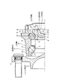
図1〜2は、前記(1)(2)の構成要件を組み込んだ、本発明の実施例1を示している。尚、本発明の特徴は、シャフト部材2に対して内輪3を固定する部分の構造にある。その他の部分の構造及び作用に就いては、前述の図8に示した従来構造と同様であるから、重複する説明を省略若しくは簡略にし、以下、本発明の特徴部分を中心に説明する。
FIGS. 1-2 has shown Example 1 of this invention incorporating the structural requirements of said (1) (2). The feature of the present invention lies in the structure of the portion for fixing the
シャフト部材2の内端部に形成した段部8の中間部内端寄り部分で、この段部8に外嵌した内輪3の内端部内周面に、内端開口に向かう程内径が大きくなる、円錐凹面状の傾斜面19を形成している。この傾斜面19が上記シャフト部材2の中心軸に対し傾斜している傾斜角度θは、20〜60度程度とする。又、上記シャフト部材2の内端面には円形の凹部20を形成する事により、このシャフト部材2の内端部に円筒部21を形成している。本実施例の場合にこの円筒部21は、上記シャフト部材2の内端部で、ほぼ上記内輪3の肩部23の内側部分に存在する。
The inner diameter increases toward the inner end opening on the inner peripheral surface of the
上述の様な傾斜面19を形成した内輪3を、上記シャフト部材2の内端部に設けた円筒部21をかしめ広げる事によりこのシャフト部材2に固定し、本発明の車輪支持用転がり軸受ユニットとする際には、前記図9に示した従来構造の場合に比べて、かしめ部分の変形量が少なくて済む。即ち、上記従来構造の場合にはかしめ部16を形成する為、シャフト部材2の内端部に形成した円筒部を直径方向外方に向け、90度折り曲げるのに対して、本発明の車輪支持用転がり軸受ユニットを構成すべく、上記円筒部21をかしめ広げる際には、この円筒部21を上記傾斜角度θ(=20〜60度)だけ変形させれば良い。この為、このかしめ部分に発生する歪みを小さく抑えて、このかしめ部に割れ等の損傷が発生するのを抑える事ができる。又、上記変形量を少なく抑える為、このかしめ部を形成する事に基づき、上記円筒部21の周囲に存在する部材である上記内輪3に、この内輪3の直径方向外方に加わる力を低減できて、この内輪3の損傷防止を図れる。
The
尚、上記円筒部21を直径方向外方にかしめ広げる作業は、鍛造加工、或は揺動プレス加工により行なう。何れの加工法を採用する場合でも、図2に示す様に、上記円筒部21の内径側にプレス型25を押し込み、上記円筒部21を直径方向外方にかしめ広げる。特に、かしめ作業に揺動プレス加工を採用すれば、成形時の荷重を小さくして、軸受内部への影響をなくし、成形後の予圧管理を適正にできると言った利点がある。又、上記円筒部21の奥端縁(この円筒部21の内径が変化しない部分の奥端)と上記内輪3の端面24との距離Lは、車輪支持用転がり軸受ユニットの大きさ等の応じて設計的に定めるが、一般的な乗用車用の車輪支持用転がり軸受ユニットの場合で、5〜15mm程度とするのが好ましい。
The operation of caulking the
又、上記円筒部21を構成すべく、上記シャフト部材2の端部に形成する円形の凹部20の先端位置は、複列に配置した転動体5、5のうち、内側の列を構成する転動体5の中心よりも内側に位置させている。即ち、図1に点Xで示した、上記凹部20の先端の、上記シャフト部材2の軸方向に関する位置は、第二の内輪軌道である、上記内輪3の外周面に設けた第二の内輪軌道9に当接する転動体5の中心の、上記シャフト部材2の軸方向に関する位置よりも、上記シャフト部材2の内端部側に位置させている。従って、車輪支持用転がり軸受ユニットを構成するシャフト部材2と外輪4との間にラジアル荷重が加わり、上記転動体5から上記第二の内輪軌道9にラジアル荷重が加わった場合でも、上記シャフト部材2の一部でこのラジアル荷重を受ける部分が充実体である為、このシャフト部材2の耐久性を十分に確保できる。
Further, in order to form the
更に、上記第二の内輪軌道9に当接する転動体5の中心と、上記内輪3の端面24との、上記シャフト部材2の軸方向に関する距離Mを、上記各転動体5、5の外径Dの0.75倍以上(M≧0.75D)としている。この様に、転動体5の中心と端面24との距離Mを確保している為、上記内輪3の肩部23や第二の内輪軌道9部分の寸法精度や形状精度が悪化する事を防止して、車輪支持用転がり軸受ユニットの機能を確保できる。即ち、これら各部分の寸法精度や形状精度を良好に確保できるので、車輪支持用転がり軸受ユニットの運転時に振動等が発生するのを防止すると共に、転動体5の転動面や第二の内輪軌道9の転がり疲れ寿命等を確保できる。尚、図示の例では、第一の内輪軌道7をシャフト部材2の中間部外周面に直接形成しているが、この第一の内輪軌道7は、シャフト部材2と別体の内輪に形成し、この内輪をこのシャフト部材2に外嵌固定しても良い。
Further, the distance M in the axial direction of the
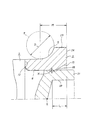
次に、図3は、前記(1)(2)(6)の構成要件を組み込んだ、本発明の実施例2を示している。本実施例の場合には、シャフト部材2の内端部で、このシャフト部材2に外嵌した内輪3の端面24よりも内方に突出した部分に、スペーサリング18を外嵌している。このスペーサリング18の内半部内周面には、内端開口に向かう程内径が大きくなる、円錐凹面状の傾斜面19を形成している。そして、上記シャフト部材2の内端部で上記スペーサリング18の内側に存在する円筒部21を直径方向外方にかしめ広げる事により、上記スペーサリング18を上記内輪3の端面24に向け抑え付けて、この内輪3を上記シャフト部材2に結合固定している。又、第二の内輪軌道9と第二の外輪軌道14との間に設けた転動体5から内輪3に加わる荷重の作用線(接触角を表す鎖線αと一致する)の延長位置は、上記傾斜面19よりも段部8の軸方向中央寄りで、外径が変化しない部分に存在する。
Next, FIG. 3 shows
本実施例の場合、この様なスペーサリング18を設ける事により、上記円筒部21をかしめ広げる際のかしめ強度を十分に大きくした場合でも、上記内輪3が直径方向に弾性変形する事を確実に防止できる。即ち、本実施例の場合には、上記円筒部21をかしめ広げる際に加わる、直径方向外方に向いた力は、シャフト部材2に外嵌したスペーサリング18が受ける。従って、上記円筒部21をかしめ広げる作業に伴って、上記内輪3の直径が変化する事が、前述した第1例の場合よりも少なくなる(殆ど変化しなくなる)。尚、仮にスペーサリング18の寸法精度、及び形状精度が悪化しても、車輪支持用転がり軸受ユニットの性能には何らの悪影響も及ぼさない。又、本実施例の場合には、上記荷重の作用線の延長位置を規制している為、この荷重が上記円筒部21をかしめ広げた部分に作用する事を防止して、かしめ固定部分の耐久性を確保できる。スペーサリング18を設けた点、並びに作用線の延長位置を規制した点以外の構成及び作用は、前述した実施例1の場合と同様である。
In the case of the present embodiment, by providing such a
次に、図4は、前記(1)(2)(3)(6)の構成要件を組み込んだ、本発明の実施例3を示している。本実施例の場合には、シャフト部材2の内端部に外嵌した内輪3aの内端部で傾斜面19を形成した部分の外径を、この内輪3aの肩部23の外径よりも小さくして、内輪円筒部26としている。この様な本実施例の場合、上記シャフト部材2の内端部に形成した円筒部21を、上記傾斜面19に向けて直径方向外方にかしめ広げ、上記内輪3をシャフト部材2に固定する際には、上記内輪円筒部26が、かしめ広げに伴う応力の大部分を受ける。従って、肩部23に比較して薄肉の内輪円筒部26の変形量は多くなるが、上記内輪3aの肩部23及び第二の内輪軌道9の変形量を小さくできる。この結果、車輪支持用転がり軸受ユニットの回転精度を十分良好な状態に維持できる。尚、本実施例の場合には、上記第二の内輪軌道9に当接する転動体5の中心と、上記内輪3aの肩部23の端面24aとの、上記シャフト部材2の軸方向に関する距離Mを、上記各転動体5、5の外径Dの0.75倍以上(M≧0.75D)としている。又、本実施例の場合も、荷重の作用線の延長位置を規制して、かしめ固定部分の耐久性確保を図っている。その他の構成及び作用は、前述した実施例1の場合と同様である。
Next, FIG. 4 shows
次に、図5は、前記(1)(2)の構成要件を組み込んだ、本発明の実施例4を示している。上述した実施例1〜3の場合には、外輪4を回転しない静止輪とし、シャフト部材2を回転させる構造であったのに対して、本実施例の場合には、シャフト部材2を懸架装置に支持して回転させず、外輪4を車輪と共に回転する回転輪としている。回転側と静止側とが逆になった以外の構成及び作用は、前述した実施例1の場合と同様である。
Next, FIG. 5 shows
次に、図6は、前記(1)(2)(4)の構成要件を組み込んだ、本発明の実施例5を示している。本実施例の場合、シャフト部材2の内端部で内輪3の嵌合部よりも突出した部分の外径を、この嵌合部の外径よりも小さくしている。即ち、上記シャフト部材2の内端部に形成した円筒部21の基端部外周面で、この内輪3の内端開口部に形成した傾斜面19よりも少しだけ第二の内輪軌道9に寄った部分に、0.02〜1mm程度の僅かな段差Hを有する段差部27を形成している。そして、上記円筒部21のうちの外径の小さくなった部分を、直径方向外方にかしめ広げ、上記傾斜面19を抑え付ける様にしている。この様に円筒部21を直径方向外方にかしめ広げる際には、上記段差部27がかしめ広げ作業に伴って折れ曲がる部分の起点となる。この為、かしめ広げ作業に伴って上記円筒部21に無理な力が加わりにくくなって、かしめ広げ部分に亀裂等の損傷が発生しにくくなる。その他の構成及び作用は、前述した実施例1の場合と同様である。尚、本実施例の構造を上述した実施例4に適用する場合には、軸方向に関する内外方向が逆になる。
Next, FIG. 6 shows
次に、図7は、前記(1)(2)(5)の構成要件を組み込んだ、本発明の実施例6を示している。本実施例の場合、シャフト部材2の内端部外周面の一部で、内輪3の内端部に形成した傾斜面19の小径側端部に対向する部分に、0.1〜2mm程度の深さKを有する凹溝28を、上記外周面の全周に亙って形成している。そして、上記シャフト部材2の内端部に形成した円筒部21のうちの上記凹溝28よりも内端寄り部分を、直径方向外方にかしめ広げ、上記傾斜面19を抑え付ける様にしている。この様に円筒部21を直径方向外方にかしめ広げる際には、上記凹溝28がかしめ広げ作業に伴って折れ曲がる部分の起点となる。この為、かしめ広げ作業に伴って上記円筒部21に無理な力が加わりにくくなって、かしめ広げ部分に亀裂等の損傷が発生しにくくなる。その他の構成及び作用は、前述した実施例1の場合と同様である。尚、本実施例の構造を上述した実施例4に適用する場合にも、軸方向に関する内外方向が逆になる。
Next, FIG. 7 shows
1 車輪支持用転がり軸受ユニット
2 シャフト部材
3、3a 内輪
4 外輪
5 転動体
6 第二のフランジ
7 第一の内輪軌道
8 段部
9 第二の内輪軌道
10 雄ねじ部
11 ナット
12 段差面
13 第一の外輪軌道
14 第二の外輪軌道
15 第一のフランジ
16 かしめ部
17 係止凹部
18 スぺーサリング
19 傾斜面
20 凹部
21 円筒部
22 シールリング
23 肩部
24、24a 端面
25 プレス型
26 内輪円筒部
27 段差部
28 凹溝
29 蓋体
DESCRIPTION OF SYMBOLS 1 Rolling bearing unit for
Claims (1)
Priority Applications (1)
| Application Number | Priority Date | Filing Date | Title |
|---|---|---|---|
| JP2005177772A JP4186959B2 (en) | 2005-06-17 | 2005-06-17 | Rolling bearing unit for wheel support |
Applications Claiming Priority (1)
| Application Number | Priority Date | Filing Date | Title |
|---|---|---|---|
| JP2005177772A JP4186959B2 (en) | 2005-06-17 | 2005-06-17 | Rolling bearing unit for wheel support |
Related Parent Applications (1)
| Application Number | Title | Priority Date | Filing Date |
|---|---|---|---|
| JP25304896A Division JP3855315B2 (en) | 1996-09-25 | 1996-09-25 | Manufacturing method of wheel bearing rolling bearing unit |
Publications (2)
| Publication Number | Publication Date |
|---|---|
| JP2005291501A true JP2005291501A (en) | 2005-10-20 |
| JP4186959B2 JP4186959B2 (en) | 2008-11-26 |
Family
ID=35324634
Family Applications (1)
| Application Number | Title | Priority Date | Filing Date |
|---|---|---|---|
| JP2005177772A Expired - Fee Related JP4186959B2 (en) | 2005-06-17 | 2005-06-17 | Rolling bearing unit for wheel support |
Country Status (1)
| Country | Link |
|---|---|
| JP (1) | JP4186959B2 (en) |
-
2005
- 2005-06-17 JP JP2005177772A patent/JP4186959B2/en not_active Expired - Fee Related
Also Published As
| Publication number | Publication date |
|---|---|
| JP4186959B2 (en) | 2008-11-26 |
Similar Documents
| Publication | Publication Date | Title |
|---|---|---|
| JP3855315B2 (en) | Manufacturing method of wheel bearing rolling bearing unit | |
| JPH10196661A (en) | Hub unit for wheel support | |
| US20100278468A1 (en) | Wheel support bearing assembly and method of making the same | |
| JP3815376B2 (en) | Rolling bearing unit for wheel support | |
| JP6555426B2 (en) | Hub unit bearing and manufacturing method thereof, and automobile and manufacturing method thereof | |
| JPH115404A (en) | Hub unit for wheel support | |
| JP2005212713A (en) | Wheel bearing device | |
| WO2008018175A1 (en) | Bearing device for wheel | |
| JP2008190558A (en) | Axle bearing device | |
| JP3601537B2 (en) | Rolling bearing unit for wheel support | |
| JP2004132552A (en) | Rolling bearing unit for wheel support | |
| JP2005291501A (en) | Rolling bearing unit for wheel support | |
| JP4519003B2 (en) | Wheel bearing device | |
| JP4059268B2 (en) | Rolling bearing unit for wheel support and manufacturing method thereof | |
| JP4682459B2 (en) | Manufacturing method of wheel bearing rolling bearing unit | |
| JP4519004B2 (en) | Wheel bearing device | |
| JP4519005B2 (en) | Wheel bearing device | |
| JP4453033B2 (en) | Manufacturing method of wheel supporting hub unit | |
| JP4467480B2 (en) | Wheel bearing device and caulking method thereof | |
| JP2007292142A (en) | Wheel support bearing unit | |
| JP2003056580A (en) | Bearing device for axle | |
| JP2000229501A (en) | Hub unit for wheel support | |
| JP2006144990A (en) | Rolling bearing device | |
| JP2005289147A (en) | Bearing device for wheel | |
| JP4576704B2 (en) | Rolling bearing unit for wheel support |
Legal Events
| Date | Code | Title | Description |
|---|---|---|---|
| RD04 | Notification of resignation of power of attorney |
Free format text: JAPANESE INTERMEDIATE CODE: A7424 Effective date: 20070515 |
|
| TRDD | Decision of grant or rejection written | ||
| A01 | Written decision to grant a patent or to grant a registration (utility model) |
Free format text: JAPANESE INTERMEDIATE CODE: A01 Effective date: 20080819 |
|
| A01 | Written decision to grant a patent or to grant a registration (utility model) |
Free format text: JAPANESE INTERMEDIATE CODE: A01 |
|
| A61 | First payment of annual fees (during grant procedure) |
Free format text: JAPANESE INTERMEDIATE CODE: A61 Effective date: 20080901 |
|
| R150 | Certificate of patent or registration of utility model |
Free format text: JAPANESE INTERMEDIATE CODE: R150 |
|
| FPAY | Renewal fee payment (event date is renewal date of database) |
Free format text: PAYMENT UNTIL: 20110919 Year of fee payment: 3 |
|
| FPAY | Renewal fee payment (event date is renewal date of database) |
Free format text: PAYMENT UNTIL: 20110919 Year of fee payment: 3 |
|
| FPAY | Renewal fee payment (event date is renewal date of database) |
Free format text: PAYMENT UNTIL: 20120919 Year of fee payment: 4 |
|
| FPAY | Renewal fee payment (event date is renewal date of database) |
Free format text: PAYMENT UNTIL: 20120919 Year of fee payment: 4 |
|
| FPAY | Renewal fee payment (event date is renewal date of database) |
Free format text: PAYMENT UNTIL: 20130919 Year of fee payment: 5 |
|
| LAPS | Cancellation because of no payment of annual fees |