JP2005291501A - 車輪支持用転がり軸受ユニット - Google Patents
車輪支持用転がり軸受ユニット Download PDFInfo
- Publication number
- JP2005291501A JP2005291501A JP2005177772A JP2005177772A JP2005291501A JP 2005291501 A JP2005291501 A JP 2005291501A JP 2005177772 A JP2005177772 A JP 2005177772A JP 2005177772 A JP2005177772 A JP 2005177772A JP 2005291501 A JP2005291501 A JP 2005291501A
- Authority
- JP
- Japan
- Prior art keywords
- inner ring
- shaft member
- ring
- peripheral surface
- caulking
- Prior art date
- Legal status (The legal status is an assumption and is not a legal conclusion. Google has not performed a legal analysis and makes no representation as to the accuracy of the status listed.)
- Granted
Links
Images


Classifications
-
- F—MECHANICAL ENGINEERING; LIGHTING; HEATING; WEAPONS; BLASTING
- F16—ENGINEERING ELEMENTS AND UNITS; GENERAL MEASURES FOR PRODUCING AND MAINTAINING EFFECTIVE FUNCTIONING OF MACHINES OR INSTALLATIONS; THERMAL INSULATION IN GENERAL
- F16C—SHAFTS; FLEXIBLE SHAFTS; ELEMENTS OR CRANKSHAFT MECHANISMS; ROTARY BODIES OTHER THAN GEARING ELEMENTS; BEARINGS
- F16C43/00—Assembling bearings
- F16C43/04—Assembling rolling-contact bearings
-
- F—MECHANICAL ENGINEERING; LIGHTING; HEATING; WEAPONS; BLASTING
- F16—ENGINEERING ELEMENTS AND UNITS; GENERAL MEASURES FOR PRODUCING AND MAINTAINING EFFECTIVE FUNCTIONING OF MACHINES OR INSTALLATIONS; THERMAL INSULATION IN GENERAL
- F16C—SHAFTS; FLEXIBLE SHAFTS; ELEMENTS OR CRANKSHAFT MECHANISMS; ROTARY BODIES OTHER THAN GEARING ELEMENTS; BEARINGS
- F16C19/00—Bearings with rolling contact, for exclusively rotary movement
- F16C19/02—Bearings with rolling contact, for exclusively rotary movement with bearing balls essentially of the same size in one or more circular rows
- F16C19/14—Bearings with rolling contact, for exclusively rotary movement with bearing balls essentially of the same size in one or more circular rows for both radial and axial load
- F16C19/18—Bearings with rolling contact, for exclusively rotary movement with bearing balls essentially of the same size in one or more circular rows for both radial and axial load with two or more rows of balls
- F16C19/181—Bearings with rolling contact, for exclusively rotary movement with bearing balls essentially of the same size in one or more circular rows for both radial and axial load with two or more rows of balls with angular contact
- F16C19/183—Bearings with rolling contact, for exclusively rotary movement with bearing balls essentially of the same size in one or more circular rows for both radial and axial load with two or more rows of balls with angular contact with two rows at opposite angles
- F16C19/184—Bearings with rolling contact, for exclusively rotary movement with bearing balls essentially of the same size in one or more circular rows for both radial and axial load with two or more rows of balls with angular contact with two rows at opposite angles in O-arrangement
- F16C19/186—Bearings with rolling contact, for exclusively rotary movement with bearing balls essentially of the same size in one or more circular rows for both radial and axial load with two or more rows of balls with angular contact with two rows at opposite angles in O-arrangement with three raceways provided integrally on parts other than race rings, e.g. third generation hubs
-
- F—MECHANICAL ENGINEERING; LIGHTING; HEATING; WEAPONS; BLASTING
- F16—ENGINEERING ELEMENTS AND UNITS; GENERAL MEASURES FOR PRODUCING AND MAINTAINING EFFECTIVE FUNCTIONING OF MACHINES OR INSTALLATIONS; THERMAL INSULATION IN GENERAL
- F16C—SHAFTS; FLEXIBLE SHAFTS; ELEMENTS OR CRANKSHAFT MECHANISMS; ROTARY BODIES OTHER THAN GEARING ELEMENTS; BEARINGS
- F16C2326/00—Articles relating to transporting
- F16C2326/01—Parts of vehicles in general
- F16C2326/02—Wheel hubs or castors
Landscapes
- Engineering & Computer Science (AREA)
- General Engineering & Computer Science (AREA)
- Mechanical Engineering (AREA)
- Mounting Of Bearings Or Others (AREA)
- Rolling Contact Bearings (AREA)
Abstract
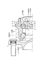
【解決手段】 内輪3の端部内周面に傾斜面19を形成し、この傾斜面19に向けて、上記円筒部21をかしめ広げる。この円筒部21の変形量が少なく、かしめ広げ部分を損傷しにくくすると共に、上記内輪3の変形量を少なく抑える事もできる。
【選択図】 図1
Description
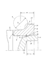
特に、本発明の車輪支持用転がり軸受ユニットに於いては、上記内輪若しくはこの内輪よりも上記シャフト部材の先端寄りに外嵌したスペーサリングの開口周縁部で上記円筒部をかしめ広げた部分の外周面が押し付けられる部分を、開口端に向かう程内径が大きくなる、円錐凹面状の傾斜面としている。
特に、本発明の車輪支持用転がり軸受ユニットの場合には、シャフト部材の端部に形成した円筒部をかしめ広げた部分の外周面が押し付けられる部分を、開口端に向かう程内径が大きくなる、円錐凹面状の傾斜面としている為、このかしめ部分の変形量が少なくて済む。この為、このかしめ部分に発生する歪みを小さく抑えて、このかしめ部に割れ等の損傷が発生するのを抑える事ができる。又、上記変形量を少なく抑える為、このかしめ部を形成する事に基づき、上記円筒部の周囲に存在する部材にその直径方向外方に加わる力を低減できる。この結果、スペーサリングを用いた場合は勿論、スペーサリングを用いない場合でも、内輪にその直径方向外方に加わる力を低減して、この内輪の損傷防止を図れる。
本発明の車輪支持用転がり軸受ユニットは、上述の様に構成され作用するので、内輪の直径が変化する事を防止して、この内輪及びこの内輪を固定する為のかしめ広げ部分が、上記内輪の固定作業に基づいて損傷する可能性を低くできる。又、予圧を適正値に維持でき、しかも部品点数、部品加工、組立工数の減少により、コスト低減を図れる。
(1) 上記円筒部を構成すべく、上記シャフト部材の端部に形成する円形の凹部の先端の、このシャフト部材の軸方向に関する位置は、上記第二の内輪軌道に当接する転動体の中心の上記シャフト部材の軸方向に関する位置よりも、上記シャフト部材の端部側に位置する。
(2) 上記第二の内輪軌道に当接する転動体の中心と、上記内輪の端面若しくはこの内輪の肩部の端面との、上記シャフト部材の軸方向に関する距離は、上記転動体の外径の0.75倍以上である。
(3) 上記内輪の端部で上記傾斜面を形成した部分の外径を、この内輪の肩部の外径よりも小さくする。
(4) 上記シャフト部材の先端部で上記内輪の嵌合部、若しくは内輪及びスペーサリングの嵌合部よりも突出した部分の外径を、この嵌合部の外径よりも小さくし、上記シャフト部材の端部に形成した円筒部のうちの外径の小さくなった部分を、直径方向外方にかしめ広げる。
(5) 上記シャフト部材の先端部外周面の一部で、上記傾斜面の小径側端部に対向する部分に凹溝を、上記外周面の全周に亙って形成し、上記シャフト部材の端部に形成した円筒部のうちの凹溝よりも先端寄り部分を、直径方向外方にかしめ広げる。
(6) 転動体から内輪に加わる荷重の作用線の延長位置を、上記傾斜面よりもシャフト部材の軸方向中央寄りで、このシャフト部材の外径が変化しない部分に存在させる。
2 シャフト部材
3、3a 内輪
4 外輪
5 転動体
6 第二のフランジ
7 第一の内輪軌道
8 段部
9 第二の内輪軌道
10 雄ねじ部
11 ナット
12 段差面
13 第一の外輪軌道
14 第二の外輪軌道
15 第一のフランジ
16 かしめ部
17 係止凹部
18 スぺーサリング
19 傾斜面
20 凹部
21 円筒部
22 シールリング
23 肩部
24、24a 端面
25 プレス型
26 内輪円筒部
27 段差部
28 凹溝
29 蓋体
Claims (1)
- 外周面に第一のフランジを、内周面に複列の外輪軌道を、それぞれ設けた外輪と、端部外周面に第二のフランジを設けたシャフト部材と、外周面に内輪軌道を有し上記シャフト部材に外嵌した、少なくとも1個の内輪と、この内輪を含んで上記シャフト部材と共に回転する部分の外周面に設けた第一、第二の内輪軌道と上記複列の外輪軌道との間に、それぞれ複数個ずつ設けた転動体とを備え、上記シャフト部材の端部に形成した円筒部の一部で上記内輪よりも突出した部分を直径方向外方にかしめ広げ、このかしめ広げた部分により上記内輪を直接又はスペーサリングを介して抑え付ける事により、上記内輪を上記シャフト部材に固定する車輪支持用転がり軸受ユニットに於いて、上記内輪若しくはこの内輪よりも上記シャフト部材の先端寄りに外嵌したスペーサリングの開口周縁部で上記円筒部をかしめ広げた部分の外周面が押し付けられる部分を、開口端に向かう程内径が大きくなる、円錐凹面状の傾斜面とした事を特徴とする車輪支持用転がり軸受ユニット。
Priority Applications (1)
| Application Number | Priority Date | Filing Date | Title |
|---|---|---|---|
| JP2005177772A JP4186959B2 (ja) | 2005-06-17 | 2005-06-17 | 車輪支持用転がり軸受ユニット |
Applications Claiming Priority (1)
| Application Number | Priority Date | Filing Date | Title |
|---|---|---|---|
| JP2005177772A JP4186959B2 (ja) | 2005-06-17 | 2005-06-17 | 車輪支持用転がり軸受ユニット |
Related Parent Applications (1)
| Application Number | Title | Priority Date | Filing Date |
|---|---|---|---|
| JP25304896A Division JP3855315B2 (ja) | 1996-09-25 | 1996-09-25 | 車輪支持用転がり軸受ユニットの製造方法 |
Publications (2)
| Publication Number | Publication Date |
|---|---|
| JP2005291501A true JP2005291501A (ja) | 2005-10-20 |
| JP4186959B2 JP4186959B2 (ja) | 2008-11-26 |
Family
ID=35324634
Family Applications (1)
| Application Number | Title | Priority Date | Filing Date |
|---|---|---|---|
| JP2005177772A Expired - Fee Related JP4186959B2 (ja) | 2005-06-17 | 2005-06-17 | 車輪支持用転がり軸受ユニット |
Country Status (1)
| Country | Link |
|---|---|
| JP (1) | JP4186959B2 (ja) |
-
2005
- 2005-06-17 JP JP2005177772A patent/JP4186959B2/ja not_active Expired - Fee Related
Also Published As
| Publication number | Publication date |
|---|---|
| JP4186959B2 (ja) | 2008-11-26 |
Similar Documents
| Publication | Publication Date | Title |
|---|---|---|
| JP3855315B2 (ja) | 車輪支持用転がり軸受ユニットの製造方法 | |
| JPH10196661A (ja) | 車輪支持用ハブユニット | |
| US20100278468A1 (en) | Wheel support bearing assembly and method of making the same | |
| JP3815376B2 (ja) | 車輪支持用転がり軸受ユニット | |
| JP6555426B2 (ja) | ハブユニット軸受およびその製造方法、並びに、自動車およびその製造方法 | |
| JPH115404A (ja) | 車輪支持用ハブユニット | |
| JP2005212713A (ja) | 車輪用軸受装置 | |
| WO2008018175A1 (en) | Bearing device for wheel | |
| JP2008190558A (ja) | 車軸用軸受装置 | |
| JP3601537B2 (ja) | 車輪支持用転がり軸受ユニット | |
| JP2004132552A (ja) | 車輪支持用転がり軸受ユニット | |
| JP2005291501A (ja) | 車輪支持用転がり軸受ユニット | |
| JP4519003B2 (ja) | 車輪用軸受装置 | |
| JP4059268B2 (ja) | 車輪支持用転がり軸受ユニット及びその製造方法 | |
| JP4682459B2 (ja) | 車輪支持用転がり軸受ユニットの製造方法 | |
| JP4519004B2 (ja) | 車輪用軸受装置 | |
| JP4519005B2 (ja) | 車輪用軸受装置 | |
| JP4453033B2 (ja) | 車輪支持用ハブユニットの製造方法 | |
| JP4467480B2 (ja) | 車輪用軸受装置およびその加締加工方法 | |
| JP2007292142A (ja) | 車輪支持用軸受ユニット | |
| JP2003056580A (ja) | 車軸用軸受装置 | |
| JP2000229501A (ja) | 車輪支持用ハブユニット | |
| JP2006144990A (ja) | 転がり軸受装置 | |
| JP2005289147A (ja) | 車輪用軸受装置 | |
| JP4576704B2 (ja) | 車輪支持用転がり軸受ユニット |
Legal Events
| Date | Code | Title | Description |
|---|---|---|---|
| RD04 | Notification of resignation of power of attorney |
Free format text: JAPANESE INTERMEDIATE CODE: A7424 Effective date: 20070515 |
|
| TRDD | Decision of grant or rejection written | ||
| A01 | Written decision to grant a patent or to grant a registration (utility model) |
Free format text: JAPANESE INTERMEDIATE CODE: A01 Effective date: 20080819 |
|
| A01 | Written decision to grant a patent or to grant a registration (utility model) |
Free format text: JAPANESE INTERMEDIATE CODE: A01 |
|
| A61 | First payment of annual fees (during grant procedure) |
Free format text: JAPANESE INTERMEDIATE CODE: A61 Effective date: 20080901 |
|
| R150 | Certificate of patent or registration of utility model |
Free format text: JAPANESE INTERMEDIATE CODE: R150 |
|
| FPAY | Renewal fee payment (event date is renewal date of database) |
Free format text: PAYMENT UNTIL: 20110919 Year of fee payment: 3 |
|
| FPAY | Renewal fee payment (event date is renewal date of database) |
Free format text: PAYMENT UNTIL: 20110919 Year of fee payment: 3 |
|
| FPAY | Renewal fee payment (event date is renewal date of database) |
Free format text: PAYMENT UNTIL: 20120919 Year of fee payment: 4 |
|
| FPAY | Renewal fee payment (event date is renewal date of database) |
Free format text: PAYMENT UNTIL: 20120919 Year of fee payment: 4 |
|
| FPAY | Renewal fee payment (event date is renewal date of database) |
Free format text: PAYMENT UNTIL: 20130919 Year of fee payment: 5 |
|
| LAPS | Cancellation because of no payment of annual fees |