JP2005296037A - Game machine - Google Patents
Game machine Download PDFInfo
- Publication number
- JP2005296037A JP2005296037A JP2004112050A JP2004112050A JP2005296037A JP 2005296037 A JP2005296037 A JP 2005296037A JP 2004112050 A JP2004112050 A JP 2004112050A JP 2004112050 A JP2004112050 A JP 2004112050A JP 2005296037 A JP2005296037 A JP 2005296037A
- Authority
- JP
- Japan
- Prior art keywords
- rotating member
- gap
- gap filling
- rotation
- game
- Prior art date
- Legal status (The legal status is an assumption and is not a legal conclusion. Google has not performed a legal analysis and makes no representation as to the accuracy of the status listed.)
- Pending
Links
- 230000001105 regulatory effect Effects 0.000 claims abstract description 17
- 230000001276 controlling effect Effects 0.000 claims abstract description 7
- 238000010304 firing Methods 0.000 claims description 23
- 230000037431 insertion Effects 0.000 abstract description 4
- 238000003780 insertion Methods 0.000 abstract description 4
- 210000003811 finger Anatomy 0.000 description 8
- 239000000463 material Substances 0.000 description 4
- 239000011521 glass Substances 0.000 description 2
- 239000004973 liquid crystal related substance Substances 0.000 description 2
- 239000007769 metal material Substances 0.000 description 2
- 230000002093 peripheral effect Effects 0.000 description 2
- 239000011347 resin Substances 0.000 description 2
- 229920005989 resin Polymers 0.000 description 2
- 235000019504 cigarettes Nutrition 0.000 description 1
- 239000004020 conductor Substances 0.000 description 1
- 210000004932 little finger Anatomy 0.000 description 1
- 239000004065 semiconductor Substances 0.000 description 1
- 210000003813 thumb Anatomy 0.000 description 1
Images

Landscapes
- Pinball Game Machines (AREA)
Abstract
Description
本発明は、パチンコ機等の遊技機に関し、特に、遊技球を発射する発射装置を操作する発射ハンドルを備えた遊技機に関する。 The present invention relates to a gaming machine such as a pachinko machine, and more particularly to a gaming machine provided with a launching handle for operating a launching device that launches a game ball.
従来、遊技機は、遊技部材を設けてある遊技盤に遊技球を発射する発射装置を操作する発射ハンドルを備えている。発射ハンドルは、主として、発射装置が遊技球を発射する勢いを回転角に基づいて制御可能な回転部材と、この回転部材がスラスト方向へ移動するのを回転部材のスラスト方向の両側から規制する1対の規制部材等で構成されている(特許文献1参照)。そして、回転部材が円滑に回転できるように、規制部材と回転部材との間に僅かな隙間を設けてある。 2. Description of the Related Art Conventionally, a gaming machine has a firing handle for operating a launching device that launches a game ball onto a game board provided with a game member. The firing handle mainly restricts the rotating member that can control the momentum at which the launching device launches the game ball based on the rotation angle, and restricts the rotational member from moving on both sides of the rotating member in the thrust direction. It consists of a pair of restricting members or the like (see Patent Document 1). A slight gap is provided between the regulating member and the rotating member so that the rotating member can rotate smoothly.
また、発射ハンドルは、遊技者によって回転部材が復帰ばねに抗して回転されると、その回転角に応じて、発射装置の発射力を変えるようになっている。復帰ばねは、回転部材を回転開始位置に復帰回転させるようになっている。 In addition, when the rotating member is rotated against the return spring by the player, the launching handle changes the firing force of the launching device in accordance with the rotation angle. The return spring is configured to return and rotate the rotating member to the rotation start position.
このため、遊技者は、遊技を開始して間もない間、遊技部材の入賞口に入賞する遊技球の割合が最も高い発射ハンドルの最適な回転位置を探し出し、その後、その最適な回転位置を微調整しながら発射ハンドルを保持し続けて、遊技を継続することが多い。 For this reason, the player finds the optimum rotation position of the launching handle having the highest percentage of game balls to be won in the prize opening of the gaming member shortly after starting the game, and then determines the optimum rotation position. The game is often continued by holding the launch handle while making fine adjustments.
ところで、遊技者が、遊技中、遊技機から離れて、タバコを購入したり、休憩したりすることがある。このようなとき、遊技者が発射ハンドルから手を離すため、回転部材は復帰ばねによって、回転開始位置に復帰回転することになる。このため、遊技者によっては、遊技機に戻ったとき、再度、最適な回転位置を探し出す手間を省く目的で、回転部材と規制部材との隙間にコイン等の挿入物を無理に押し込んで回転部材を最適な回転位置に仮固定してから、遊技機を離れることがある。 By the way, during the game, the player may leave the gaming machine and purchase cigarettes or take a break. In such a case, since the player releases his hand from the firing handle, the rotating member is rotated back to the rotation start position by the return spring. Therefore, depending on the player, when returning to the gaming machine, for the purpose of saving the trouble of finding the optimum rotation position again, the insertion member such as a coin is forcibly pushed into the gap between the rotation member and the regulating member. May be temporarily fixed at the optimum rotational position and then left the gaming machine.
なお、遊技機は、遊技者が発射ハンドルから手を離すと、回転部材が復帰ばねによって回転開始位置に復帰回転して発射装置が発射動作を停止させるようになっている。 In the gaming machine, when the player releases his hand from the firing handle, the rotating member returns to the rotation start position by the return spring and the launching device stops the firing operation.
このように、従来の遊技機は、回転部材と規制部材との間に挿入物をこじるようにして無理に挿入されることがあり、発射ハンドルに損傷を受けて操作不能になるという問題があった。 As described above, the conventional gaming machine may be forcibly inserted by inserting an insert between the rotating member and the regulating member, and there is a problem that the launching handle is damaged and becomes inoperable. It was.
本発明は、規制部材と回転部材との隙間に挿入物が挿入されにくいようにした遊技機を提供することを目的としている。 An object of the present invention is to provide a gaming machine in which an insert is hardly inserted into a gap between a regulating member and a rotating member.
請求項1に係る発明は、遊技物を有する遊技盤(16)と、前記遊技盤(16)に遊技球を発射する発射装置(31)と、前記発射装置(31)が遊技球を発射する勢いを回転角に基づいて制御可能な発射ハンドル(41)と、を備えた遊技機(11)において、前記発射ハンドル(41)が、前記発射装置(31)が遊技球を発射する勢いを回転角に基づいて制御可能な回転部材(45)と、前記回転部材(45)がスラスト方向へ移動するのを前記回転部材(45)の前記スラスト方向の両側から規制する1対の規制部材(43,44)とを備え、前記1対の規制部材(43,44)の少なくとも一方の規制部材(43,44)と前記回転部材(45)との隙間に、該隙間を埋める隙間埋め部材(51,52)を設け、該隙間埋め部材(51,52)が前記隙間に挿入物を挿入されるのを阻止することを特徴とする遊技機(11)である。 The invention according to claim 1 is a game board (16) having a game, a launcher (31) for launching a game ball on the game board (16), and the launcher (31) launching a game ball. In a gaming machine (11) comprising a firing handle (41) capable of controlling momentum based on a rotation angle, the firing handle (41) rotates the momentum at which the launching device (31) launches a game ball. A rotating member (45) that can be controlled based on an angle, and a pair of regulating members (43) that regulate the movement of the rotating member (45) in the thrust direction from both sides in the thrust direction of the rotating member (45). , 44), and a gap filling member (51) filling the gap between at least one of the pair of regulating members (43, 44) and the rotating member (45). , 52) and the gap filling member ( 1, 52) is a game machine (11), characterized in that to prevent from being inserted an insert into the gap.
請求項2に係る発明は、前記隙間埋め部材(51,52)の厚みが、前記回転部材(45)の回転を許容する厚みであることを特徴とする請求項1に記載の遊技機(11)である。 The invention according to claim 2 is the gaming machine (11) according to claim 1, wherein the gap filling member (51, 52) has a thickness that allows rotation of the rotating member (45). ).
請求項3に係る発明は、前記回転部材(45)を回転可能に支持する回転支持部(63,64)を前記1対の規制部材(43,44)の間に設け、かつ前記隙間埋め部材(51,52)が、前記隙間未満の厚みを有してリング状に形成され、前記回転支持部(63,64)に設けられていることを特徴とする請求項1又は2に記載の遊技機(11)である。 According to a third aspect of the present invention, a rotation support portion (63, 64) for rotatably supporting the rotation member (45) is provided between the pair of restriction members (43, 44), and the gap filling member The game according to claim 1 or 2, characterized in that (51, 52) is formed in a ring shape having a thickness less than the gap, and is provided in the rotation support portion (63, 64). Machine (11).
なお、上記カッコ内の符号は、図面と対照するためのものであるが、実施の形態との対応を容易にして、発明の理解を助ける便宜的なものであり、本願特許請求の範囲の記載に何ら影響を及ぼすものではない。 Note that the reference numerals in the parentheses are for comparison with the drawings, but are for the convenience of facilitating the understanding of the invention by facilitating correspondence with the embodiments. It will not affect anything.
請求項1に係る発明は、規制部材と回転部材との隙間を埋めた隙間埋め部材によって。その隙間に挿入物が挿入されないようにしたので、遊技者によって発射ハンドルに傷を付けられたり、発射ハンドルの一部分を破損されたりすることが少なくなる。 The invention according to claim 1 is a gap filling member that fills a gap between the regulating member and the rotating member. Since the insert is not inserted into the gap, the player is less likely to be damaged by the firing handle or part of the firing handle.
請求項2に係る発明は、隙間埋め部材の厚みが、回転部材の回転を許容する厚みであるので、隙間埋め部材を設けたことによって回転部材の回転が阻害されることなく、遊技者が回転部材を所望の最適な回転位置を容易に探し出すことができる。 In the invention according to claim 2, since the thickness of the gap filling member is a thickness that allows the rotation of the rotation member, the rotation of the rotation member is not hindered by the provision of the gap filling member. It is possible to easily find a desired optimum rotational position of the member.
請求項3に係る発明は、回転部材を回転可能に支持する回転支持部を1対の規制部材の間に設け、かつ隙間埋め部材が、リング状に形成されて回転支持部に設けられているので、回転部材を回転させたとき隙間部材が追従回転しやく、遊技者が回転部材の最適な回転位置を容易に探し出すことができる。
In the invention according to
以下、本発明の実施形態の遊技機としてのパチンコ機を図に基づいて説明する。 Hereinafter, a pachinko machine as a gaming machine according to an embodiment of the present invention will be described with reference to the drawings.
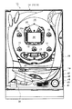
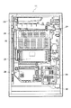
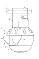
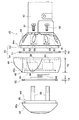
図1は、本発明の実施形態の遊技機としてのパチンコ機の正面図である。図2は、図1の背面図である。図3は、発射装置と発射ハンドルを設けてある受け皿ユニットを手前側斜め上方から見た皿ユニットの外観斜視図である。図4は、発射ハンドルの側面図である。図5は、発射ハンドルの分解側面図である。 FIG. 1 is a front view of a pachinko machine as a gaming machine according to an embodiment of the present invention. FIG. 2 is a rear view of FIG. FIG. 3 is an external perspective view of the saucer unit as seen from a diagonally upper side of the saucer unit provided with the launching device and the launching handle. FIG. 4 is a side view of the firing handle. FIG. 5 is an exploded side view of the firing handle.
図1に示すように、遊技機としてのパチンコ機11は、枠状の筐体12、遊技盤保持枠13、及び前面パネル14等で構成されている。遊技盤保持枠13は、遊技盤16を有して、筐体12に回転自在に設けてある。前面パネル14は、遊技盤保持枠13を開閉できるように、筐体12に回転自在に設けてある。前面パネル14は、遊技盤16を覆うガラスを有して遊技盤16を開閉するガラス枠18と、遊技球としてのパチンコ球を発射する発射装置31及びこの発射装置31を操作する発射ハンドル41を設けてある皿ユニット19とを有している。
As shown in FIG. 1, a
遊技盤16の前面には、液晶からなる特別図柄表示画面22を有するエスカッション20と、複数の入賞口15と、特別入賞口17と、どの入賞口にも入らなかったパチンコ球が遊技盤16から排出されるアウト口21と、不図示の障害釘等を設けてある。特別図柄表示画面22は、遊技盤16のほぼ中央に位置してエスカッション20の開口20aから露出するように設けてある。
On the front surface of the
図2に示すように、パチンコ機1の背面側には、島に設置してある貯留装置から一度に多数のパチンコ球が送り込まれても受け止めることのできる賞球タンク23と、賞球タンク23から流出する賞球を案内する横案内路24及び不図示の縦案内路と、表側に特別図柄表示画面22を備えた液晶ユニット25と、サブ制御基板26と、パチンコ機全体を制御する主制御基板27と、パチンコ機全体の電源となる電源ユニット28と、賞球の払い出し制御を行う払い出し制御基板29と、発射装置31を発射制御する発射制御基板30等を備えてある。
As shown in FIG. 2, on the back side of the pachinko machine 1, a
主制御基板27は、パチンコ機全体を制御するため、パチンコ機1の動作全体を管理するシステムプログラム及び遊技用の実行プログラムが予め記憶された半導体メモリ等からなる記憶部と、これらのプログラムを実行するマイクロプロセッサ(MPU)とを備えている。
In order to control the entire pachinko machine, the
次に、図3乃至図5に基づいて、発射ハンドル41を説明する。なお、図4、図5において左側から遊技者が発射ハンドル41を把持するので、図4、図5の左側を手前側、右側を奥側とする。
Next, the
発射ハンドル41は、皿ユニット19に固定された本体42と、本体42に取り付けられた指先接触片44と、指先接触片44に取り付けられた掌接片43と、指先接触片44と掌接片43とに両側から回転自在に支持された回転部材45と、指先接触片44と回転部材45との間に位置する隙間埋め部材としての第1隙間埋めリング51と、回転部材45と掌接片43との間に位置する隙間埋め部材としての第2隙間埋めリング52と、回転部材45と掌接片43との間に設けた付勢手段としての復帰ばね46等を備えている。
The
指先接触片44の手前側端部には、環状突部53を手前側に向けて突設してある。回転部材45の奥側端部には、環状突部53を受け入れる環状凹部54を形成してある。また、掌接片43の奥側端部には、環状突部55を奥側に向けて突設してある。回転部材45の手前側端部には、環状突部55を受け入れる環状凹部56を形成してある。なお、環状突部53と環状凹部54は、第1隙間埋めリング51を回転支持する回転支持部63を構成している。同様に、環状突部55と環状凹部56は、第2隙間埋めリング52を回転支持する回転支持部64を構成している。
An
第1隙間埋めリング51は、環状突部53の外周に装着されるようにリング状に形成されている。また、第2隙間埋めリング52も、環状突部55の外周に装着されるようにリング状に形成されている。
The first
以上の発射ハンドル41の各部品は、図5に示す位置関係において、ねじ57を、指先接触片44に形成した貫通孔58に挿入し、第1隙間埋めリング51、回転部材45の貫通孔59、第2隙間埋めリング52を貫通させて、掌接片43に突設してあるボス軸60にねじ込んで締め付けると、図4に示すように組み立てられる。
In the positional relationship shown in FIG. 5, the parts of the firing handle 41 described above are inserted into the through
発射ハンドル41が組み立てられると、ボス軸60の先端が指先接触片44のボス部61の凹部62に挿入されて凹部62の底に当接して、指先接触片44の手前側面44aと掌接片43の奥側面43aとの間隔が、第1隙間埋めリング51の厚みT1、回転部材45の厚みT2、第2隙間埋めリング52の厚みT3の合計寸法とほぼ同一になるようにしてあるので、回転部材45は1対の規制部材としての指先接触片44と掌接片43とにスラスト方向の移動を規制されて遊技者によって回転できるようになっている。
When the firing handle 41 is assembled, the tip of the
回転部材45は、環状突部53と環状凹部54との嵌合と、環状突部55と環状凹部56との嵌合とによって、指先接触片44と掌接片43とに支持されて回転するようになっている。回転部材45は、遊技者が回転しやすくするため、3つの第1乃至第3指掛け突起47,48,49を、指を受け入れ可能な間隔に回転外周面45aに設けてある。本体42、指先接触片44、回転部材45及び掌接片43はプラスチック成型品であるが、回転部材45は導電性材料、例えば金属材料で形成されている。
The
掌接片43及び回転部材45が金属材料で形成されているのは、発射ハンドル41に遊技者の手(体の一部)が触れたとき、発射ハンドル41がアースされて発射装置31が作動し、遊技者が発射ハンドル41から手を離したとき、発射装置31が自動的に停止するようにするためである。
The
第1隙間埋めリング51は、指先接触片44と回転部材45との隙間を埋めており、その隙間に挿入物(例えばコイン)をこじるようにして無理やり押し込もうとしても、挿入物が滑る摩擦係数を備えた材料、例えば樹脂材料で形成されている。第2隙間埋めリング52も、掌接片43と回転部材45との隙間を埋めており、その隙間に挿入物(例えばコイン)をこじるようにして無理やり押し込もうとしても、挿入物が滑る摩擦係数を備えた材料、例えば樹脂材料で形成されている。
The first
因みに、指先接触片44と回転部材45との隙間と、掌接片43と回転部材45との隙間は、夫々約0.5mm乃至2mmである。この隙間が、例えば、約2mmの場合、第1、第2隙間埋めリング51,52の厚みは、約1.5mmである。第1、第2隙間埋めリング51,52の厚みは、回転部材45の回転を阻害しない程度の厚みにしてあるのが好ましい。
Incidentally, the gap between the
仮に、第1、第2隙間埋めリング51,52で隙間をほぼ完全に埋めた場合には、この第1、第2隙間埋めリング51,52の摩擦係数は、約0.1乃至0.2に設定されているのが好ましい。 If the gap is almost completely filled with the first and second gap filling rings 51 and 52, the friction coefficient of the first and second gap filling rings 51 and 52 is about 0.1 to 0.2. Is preferably set.
復帰ばね46は、図1、図3において、回転部材45を左方向に回転付勢するようになっている。回転部材45は、復帰ばね46によって左方向に回転力を受けて、不図示のストッパによって、図3に示す回転開始位置に位置決めされるようになっている。
The return spring 46 is configured to urge the
以上の構成において、遊技者が皿ユニット19にパチンコ球を供給して、例えば、図3に示す発射ハンドル41の第1指掛け突起47の左側に右手の親指を掛け、第2、第3指掛け突起47,48の間に人差し指を掛け、第2、第3指掛け突起48,49の間に中指を掛け、第3指掛け突起49の右側に薬指、小指を掛けて、回転部材45を図3に示す矢印方向に回転させると、発射装置31が発射制御基板30の制御によってパチンコ球を遊技盤16に発射する。発射されたパチンコ球は、遊技盤16を転動落下して、いずれかの入賞口15,17に入球すると、パチンコ機11の背面に貯留してあるパチンコ球が、入賞口15,17に応じた数だけ皿ユニット19に賞球として供給される。パチンコ球が、どこの入賞口15,17にも入球しない場合、アウト口21からアウト球として排出される。
In the above configuration, the player supplies a pachinko ball to the
ところで、本実施形態の遊技機11は、遊技者が、指先接触片44と回転部材45との隙間、あるいは指先接触片44と回転部材45との隙間に、挿入物(例えばコイン)をこじるようにして無理やり押し込もうとしても、その隙間を第1、第2隙間埋めリングで埋めてあるので、挿入物が挿入されにくいとともに、滑ってほとんど挿入されることがないようになっている。
By the way, in the
また、第1、第2隙間埋めリング51,52の摩擦係数を挿入物が滑る摩擦係数に設定してあるので、同様に、挿入物が挿入されにくいとともに、滑ってほとんど挿入されることがないようになっている。仮に挿入物が、第1隙間埋めリング51と指先接触片44との間、第1隙間埋めリング51と回転部材45との間、第2隙間埋めリング52と回転部材45との間、及び第2隙間埋めリング52と掌接片43との間のいずれかの間に挿入されたとしても、第1、第2隙間埋めリング51,52の表面が滑り易くなっているので、その挿入物が滑り落ちて、遊技者に上記間に挿入物を挿入するのをあきらめさせ、発射ハンドルの損傷を防止することができる。
Further, since the friction coefficient of the first and second gap filling rings 51 and 52 is set to the friction coefficient with which the insert slides, similarly, the insert is difficult to insert and is hardly slipped. It is like that. Suppose that the insert is between the first
なお、隙間埋めリング51,52を設けたことによって回転部材45の回転が阻害されることが考えられるが、第1隙間埋めリング51の厚みT1を指先接触片44と回転部材45との隙間の寸法を超えない厚みにし、同様に、第2隙間埋めリング52の厚みT2を掌接片43と回転部材45との隙間の寸法を超えない厚みにすることによって、回転部材45の回転が阻害されることなく、遊技者が回転部材の最適な回転位置を容易に探し出すことができる。この場合、隙間埋めリング51,52の厚みは、挿入物を隙間に挿入しようとしても、挿入することのできない厚み以上であることは勿論である。
Although it is conceivable that the rotation of the rotating
また、隙間埋めリング51,52の厚みT1、T2を上記隙間以下の厚みにして、指先接触片44と回転部材45との少なくとも一方の表面を回転部材45の回転を許容する表面を回転部材45の回転を許容する表面にすることによって、回転部材45の回転が阻害されることがなくなる。同様に、掌接片43と回転部材45との少なくとも一方の表面を回転部材45の回転を許容する表面にすることによって、回転部材45の回転が阻害されることがなくなる。この結果、隙間埋めリング51,52を設けてあっても、遊技者が回転部材45の最適な回転位置を容易に探し出すことができる。なお、隙間埋めリング51,52の表面を摩擦係数約0.1乃至0.2に設定して滑りやすくしてあるのが好ましい。また、隙間埋めリング51,52の厚みは、挿入物を隙間挿入しようとしても、挿入することのできない厚み以上であることは勿論である。
Further, the thicknesses T1 and T2 of the gap filling rings 51 and 52 are set to be equal to or smaller than the above gap, and at least one surface of the
したがって、本実施形態の遊技機11は、遊技者によって発射ハンドル41に傷を付けられたり、発射ハンドル41の一部分を破損されたりするようなことが少なくなる。
Therefore, the
なお、指先接触片44と回転部材45との隙間と、指先接触片44と掌接片43との隙間とに隙間埋めリング51,52を設けてあるが、必ずしも、両方の隙間に設ける必要はない。いずれか一方の隙間に設けてあってもよい。
The gap filling rings 51 and 52 are provided in the gap between the
11 パチンコ機(遊技機)
16 遊技盤
30 発射制御基板
31 発射装置
41 発射ハンドル
42 本体
43 掌接片(規制部材)
44 指先接触片(規制部材)
45 回転部材
45a 回転外周面
46 復帰ばね
51 第1隙間埋めリング(隙間埋め部材)
52 第2隙間埋めリング(隙間埋め部材)
53 環状突部
54 環状凹部
55 環状突部
56 環状凹部
63 回転支持部
64 回転支持部
11 Pachinko machines (game machines)
16
44 Fingertip contact piece (regulating member)
45 Rotating
52 Second gap filling ring (gap filling member)
53
Claims (3)
前記遊技盤に遊技球を発射する発射装置と、
前記発射装置が遊技球を発射する勢いを回転角に基づいて制御可能な発射ハンドルと、を備えた遊技機において、
前記発射ハンドルが、前記発射装置が遊技球を発射する勢いを回転角に基づいて制御可能な回転部材と、前記回転部材がスラスト方向へ移動するのを前記回転部材の前記スラスト方向の両側から規制する1対の規制部材とを備え、
前記1対の規制部材の少なくとも一方の規制部材と前記回転部材との隙間に、該隙間を埋める隙間埋め部材を設け、
該隙間埋め部材が前記隙間に挿入物を挿入されるのを阻止することを特徴とする遊技機。 A game board having a game,
A launcher for launching a game ball onto the game board;
In a gaming machine comprising: a launching handle capable of controlling the momentum at which the launching device launches a game ball based on a rotation angle;
The firing handle restricts the rotating member capable of controlling the momentum of the launching device to launch the game ball based on the rotation angle, and the rotational member moving in the thrust direction from both sides in the thrust direction. And a pair of regulating members that
In the gap between at least one of the pair of regulating members and the rotating member, a gap filling member is provided to fill the gap,
A gaming machine, wherein the gap filling member prevents an insert from being inserted into the gap.
A rotation support portion that rotatably supports the rotation member is provided between the pair of regulating members, and the gap filling member is formed in a ring shape having a thickness less than the gap, and the rotation support portion The gaming machine according to claim 1, wherein the gaming machine is provided in the game machine.
Priority Applications (1)
| Application Number | Priority Date | Filing Date | Title |
|---|---|---|---|
| JP2004112050A JP2005296037A (en) | 2004-04-06 | 2004-04-06 | Game machine |
Applications Claiming Priority (1)
| Application Number | Priority Date | Filing Date | Title |
|---|---|---|---|
| JP2004112050A JP2005296037A (en) | 2004-04-06 | 2004-04-06 | Game machine |
Publications (1)
| Publication Number | Publication Date |
|---|---|
| JP2005296037A true JP2005296037A (en) | 2005-10-27 |
Family
ID=35328321
Family Applications (1)
| Application Number | Title | Priority Date | Filing Date |
|---|---|---|---|
| JP2004112050A Pending JP2005296037A (en) | 2004-04-06 | 2004-04-06 | Game machine |
Country Status (1)
| Country | Link |
|---|---|
| JP (1) | JP2005296037A (en) |
Cited By (1)
| Publication number | Priority date | Publication date | Assignee | Title |
|---|---|---|---|---|
| JP2008279198A (en) * | 2007-05-14 | 2008-11-20 | Mrd:Kk | Operating handle for game machine |
Citations (2)
| Publication number | Priority date | Publication date | Assignee | Title |
|---|---|---|---|---|
| JPH10258154A (en) * | 1997-03-18 | 1998-09-29 | Daiichi Shokai Co Ltd | Pachinko machine handle device |
| JP2003225380A (en) * | 2002-02-05 | 2003-08-12 | Fuji Shoji:Kk | Ball game machine |
-
2004
- 2004-04-06 JP JP2004112050A patent/JP2005296037A/en active Pending
Patent Citations (2)
| Publication number | Priority date | Publication date | Assignee | Title |
|---|---|---|---|---|
| JPH10258154A (en) * | 1997-03-18 | 1998-09-29 | Daiichi Shokai Co Ltd | Pachinko machine handle device |
| JP2003225380A (en) * | 2002-02-05 | 2003-08-12 | Fuji Shoji:Kk | Ball game machine |
Cited By (1)
| Publication number | Priority date | Publication date | Assignee | Title |
|---|---|---|---|---|
| JP2008279198A (en) * | 2007-05-14 | 2008-11-20 | Mrd:Kk | Operating handle for game machine |
Similar Documents
| Publication | Publication Date | Title |
|---|---|---|
| JP3853229B2 (en) | Game machine door structure | |
| JP5970976B2 (en) | Game machine | |
| JP6019808B2 (en) | Game machine | |
| JP2003325899A (en) | Game machine | |
| JP6019806B2 (en) | Game machine | |
| JP2005296037A (en) | Game machine | |
| JP5171052B2 (en) | Game machine | |
| JPH08299540A (en) | Wheel device for pachinko machine | |
| JP2005296038A (en) | Game machine | |
| JP2007236871A (en) | Game machine | |
| JP6019807B2 (en) | Game machine | |
| JP2009279129A (en) | Game machine | |
| JP2942470B2 (en) | Ball game machine operation handle | |
| JP2005296039A (en) | Game machine | |
| JP4897614B2 (en) | Game machine | |
| JP3602461B2 (en) | Game ball launch control device | |
| JP2002113167A (en) | Game ball shooting handle | |
| JP3936207B2 (en) | Game machine door structure | |
| JP4730741B2 (en) | Game machine | |
| JP6528830B2 (en) | Gaming machine | |
| JP5360710B2 (en) | Pachinko machine | |
| JP4226545B2 (en) | Pachinko machine | |
| JP2018167107A (en) | Game machine | |
| JP2010082250A (en) | Frame structure and game machine | |
| JP2018167106A (en) | Game machine |
Legal Events
| Date | Code | Title | Description |
|---|---|---|---|
| A621 | Written request for application examination |
Effective date: 20070405 Free format text: JAPANESE INTERMEDIATE CODE: A621 |
|
| RD02 | Notification of acceptance of power of attorney |
Effective date: 20070627 Free format text: JAPANESE INTERMEDIATE CODE: A7422 |
|
| A977 | Report on retrieval |
Free format text: JAPANESE INTERMEDIATE CODE: A971007 Effective date: 20100106 |
|
| A131 | Notification of reasons for refusal |
Free format text: JAPANESE INTERMEDIATE CODE: A131 Effective date: 20100112 |
|
| A02 | Decision of refusal |
Free format text: JAPANESE INTERMEDIATE CODE: A02 Effective date: 20100601 |
|
| RD04 | Notification of resignation of power of attorney |
Effective date: 20100716 Free format text: JAPANESE INTERMEDIATE CODE: A7424 |