JP2005296517A - Headrest device - Google Patents
Headrest device Download PDFInfo
- Publication number
- JP2005296517A JP2005296517A JP2004120648A JP2004120648A JP2005296517A JP 2005296517 A JP2005296517 A JP 2005296517A JP 2004120648 A JP2004120648 A JP 2004120648A JP 2004120648 A JP2004120648 A JP 2004120648A JP 2005296517 A JP2005296517 A JP 2005296517A
- Authority
- JP
- Japan
- Prior art keywords
- headrest
- lock tooth
- stay
- lock
- seat back
- Prior art date
- Legal status (The legal status is an assumption and is not a legal conclusion. Google has not performed a legal analysis and makes no representation as to the accuracy of the status listed.)
- Pending
Links
Images


Landscapes
- Chair Legs, Seat Parts, And Backrests (AREA)
Abstract
【課題】簡単な構造で、かつ、調節操作を容易に行えるヘッドレスト装置の提供を図る。
【解決手段】ロック溝6がロックツース11から外れる車両前方に向けてヘッドレスト4をねじりコイルスプリング12Aのばね力に抗して回動して、所要の上下調節位置で回動力を解除すれば、ヘッドレスト4がねじりコイルスプリング12Aにより元の回転方向位置へ回動復元し、その高さ位置に適合したロック溝6がロックツース11に係合してヘッドレスト位置が確定される。
【選択図】図1To provide a headrest device having a simple structure and capable of easily performing an adjusting operation.
If the headrest 4 is rotated against the spring force of a torsion coil spring 12A toward the front of the vehicle where the lock groove 6 is disengaged from the lock tooth 11 and the rotational force is released at a required vertical adjustment position, the headrest 4 is restored to its original rotational position by the torsion coil spring 12A, and the lock groove 6 adapted to the height position is engaged with the lock tooth 11 to determine the headrest position.
[Selection] Figure 1
Description
本発明は、自動車用シート等に用いられるヘッドレスト装置に関する。 The present invention relates to a headrest device used for an automobile seat or the like.
自動車用シートに用いられているヘッドレストは、周知のように着座乗員の頭部位置に合わせて上下位置調節自在に配設されており、中でも、シートバック側部に設けたノブの回動操作により、シートバック内部に配索したケーブルを介してヘッドレストを昇降作動させるようにしたものが知られている(特許文献1参照)。
前記従来のヘッドレスト装置では、シートバック内部にヘッドレストの昇降ガイド機構と、ケーブルおよびプーリー等の昇降操作力伝達機構を設ける一方、シートバック側部に設けられるノブにはヘッドレスト位置を規定するためのブレーキ機構(ロック機構)を設けてあるため、構造が複雑化してコスト的に不利となってしまうことは否めない。 In the conventional headrest device, a headrest lifting guide mechanism and a lifting operation force transmission mechanism such as a cable and a pulley are provided inside the seatback, while a knob provided on the side portion of the seatback is used to define a headrest position. Since the mechanism (lock mechanism) is provided, it cannot be denied that the structure becomes complicated and disadvantageous in terms of cost.
そこで、本発明は簡単な構造で、かつ、調節操作を容易に行うことができるヘッドレスト装置を提供するものである。 Accordingly, the present invention provides a headrest device that has a simple structure and can be easily adjusted.
本発明にあっては、ヘッドレストの底面に突設され、上下方向に複数の係合部を多段状に設けたヘッドレストスティと、
シートバックフレームのアッパフレームに前後方向に回動自在に設けられて、前記ヘッドレストスティを上下方向に摺動自在に嵌挿,保持する筒状のスティホルダと、
シートバックフレームに設けられ、前記ヘッドレストスティの係合部の1つに係合して、ヘッドレストの上下方向位置を規定するロックツースと、
これら係合部とロックツースとが係合するように前記ヘッドレストをスティホルダの回転方向に付勢する付勢手段と、を備えたことを最も主要な特徴とする。
In the present invention, a headrest stay that protrudes from the bottom surface of the headrest and has a plurality of engagement portions in a vertical direction,
A cylindrical sticker that is provided on the upper frame of the seat back frame so as to be pivotable in the front-rear direction, and that fits and holds the headrest stick slidably in the vertical direction;
A lock tooth that is provided on a seat back frame and engages with one of the engaging portions of the headrest stay to define a vertical position of the headrest;
The main feature is that it includes urging means for urging the headrest in the rotation direction of the sticker so that the engagement portion and the lock tooth are engaged with each other.
本発明によれば、ヘッドレストの上下位置調節に際しては、係合部がロックツースから外れる方向にヘッドレストを付勢手段の付勢力に抗して回動して、所要の上下調節位置で回動力を解除すれば、該ヘッドレストが付勢手段により元の回転方向位置へ回動復元し、その高さ位置に適合した係合部がロックツースに係合してヘッドレスト位置が確定される。 According to the present invention, when adjusting the vertical position of the headrest, the headrest is rotated against the urging force of the urging means in the direction in which the engaging portion is disengaged from the lock tooth, and the rotational force is released at the required vertical adjustment position. Then, the headrest is rotated and restored to the original rotational direction position by the urging means, and the engaging portion adapted to the height position is engaged with the lock tooth to determine the headrest position.
従って、乗員はヘッドレストを、一方向に回動しつつ上下方向に移動調節するだけで容易に位置調節することができ、しかも、スティホルダをアッパフレームに対して前後方向に回動自在とし、かつ、係合部がロックツースに対して係合する方向にヘッドレストを回動付勢する付勢手段を付設するだけの簡単な構造とすることができて、部品点数が少なくコスト的に有利に得ることができる。 Therefore, the occupant can easily adjust the position of the headrest by simply moving and adjusting the headrest in the vertical direction while rotating in one direction, and the stay holder can be rotated in the front-rear direction with respect to the upper frame. It is possible to obtain a simple structure in which the urging means for urging and urging the headrest in the direction in which the engaging portion engages with the lock tooth can be provided, and the number of parts can be reduced and the cost can be advantageously obtained. Can do.
以下、本発明の実施形態を図面と共に詳述する。 Hereinafter, embodiments of the present invention will be described in detail with reference to the drawings.
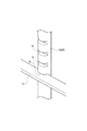
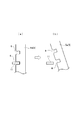
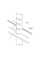
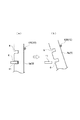
図1〜図5は本発明のヘッドレスト装置の第1実施形態を示し、図1はシートバックフレームとヘッドレストスティとの組付状態を示す斜視図、図2は図1のA部の拡大斜視図、図3は図1のB部の拡大斜視図、図4はヘッドレストを回動した状態を示す図1と同様の斜視図、図5は係合部とロックツースの係合状態を(a)に係合部とロックツースの係合解除状態を(b)にそれぞれ示す側面図である。 1 to 5 show a first embodiment of a headrest device according to the present invention, FIG. 1 is a perspective view showing an assembled state of a seat back frame and a headrest stay, and FIG. 2 is an enlarged perspective view of a portion A in FIG. 3 is an enlarged perspective view of a portion B in FIG. 1, FIG. 4 is a perspective view similar to FIG. 1 showing a state in which the headrest is rotated, and FIG. 5 is an engagement state of the engagement portion and the lock tooth (a). It is a side view which shows the engagement release state of an engaging part and a lock tooth in (b), respectively.
この第1実施形態のヘッドレスト装置は、図1に示すようにシートバックフレーム1は左右一対の板材からなるサイドフレーム2と、これらサイドフレーム2の上端部間に跨って接合配置した丸棒材からなる正面門型のアッパフレーム3とを備えている。
In the headrest device according to the first embodiment, as shown in FIG. 1, the seat back frame 1 is composed of a
ヘッドレスト4には、丸棒材を正面門型に曲折成形して、両側脚部5aをヘッドレスト4の底面から突出させたヘッドレストスティ5を設けてあり、このヘッドレストスティ5の両側脚部5aの車両前面側には、係合部としてのほぼ水平な複数のロック溝6を所要の等間隔をおいて上下方向に多段状に設けてある。
The headrest 4 is provided with a headrest stay 5 in which a round bar is bent into a front gate shape, and both
一方、前記シートバックフレーム1のアッパフレーム3の上辺部3aには左右一対の円筒状のスティホルダ7を前後方向に回動自在に設けてあり、これらスティホルダ7に前記ヘッドレストスティ5の脚部5aを上下方向に摺動自在に嵌挿,保持してある。
On the other hand, a pair of left and right
このスティホルダ7は、円筒状のブラケット8aを前記アッパフレーム3の上辺部3aの所定位置で前後方向に回動自在に嵌装して取付けた金属製の円筒状のホルダーベース8と、上端に鍔部9aを形成すると共に下端に係止スナップ部9bを形成した樹脂材からなる円筒状のホルダー本体9とを備え、該ホルダー本体10をホルダーベース8の上方より圧入し、スナップ部10bをホルダーベース8をくぐり抜けさせてその下縁に係止することにより組付けて構成してある。
The
また、アッパフレーム3の前記左右のサイドフレーム2の上端部に接合した両側辺部3bに跨って、金属製の角棒材からなるロックツース11を接合配置して、図3に示すように該ロックツース11が前記ヘッドレストスティ5の両側脚部5aの前側でロック溝6の1つに係合して、ヘッドレスト4の上下方向位置を規定するようにしてある。
Further, a
更に、前記アッパフレーム3の上辺部3aには、図2に示すように一方のスティホルダ7に近接して付勢手段12を配設して、該付勢手段12により前記ロック溝6とロックツース11とが係合するように前記ヘッドレスト4をスティホルダ7の回転方向に付勢している。
Further, as shown in FIG. 2, an
本実施形態では付勢手段12としてねじりコイルスプリング12Aが用いられ、該ねじりコイルスプリング12Aを前記上辺部3aに嵌装配置して、一端を上辺部3aに設けた係止爪3a’に係止すると共に、他端をホルダーベース8のブラケット8aに設けた係止爪8a’に係止することにより、ヘッドレスト4を車両後方に回動付勢し、ヘッドレストスティ5の脚部5aを車両前面側に押し出してロック溝6をロックツース11に係合させてある。
In this embodiment, a
以上の構成によりこの第1実施形態によれば、ヘッドレスト4の上下位置調節に際しては、ヘッドレスト4を図1の矢印aに示すようにねじりコイルスプリング12Aのばね力に抗して若干前方へ回動すると、ヘッドレストスティ5のロック溝6が図5の(a)に示すロックツース11と係合している状態から、(b)に示すようにロックツース11から離脱して係合解除される。そこで、図4の矢印bに示すようにヘッドレスト4を所要の高さ位置まで上下調節して、その位置でヘッドレスト4の回動力を解除すれば、該ヘッドレスト4がねじりコイルスプリング12Aのばね力で元の回転方向位置へ回動復元し、その高さ位置に適合したロック溝6がロックツース11に係合してヘッドレスト位置が確定される。
With the above configuration, according to the first embodiment, when the vertical position of the headrest 4 is adjusted, the headrest 4 is rotated slightly forward against the spring force of the
従って、乗員はヘッドレスト4を、前方向に回動しつつ上下方向に移動調節するだけで位置調節することができて、調節操作を容易に行うことができる。 Accordingly, the occupant can adjust the position of the headrest 4 simply by moving and adjusting the headrest 4 in the vertical direction while rotating in the forward direction, and can easily perform the adjustment operation.
また、スティホルダ7をアッパフレーム3の上辺部3aに対して前後方向に回動自在とし、かつ、ロック溝6がロックツース11に対して係合する方向にヘッドレスト4を回動付勢するねじりコイルスプリング12Aを付設するだけの簡単な構造とすることができるから、部品点数が少なくコスト的に有利に得ることができる。
Further, the torsion coil for rotating the
更に、本実施形態では前述のようにねじりコイルスプリング12Aによりヘッドレスト4を車両後方に回動付勢し、ヘッドレストスティ5の脚部5aを車両前面側に押し出してロック溝6をロックツース11に係合させるようにしてあるので、乗員頭部からヘッドレスト4に後方への入力が作用しても、これらロック溝6とロックツース11とが噛み合う方向への入力となって、ヘッドレスト4による乗員頭部の拘束性に支障を来すことはない。
Further, in the present embodiment, as described above, the headrest 4 is pivotally biased rearward by the
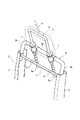
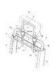
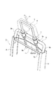
図6〜図9は本発明の第2実施形態を示し、前記第1実施形態と同一部分に同一符号を付して重複する説明を省略して述べるものとし、図6はシートバックフレームとヘッドレストスティとの組付状態を示す斜視図、図7は図6のC部の拡大斜視図、図8はヘッドレストを回動した状態を示す図6と同様の斜視図、図8は係合部とロックツースの係合状態を(a)に係合部とロックツースの係合解除状態を(b)にそれぞれ示す側面図である。 6 to 9 show a second embodiment of the present invention, in which the same parts as those in the first embodiment are denoted by the same reference numerals and redundant description is omitted, and FIG. 6 shows a seat back frame and a headrest. FIG. 7 is an enlarged perspective view of a portion C in FIG. 6, FIG. 8 is a perspective view similar to FIG. 6 showing a state in which the headrest is rotated, and FIG. It is a side view which shows the engagement state of a lock tooth in (a), and the engagement part and the engagement release state of a lock tooth in (b), respectively.
この第2実施形態は付勢手段12の変形例を示すもので、付勢手段12としてヘッドレストスティ5の両側脚部5aを車両前方へ向けて押圧するワイヤや帯状板ばね等の弾性体が用いられ、本実施形態ではワイヤ12Bを用いた例を示している。
This second embodiment shows a modification of the
ワイヤ12Bはスティホルダ7とロックツース11との上下方向間で、ヘッドレストスティ5の両側脚部5aの背面に弾接するように、左右のサイドフレーム2の上端部間に跨って緊張状態で接合配置してある。
The
従って、この第2実施形態ではワイヤ12Bの弾性力によって前記脚部5aが車両前方に押動され、図6,図7および図9(a)に示すようにロック溝6がその前方のロックツース11に係合して、ヘッドレスト4の高さ位置を規定している。
Therefore, in the second embodiment, the
ヘッドレスト4の上下位置調節に際しては、図6の矢印aに示すようにヘッドレスト4を前方へ回動すると、前記脚部5aによってワイヤ12Bが図8に示すように後方へ撓んで図9(b)に示すようにロック溝6がロックツース11から離脱して係合解除するから、図8の矢印bに示すようにヘッドレスト4を上下方向に移動調節すれば、前記脚部5aがワイヤ12Bに対して滑動し、任意の調節位置でヘッドレスト4の回動力を解除することにより、ワイヤ12Bの弾性力で脚部5aが車両前方へ押動され、ヘッドレスト4が元の回動方向位置に回動復元して、その調節高さ位置に適合したロック溝6がロックツース11に係合して、該ヘッドレスト4の調節高さが確定する。
When adjusting the vertical position of the headrest 4, when the headrest 4 is rotated forward as indicated by an arrow a in FIG. 6, the
従って、この第2実施形態にあっても前記第1実施形態と同様の効果を得ることができる。 Therefore, even in the second embodiment, the same effect as in the first embodiment can be obtained.
ところで、本発明のヘッドレスト装置を第1,第2実施形態に例をとって説明したが、これら実施形態に限ることなく本発明の要旨を逸脱しない範囲で他の実施形態を各種採用することができる。 By the way, although the headrest device of the present invention has been described by taking the first and second embodiments as examples, it is possible to adopt various other embodiments without departing from the gist of the present invention without being limited to these embodiments. it can.
1 シートバックフレーム
2 サイドフレーム
3 アッパフレーム
4 ヘッドレスト
5 ヘッドレストスティ
6 ロック溝(係合部)
7 スティホルダ
11 ロックツース
12 付勢手段
DESCRIPTION OF SYMBOLS 1 Seat back
7
Claims (2)
シートバックフレームのアッパフレームに前後方向に回動自在に設けられて、前記ヘッドレストスティを上下方向に摺動自在に嵌挿,保持する筒状のスティホルダと、
シートバックフレームに設けられ、前記ヘッドレストスティの係合部の1つに係合して、ヘッドレストの上下方向位置を規定するロックツースと、
これら係合部とロックツースとが係合するように前記ヘッドレストをスティホルダの回転方向に付勢する付勢手段と、を備えたことを特徴とするヘッドレスト装置。 A headrest stay protruding from the bottom surface of the headrest and having a plurality of engaging portions in a vertical direction;
A cylindrical sticker that is provided on the upper frame of the seat back frame so as to be pivotable in the front-rear direction, and that fits and holds the headrest stick slidably in the vertical direction;
A lock tooth that is provided on a seat back frame and engages with one of the engaging portions of the headrest stay to define a vertical position of the headrest;
An urging means for urging the headrest in the rotation direction of the sticker so that the engagement portion and the lock tooth are engaged with each other.
Priority Applications (1)
| Application Number | Priority Date | Filing Date | Title |
|---|---|---|---|
| JP2004120648A JP2005296517A (en) | 2004-04-15 | 2004-04-15 | Headrest device |
Applications Claiming Priority (1)
| Application Number | Priority Date | Filing Date | Title |
|---|---|---|---|
| JP2004120648A JP2005296517A (en) | 2004-04-15 | 2004-04-15 | Headrest device |
Publications (1)
| Publication Number | Publication Date |
|---|---|
| JP2005296517A true JP2005296517A (en) | 2005-10-27 |
Family
ID=35328759
Family Applications (1)
| Application Number | Title | Priority Date | Filing Date |
|---|---|---|---|
| JP2004120648A Pending JP2005296517A (en) | 2004-04-15 | 2004-04-15 | Headrest device |
Country Status (1)
| Country | Link |
|---|---|
| JP (1) | JP2005296517A (en) |
Cited By (3)
| Publication number | Priority date | Publication date | Assignee | Title |
|---|---|---|---|---|
| JP2007135629A (en) * | 2005-11-14 | 2007-06-07 | Okamura Corp | Headrest device of chair |
| CN103976836A (en) * | 2014-05-10 | 2014-08-13 | 朱劲荣 | Tenon-mortise structure position control bracket of sickbed pillow |
| CN103976835A (en) * | 2014-05-10 | 2014-08-13 | 朱劲荣 | Sickbed pillow single-tenon multi-mortise hanging rack |
-
2004
- 2004-04-15 JP JP2004120648A patent/JP2005296517A/en active Pending
Cited By (5)
| Publication number | Priority date | Publication date | Assignee | Title |
|---|---|---|---|---|
| JP2007135629A (en) * | 2005-11-14 | 2007-06-07 | Okamura Corp | Headrest device of chair |
| CN103976836A (en) * | 2014-05-10 | 2014-08-13 | 朱劲荣 | Tenon-mortise structure position control bracket of sickbed pillow |
| CN103976835A (en) * | 2014-05-10 | 2014-08-13 | 朱劲荣 | Sickbed pillow single-tenon multi-mortise hanging rack |
| CN103976835B (en) * | 2014-05-10 | 2017-01-25 | 朱劲荣 | Sickbed pillow single-tenon multi-mortise hanging rack |
| CN103976836B (en) * | 2014-05-10 | 2017-01-25 | 朱劲荣 | Tenon-mortise structure position control bracket of sickbed pillow |
Similar Documents
| Publication | Publication Date | Title |
|---|---|---|
| EP1777101B1 (en) | Automobile seat | |
| US20120261964A1 (en) | Vehicle seat | |
| KR101274451B1 (en) | Headrest for vehicle | |
| JP2002144938A (en) | Headrest device | |
| US9789789B2 (en) | Vehicular seat | |
| US9061615B2 (en) | Folding headrest | |
| JP5119946B2 (en) | Armrest structure of vehicle seat | |
| JP5313480B2 (en) | Tilt mechanism built-in suspension mechanism | |
| JP2003127741A (en) | Vehicle seat structure | |
| JP2005296517A (en) | Headrest device | |
| US20080185883A1 (en) | Automobile seat | |
| KR101593849B1 (en) | Apparatus for sliding in headrest | |
| JP2001163101A (en) | Headrest structure of vehicle seat | |
| KR100559464B1 (en) | Reclining device for car seat | |
| JP2000052825A (en) | Seat with flip-up headrest | |
| JP2018083451A (en) | Vehicle seat | |
| JP2009234504A (en) | Seat sliding device for vehicle | |
| JP6643713B2 (en) | Vehicle seat reclining device | |
| JP3776749B2 (en) | Chair | |
| JP2013001177A (en) | Vehicle seat | |
| JPH11115571A (en) | Seat slide device | |
| JP2015112975A (en) | Forward inclining type headrest | |
| JP3743554B2 (en) | Automotive seat device | |
| KR20090118219A (en) | Horizontal movement support of headrest for car seat | |
| JP5572327B2 (en) | Sheet device |