JP2005297029A - Laser beam machine - Google Patents
Laser beam machine Download PDFInfo
- Publication number
- JP2005297029A JP2005297029A JP2004118483A JP2004118483A JP2005297029A JP 2005297029 A JP2005297029 A JP 2005297029A JP 2004118483 A JP2004118483 A JP 2004118483A JP 2004118483 A JP2004118483 A JP 2004118483A JP 2005297029 A JP2005297029 A JP 2005297029A
- Authority
- JP
- Japan
- Prior art keywords
- light
- laser
- opening
- light guide
- disposed
- Prior art date
- Legal status (The legal status is an assumption and is not a legal conclusion. Google has not performed a legal analysis and makes no representation as to the accuracy of the status listed.)
- Granted
Links
Images
Landscapes
- Laser Beam Processing (AREA)
Abstract
Description
本発明は、レーザ加工ヘッドを移動させながらワークにレーザ加工を施すレーザ加工機に関する。 The present invention relates to a laser processing machine that performs laser processing on a workpiece while moving a laser processing head.
従来、レーザ加工ヘッドを移動させながらワークにレーザ加工を施すレーザ加工機としては、種々の構造のものが提案されている(例えば、特許文献1参照)。 2. Description of the Related Art Conventionally, various structures have been proposed as laser processing machines that perform laser processing on a workpiece while moving a laser processing head (see, for example, Patent Document 1).
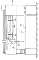
図6は、そのようなレーザ加工機の従来構造の一例を示す正面図であり、図中の符号200は、レーザ光を発生させるレーザ発振器を示し、符号201は、ワークWを載置する加工テーブルを示し、符号202は、移動駆動されながら該ワークWにレーザ光を照射するレーザ加工ヘッドを示し、符号203は、レーザ発振器200とレーザ加工ヘッド202との間のレーザ光路系を示し、符号204は、レーザ光路系を密閉して埃等の侵入を防止するための蛇腹部材を示す。
FIG. 6 is a front view showing an example of a conventional structure of such a laser processing machine.
ところで、上述した蛇腹部材204は、レーザ加工ヘッド202の矢印205の方向への往復移動に伴い繰り返し伸縮されることとなるため、破損され易く耐久性に劣るという問題があった。
By the way, the
本発明は、耐久性に優れたレーザ加工機を提供することを目的とするものである。 An object of this invention is to provide the laser processing machine excellent in durability.
請求項1に係る発明は、図1及び図2に例示するものであって、レーザ光を発生させるレーザ光発生手段(2)と、該レーザ光のための光路を形成する光路手段(A)と、該光路手段(A)を通過してきたレーザ光をワーク(W)に照射するレーザ加工ヘッド(3)と、を備えたレーザ加工機(1)において、
前記光路手段(A)は、
レーザ光(L1)を一の方向(30)に導く空洞部(31a)、及び該空洞部(31a)の開口部(31b)を有する導光部(31)と、
前記レーザ加工ヘッド(3)が移動駆動されることに伴い前記開口部(31b)に沿って移動され、前記空洞部(31a)からレーザ光を他の方向(32)に取り出して前記レーザ加工ヘッド(3)に供給する光取り出し部(33)と、
前記光取り出し部(33)が配置された部分以外(30B)では前記開口部(31b)を閉塞するように配置され、前記光取り出し部(33)が配置された部分(30A)では前記開口部(31b)を閉塞せずに前記光取り出し部(33)を迂回するように配置されて前記光取り出し部(33)へのレーザ光の取り出しを許容するベルト部材(36)と、を有し、
該ベルト部材(36)及び前記導光部(31)の少なくとも一方に磁石(図5(a) (b) の符号37参照)が配置されていて、該ベルト部材(36)が前記磁石の磁力により前記開口部(31b)を閉塞することを特徴とする。
The invention according to
The optical path means (A)
A light guide (31) having a cavity (31a) for guiding laser light (L1) in one direction (30), and an opening (31b) of the cavity (31a);
As the laser processing head (3) is driven to move, the laser processing head is moved along the opening (31b), and the laser beam is extracted from the cavity (31a) in the other direction (32). A light extraction section (33) to be supplied to (3);
Other than the portion where the light extraction portion (33) is disposed (30B), the opening portion (31b) is disposed so as to be closed, and the portion (30A) where the light extraction portion (33) is disposed is the opening portion. A belt member (36) disposed so as to bypass the light extraction portion (33) without blocking (31b) and allowing extraction of laser light to the light extraction portion (33);
A magnet (see
請求項2に係る発明は、図1に例示するものであって、請求項1に係る発明において、前記開口部(31b)を通って前記導光部(31)の内部に突出するように前記光取り出し部(33)に設けられたブラケット(35)と、該ブラケット(35)に取り付けられて前記空洞部(31a)に配置された光反射手段(34)と、を設け、
前記空洞部(31a)からのレーザ光の取り出しは、該レーザ光(L1)を前記光反射手段(34)にて反射させることにより行う、ことを特徴とする。
The invention according to claim 2 is illustrated in FIG. 1, and in the invention according to
The extraction of the laser light from the cavity (31a) is performed by reflecting the laser light (L1) by the light reflecting means (34).
請求項3に係る発明は、請求項1又は2に係る発明において、前記光取り出し部(33)は、
該光取り出し部(33)の移動方向一端部であって前記開口部(31b)に近接する位置に配置された第1ローラ(331)と、
前記移動方向中央部であって前記開口部(31b)から離れた位置に配置された第2ローラ(332)と、
前記移動方向他端部であって前記開口部(31b)に近接する位置に配置された第3ローラ(333)と、を有し、
前記ベルト部材(36)は、前記第1ローラ(331)及び前記導光部(31)の間、前記第2ローラ(332)の外側、並びに前記第3ローラ(333)及び前記導光部(31)の間をそれぞれ通るように配置された、ことを特徴とする。
The invention according to claim 3 is the invention according to
A first roller (331) disposed at a position close to the opening (31b) at one end in the moving direction of the light extraction portion (33);
A second roller (332) disposed in a central portion in the moving direction and away from the opening (31b);
A third roller (333) disposed at a position adjacent to the opening (31b) at the other end in the moving direction;
The belt member (36) includes the first roller (331) and the light guide (31), the outside of the second roller (332), and the third roller (333) and the light guide ( 31) are arranged so as to pass through each of them.
請求項4に係る発明は、図3に例示するものであって、請求項1乃至3のいずれか1項に記載の発明において、前記開口部(31b)の両縁に沿うように前記磁石(37)が配置され、前記ベルト部材(36)がスチールベルトであって、該ベルト部材(36)が前記磁石(37)の磁力を介して前記開口部(31b)を閉塞することを特徴とする。
The invention according to claim 4 is illustrated in FIG. 3, and in the invention according to any one of
請求項5に係る発明は、図4に例示するものであって、請求項1乃至4のいずれか1項に記載の発明において、前記導光部(31)はレール部材(40a,40a)を有し、
前記光取り出し部(33)は前記レール部材(40a,40a)に沿って移動するように構成された、ことを特徴とする。
The invention according to claim 5 is illustrated in FIG. 4, and in the invention according to any one of
The light extraction part (33) is configured to move along the rail members (40a, 40a).
請求項6に係る発明は、図2に例示するものであって、請求項1乃至5のいずれか1項に記載の発明において、ワーク(W)を載置する加工テーブル(T)と、該加工テーブル(T)の上方に横架されると共に前記レーザ加工ヘッド(3)を移動自在に支持するクロスアーム(50)と、を備え、
前記導光部(31)が前記加工テーブル(T)に沿うように配置され、
前記光取り出し部(33)が前記クロスアーム(50)に取り付けられて、
前記レーザ光発生手段(2)からのレーザ光が、前記導光部(31)、前記光取り出し部(33)及び前記クロスアーム(50)に導かれた後、前記レーザ加工ヘッド(3)に供給される、ことを特徴とする。
The invention according to claim 6 is illustrated in FIG. 2, and in the invention according to any one of
The light guide (31) is arranged along the processing table (T),
The light extraction part (33) is attached to the cross arm (50),
After the laser light from the laser light generating means (2) is guided to the light guide part (31), the light extraction part (33) and the cross arm (50), it is applied to the laser processing head (3). Supplied.
請求項7に係る発明は、請求項1乃至6のいずれか1項に記載の発明において、ワーク(W)を載置する加工テーブル(T)と、該加工テーブル(T)の上方に横架されて前記レーザ加工ヘッド(3)を移動自在に支持するクロスアーム(50)と、を備え、
前記導光部(31)が前記クロスアーム(50)に沿って配置され、
前記光取り出し部(33)が前記レーザ加工ヘッド(3)に取り付けられて、
前記レーザ光発生手段(2)からのレーザ光が、前記導光部(31)及び前記光取り出し部(33)を経由して前記レーザ加工ヘッド(3)に供給される、ことを特徴とする。
The invention according to
The light guide (31) is disposed along the cross arm (50);
The light extraction part (33) is attached to the laser processing head (3),
The laser beam from the laser beam generating means (2) is supplied to the laser processing head (3) via the light guide (31) and the light extraction unit (33). .
なお、括弧内の番号などは、図面における対応する要素を示す便宜的なものであり、従って、本記述は図面上の記載に限定拘束されるものではない。 Note that the numbers in parentheses are for the sake of convenience indicating the corresponding elements in the drawings, and therefore the present description is not limited to the descriptions on the drawings.
請求項1、及び4〜7に係る発明によれば、ベルト部材は導光部に密着した状態で開口部を閉塞するので、導光部内部への埃や異物の侵入を防止することができる。また、前記光取り出し部を前記一の方向(又はその反対方向)に移動させた場合、ベルト部材はその厚み方向に移動されるだけなので傷みにくく、蛇腹を用いる場合に比べて耐久性が向上される。別の言い方をすれば、ベルト部材は、軸方向に大きく変形される蛇腹と異なり、変形量は小さいので、変形し易い材料にて形成する必要は必ずしもなく、その他の性質を持つ材料(例えば、耐久性や耐熱性に富む材料)を用いることができる。
According to the inventions according to
請求項2に係る発明によれば、前記光反射手段と前記光取り出し部とは一体的に移動されるように構成されているため、前記光反射手段を駆動する手段を別途設けておく必要は無く、構造を簡素化できる。また、前記光反射手段と前記光取り出し部との相対位置関係は常に適正に維持されるため、該光反射手段からレーザ加工ヘッドにレーザ光を正確に導くことができる。 According to the invention of claim 2, since the light reflecting means and the light extraction portion are configured to be moved integrally, it is necessary to separately provide a means for driving the light reflecting means. And the structure can be simplified. Further, since the relative positional relationship between the light reflecting means and the light extraction portion is always properly maintained, the laser light can be accurately guided from the light reflecting means to the laser processing head.
請求項3に係る発明によれば、光取り出し部が如何なる位置に移動したとしても、レーザ光の光路をベルト部材が遮蔽してしまうことはなく、導光部から光取り出し部へのレーザ光の取り込みが可能になる。 According to the third aspect of the invention, the belt member does not block the optical path of the laser light regardless of the position of the light extraction portion, and the laser light from the light guide portion to the light extraction portion is not blocked. Capture is possible.
以下、図1乃至図5に沿って、本発明を実施するための最良の形態について説明する。 Hereinafter, the best mode for carrying out the present invention will be described with reference to FIGS. 1 to 5.
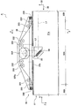
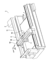
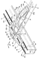
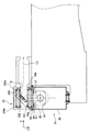
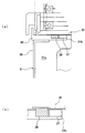
図1は、図3のE−E断面図であって、光取り出し部等の構造を示す断面図である。また、図2は、本発明に係るレーザ加工機の全体構造の一例を示す外観斜視図であり、図3は、光路手段の構造の一例を示す斜視図であり、図4は、図1のF−F断面図であり、図5(a) は、図4の詳細断面図であり、図5(b) は、その詳細拡大断面図である。 FIG. 1 is a cross-sectional view taken along the line E-E in FIG. 3, illustrating a structure of a light extraction portion and the like. 2 is an external perspective view showing an example of the overall structure of the laser beam machine according to the present invention, FIG. 3 is a perspective view showing an example of the structure of the optical path means, and FIG. FIG. 5 (a) is a detailed sectional view of FIG. 4, and FIG. 5 (b) is a detailed enlarged sectional view thereof.
本発明に係るレーザ加工機は、図2に符号1で示すように、レーザ光を発生させるレーザ光発生手段2と、該レーザ光のための光路を形成する光路手段Aと、該光路手段Aを通過してきたレーザ光をワークWに照射するレーザ加工ヘッド3と、を備えている。
As shown by
ところで、前記光路手段Aは、図1に示すように、レーザ光L1を一の方向30に導く導光部31と、該レーザ光L1を、符号L2に示すように他の方向32に取り出して前記レーザ加工ヘッド3に供給する光取り出し部33と、を有している。このうち、導光部31は、レーザ光L1の光路として機能する空洞部31aを内部に有しており、表面には該空洞部31aの開口部31b(図3参照)を有している。
By the way, the optical path means A, as shown in FIG. 1, takes out the laser light L1 in one
ところで、上述したレーザ加工ヘッド3は少なくとも前記一の方向30に沿って移動駆動可能に構成されている。また、前記導光部31の空洞部31a及び開口部31bは前記一の方向30に沿って形成されていて、前記光取り出し部33は、前記一の方向30に移動駆動され、いずれの位置においても前記空洞部31aからレーザ光L1を取り出せるようになっている(詳細は後述する)。
By the way, the laser processing head 3 described above is configured to be movable and movable along at least the one
前記光取り出し部33は、前記導光部31と接した状態又は微小間隙を開けた状態で移動させると良い。例えば、図4に示すように、レール部材40a,40aを導光部31に(前記一の方向30に沿うように)配置しておいて、該レール部材40a,40aに前記光取り出し部33を移動自在に支持させておき、不図示の駆動手段によって該光取り出し部33を前記レール部材40a,40aに沿って移動駆動すると良い。この場合、前記光取り出し部33が前記レール部材40a,40aを摺動するようにしても、前記光取り出し部33に不図示のローラを設けておいて該ローラがレール部材上を転動するようにしても良い。
The
ところで、光取り出し部33がいずれの位置にある場合にもレーザ光L1を取り出せるようにするには、図1に示すように、該レーザ光L1を符号L2で示すように反射させるための光反射手段34を前記空洞部31aの内部(正確には、レーザ光L1の光路上)であって前記光取り出し部33に対向する位置に配置しておくと良い。この図1では、前記開口部31bを通って前記導光部31の空洞部31aに突出するようなブラケット35が前記光取り出し部33に取り付けられていて、光反射手段34はそのブラケット35に取り付けられているので、光反射手段34は、前記光取り出し部33と一体的にレーザ光L1の光路上を移動することとなるため、前記光反射手段34を駆動する手段を別途設けておく必要は無く、構造を簡素化できる。また、前記光反射手段34と前記光取り出し部33との相対位置関係は常に適正に維持されるため、該光反射手段34からレーザ加工ヘッド3にレーザ光を正確に導くことができる。なお、構造及び駆動制御が複雑になるが、光反射手段34を光取り出し部33に取り付けないで、両者を別の駆動手段で駆動するようにしても良い。
By the way, in order to be able to extract the laser beam L1 regardless of the position of the
ところで、上述した導光部31には、その開口部31bに沿うようにベルト部材36が配置されている。このベルト部材36は、前記光取り出し部33が配置された部分(つまり、図1に符号30Aで示す部分)では前記開口部31bを閉塞せず(前記光取り出し部33を迂回するように配置されて)、前記光取り出し部33へのレーザ光の取り出しを阻害しないようになっている(詳細は後述する)。また、該ベルト部材36は、前記光取り出し部33が配置された部分以外(図1に符号30Bで示す部分)では前記開口部31bを閉塞して、導光部内部への埃や異物の侵入を防止するように構成されている。本発明によれば、光取り出し部33を前記一の方向30(又はその反対方向)に移動させた場合、ベルト部材36はその厚み方向(図1に符号32で示す方向、及びその反対方向)に移動されるだけなので傷みにくく、蛇腹を用いる場合に比べて耐久性が向上される。なお、“ベルト部材36が迂回するように配置され”とは、ベルト部材36が導光部31(開口部31b)から離れた状態に配置されて、ベルト部材36と導光部31との間に光路(図4の符号L3参照)を形成できることを意味する。
By the way, the
上述したベルト部材36は磁力により開口部31bを閉塞するようにすると良い。例えば、図5(a) (b) に示すように、開口部31bの端縁(好ましくは、開口部31bの両方の端縁)に沿って磁石37を配置し、前記ベルト部材36はスチールベルトにすると良い。このようにした場合には、ベルト部材36は導光部31に密着した状態で開口部31bを閉塞するので、導光部内部への埃や異物の侵入を防止することができる。なお、磁石は、前記ベルト部材36及び前記導光部31の少なくとも一方に設けていれば良く、
(1) 上述のように導光部31の側に設けても、
(2) 導光部31の側でなくベルト部材36の側に設けても、
(3) 導光部31及びベルト部材36の両方に設けても、
いずれでも良い。ところで、上記(2) のように、磁石をベルト部材36の側に設ける方法としては、
(2-1) ベルト部材36に磁石を埋め込む方法
(2-2) ベルト部材36に磁石を接着する方法
(2-3) ベルト部材36に帯状ゴム磁石を用いる方法
を挙げることができる。なお、磁石を前記ベルト部材36の側に配置する場合は、前記光取り出し部33の一端部(後述するように第1ローラ331が配置される部分)及び他端部(後述するように第3ローラ333が配置される部分)にも光取り出し部側磁石を配置しておいて(該光取り出し部側磁石をベルト部材35と開口部31bとの間に配置する場合には、ベルト部材35の側の磁石と同極性の磁石、光取り出し部側磁石と開口部31bとの間にベルト部材35を配置する場合には、ベルト部材35の側の磁石とは異極性の磁石)、光取り出し部33を移動させる際には、ベルト部材側磁石及び光取り出し部側磁石の反発力又は吸引力によって、ベルト部材36を前記導光部31から容易に剥離できるようにしておくと良い。
The
(1) Even if it is provided on the
(2) Even if it is provided on the side of the
(3) Even if provided on both the
Either is fine. By the way, as described in (2) above, as a method of providing the magnet on the
(2-1) Method of embedding magnet in
(2-2) Method of adhering magnet to belt
(2-3) A method of using a belt-like rubber magnet for the
ところで、導光部31を形成する部材は、図3及び図4に詳示するように断面が略コ字状のものとし、開口部31bは上側に配置すると良い。
By the way, the member forming the
また、前記開口部31bの両縁に沿うように、前記一の方向30にウレタン等のシール部材(図3及び図5(a) (b) の符号38参照)を設けておいて、該シール部材38と前記ベルト部材36と密着させて、導光部内部への埃や異物の侵入を防止すると良い。この場合、図5(a) (b) に示すように、シール部材38と磁石37とを互いに近接するように配置しておいて、磁石37により引き付けられたベルト部材36がシール部材38に押し付けられ密着されるようにしておくと良い。また、図5(b) に示すように、シール部材38の表面を、磁石37の表面よりも突出させておいて、磁石37がシール部材38に接触し易くすると良い。この場合のシール部材38は、ベルト部材36に押し付けられて多少弾性変形する程度の材質にすると良く、ベルト部材36も多少撓む程度の材質にすると良い。図5(a) (b)では、シール部材38は磁石37の片側のみに配置されているが、磁石37の両側に配置しても良い。
Further, a seal member such as urethane (see
なお、図5(a) (b)に示すシール部材38や磁石37は、空洞部31aを形成する部材(符号39で示す部材)自体に形成されておらず板状の部材40に形成されているが、部材39自体に形成しても良い。
5 (a) and 5 (b) are not formed on the member (the member denoted by reference numeral 39) forming the
ところで、ベルト部材36は、前記光取り出し部33へのレーザ光L2の取り出しを阻害しないように前記光取り出し部33を迂回させる必要があるが、そのために最適な光取り出し部33の構造について図1を参照して説明する。
By the way, the
図示の光取り出し部33は、回転自在な第1〜第3ローラ331,332,333を有している。このうち、第1ローラ331は、該光取り出し部33の移動方向一端部であって前記開口部31bに近接する位置に配置され、第2ローラ332は、前記移動方向中央部であって前記開口部31bから離れた位置に配置され、第3ローラ333は、前記移動方向他端部であって前記開口部31bに近接する位置に配置されている。また、この第2ローラ332と開口部31bとの間には反射ミラー334を配置して、導光部31からのレーザ光L2をレーザ加工ヘッド3の側(例えば、紙面垂直方向)に反射するように構成している。さらに、前記ベルト部材36は、前記第1ローラ331及び前記導光部31の間(つまり、前記第1ローラ331及び前記開口部31bの間)、前記第2ローラ332の外側(前記導光部31が配置された方とは反対側)、並びに前記第3ローラ333及び前記導光部31の間(つまり、前記第3ローラ333及び前記開口部31bの間)をそれぞれ通るように配置されている。このように構成した場合、光取り出し部33が前記一の方向30の如何なる位置に移動したとしても、レーザ光L2の光路をベルト部材36が遮蔽してしまうことはなく、導光部31から光取り出し部33へのレーザ光L2の取り込みが可能となる。なお、ベルト部材36が導光部31から離間した位置に配置される部分30Aでは、図3に示すように、ローラ331,332,333を回転自在に支持する壁部335a,335bが立設されていて、ベルト部材36と協働することにより開口部31bを閉塞するため、導光部内部への埃や異物の侵入を確実に防止することができる。但し、一方の壁部335a(レーザ加工ヘッド3に近接する方の壁部)には、図4に示すように、孔部Gが形成されているので、反射ミラー334にて反射されたレーザ光L2が遮蔽されることは無い。また、図1に示すように、移動方向端部のローラ331,333よりも外側には、可撓性材料からなるへら部材336を配置し、ベルト部材36の表面の埃や異物を除去できるようにしておくと良い。
The illustrated
ところで、本発明に係るレーザ加工機には、図2に示すように、ワークWを載置する加工テーブルTを設けておくと良い。そして、この加工テーブルTの上方にはクロスアーム50を横架し、このクロスアーム50には、前記レーザ加工ヘッド3を移動自在に支持させると良い。このようなレーザ加工機において、上述した導光部31は、前記加工テーブルTに沿うような位置(図2の符号51参照)に配置すると良く、上述した光取り出し部33は前記クロスアーム50に取り付けておいて(図2の符号52参照)、前記レーザ光発生手段2からのレーザ光が、符号51に示す位置に配置された前記導光部31、符号52に示す位置に配置された前記光取り出し部33、及び前記クロスアーム50に導かれた後、前記レーザ加工ヘッド3に供給されるようにしておくと良い。
By the way, the laser beam machine according to the present invention is preferably provided with a machining table T on which the workpiece W is placed as shown in FIG. A
また、上述のように、加工テーブルTやクロスアーム50を配置するが、導光部31は、前記加工テーブルTに沿うように配置するのではなく、前記クロスアーム50に沿うように配置し、光取り出し部33は前記レーザ加工ヘッド3に取り付けておいて(図2の符号53参照)、前記レーザ光発生手段2からのレーザ光が、前記クロスアーム50に沿うように配置された前記導光部31、及び符号53に示す位置に配置された前記光取り出し部33を経由して前記レーザ加工ヘッド3に供給されるようにしておくと良い。
Further, as described above, the processing table T and the
さらに、図2及び図3に示すように、符号51で示す位置、及びクロスアーム50に沿う位置の両方に導光部31を配置し、符号52で示す位置、及び符号53で示す位置の両方に光取り出し部33を配置しても良い。
Further, as shown in FIGS. 2 and 3, the
1 レーザ加工機
2 レーザ発生手段
3 レーザ加工ヘッド
31 導光部
31a 空洞部
31b 開口部
33 光取り出し部
34 光反射手段
35 ブラケット
36 ベルト部材
37 磁石
331 第1ローラ
332 第2ローラ
333 第3ローラ
A 光路手段
T 加工テーブル
W ワーク
DESCRIPTION OF
Claims (7)
前記光路手段は、
レーザ光を一の方向に導く空洞部、及び該空洞部の開口部を有する導光部と、
前記レーザ加工ヘッドが移動駆動されることに伴い前記開口部に沿って移動され、前記空洞部からレーザ光を他の方向に取り出して前記レーザ加工ヘッドに供給する光取り出し部と、
前記光取り出し部が配置された部分以外では前記開口部を閉塞するように配置され、前記光取り出し部が配置された部分では前記開口部を閉塞せずに前記光取り出し部を迂回するように配置されて前記光取り出し部へのレーザ光の取り出しを許容するベルト部材と、を有し、
該ベルト部材及び前記導光部の少なくとも一方に磁石が配置されていて、該ベルト部材が前記磁石の磁力により前記開口部を閉塞する、
ことを特徴とするレーザ加工機。 Laser processing machine comprising: laser light generating means for generating laser light; optical path means for forming an optical path for the laser light; and a laser processing head for irradiating a workpiece with laser light that has passed through the optical path means In
The optical path means is
A cavity for guiding laser light in one direction, and a light guide having an opening of the cavity;
A light extraction portion that is moved along the opening as the laser processing head is driven to move, extracts laser light from the cavity in another direction, and supplies the laser processing head to the laser processing head;
Arranged so as to close the opening except for the portion where the light extraction portion is disposed, and bypasses the light extraction portion without blocking the opening at the portion where the light extraction portion is disposed. And a belt member that allows extraction of the laser light to the light extraction unit,
A magnet is disposed on at least one of the belt member and the light guide, and the belt member closes the opening by the magnetic force of the magnet;
A laser processing machine characterized by that.
前記空洞部からのレーザ光の取り出しは、該レーザ光を前記光反射手段にて反射させることにより行う、
ことを特徴とする請求項1に記載のレーザ加工機。 A bracket provided in the light extraction portion so as to protrude into the light guide portion through the opening, and a light reflecting means attached to the bracket and disposed in the cavity portion;
The extraction of the laser beam from the cavity is performed by reflecting the laser beam with the light reflecting means.
The laser beam machine according to claim 1.
該光取り出し部の移動方向一端部であって前記開口部に近接する位置に配置された第1ローラと、
前記移動方向中央部であって前記開口部から離れた位置に配置された第2ローラと、
前記移動方向他端部であって前記開口部に近接する位置に配置された第3ローラと、を有し、
前記ベルト部材は、前記第1ローラ及び前記導光部の間、前記第2ローラの外側、並びに前記第3ローラ及び前記導光部の間をそれぞれ通るように配置された、
ことを特徴とする請求項1又は2に記載のレーザ加工機。 The light extraction unit is
A first roller disposed at a position close to the opening at one end in the moving direction of the light extraction unit;
A second roller disposed at a position at the center in the moving direction and away from the opening;
A third roller disposed at a position close to the opening at the other end in the moving direction,
The belt member is disposed so as to pass between the first roller and the light guide unit, on the outside of the second roller, and between the third roller and the light guide unit, respectively.
The laser processing machine according to claim 1 or 2, wherein
ことを特徴とする請求項1乃至3のいずれか1項に記載のレーザ加工機。 The magnet is disposed along both edges of the opening, the belt member is a steel belt, and the belt member closes the opening through the magnetic force of the magnet.
The laser beam machine according to any one of claims 1 to 3, wherein:
前記光取り出し部は前記レール部材に沿って移動するように構成された、ことを特徴とする請求項1乃至4のいずれか1項に記載のレーザ加工機。 The light guide has a rail member,
The laser beam machine according to claim 1, wherein the light extraction unit is configured to move along the rail member.
前記導光部が前記加工テーブルに沿うように配置され、
前記光取り出し部が前記クロスアームに取り付けられて、
前記レーザ光発生手段からのレーザ光が、前記導光部、前記光取り出し部及び前記クロスアームに導かれた後、前記レーザ加工ヘッドに供給される、
ことを特徴とする請求項1乃至5のいずれか1項に記載のレーザ加工機。 A processing table for placing a workpiece; and a cross arm that is horizontally mounted above the processing table and movably supports the laser processing head;
The light guide is arranged along the processing table,
The light extraction part is attached to the cross arm,
After the laser light from the laser light generating means is guided to the light guide unit, the light extraction unit, and the cross arm, it is supplied to the laser processing head.
The laser beam machine according to any one of claims 1 to 5, wherein:
前記導光部が前記クロスアームに沿って配置され、
前記光取り出し部が前記レーザ加工ヘッドに取り付けられて、
前記レーザ光発生手段からのレーザ光が、前記導光部及び前記光取り出し部を経由して前記レーザ加工ヘッドに供給される、
ことを特徴とする請求項1乃至6のいずれか1項に記載のレーザ加工機。
A processing table for placing a workpiece; and a cross arm that is horizontally mounted above the processing table and movably supports the laser processing head;
The light guide is disposed along the cross arm;
The light extraction part is attached to the laser processing head,
Laser light from the laser light generating means is supplied to the laser processing head via the light guide unit and the light extraction unit.
The laser beam machine according to any one of claims 1 to 6, wherein:
Priority Applications (1)
| Application Number | Priority Date | Filing Date | Title |
|---|---|---|---|
| JP2004118483A JP4676161B2 (en) | 2004-04-14 | 2004-04-14 | Laser processing machine |
Applications Claiming Priority (1)
| Application Number | Priority Date | Filing Date | Title |
|---|---|---|---|
| JP2004118483A JP4676161B2 (en) | 2004-04-14 | 2004-04-14 | Laser processing machine |
Publications (2)
| Publication Number | Publication Date |
|---|---|
| JP2005297029A true JP2005297029A (en) | 2005-10-27 |
| JP4676161B2 JP4676161B2 (en) | 2011-04-27 |
Family
ID=35329206
Family Applications (1)
| Application Number | Title | Priority Date | Filing Date |
|---|---|---|---|
| JP2004118483A Expired - Fee Related JP4676161B2 (en) | 2004-04-14 | 2004-04-14 | Laser processing machine |
Country Status (1)
| Country | Link |
|---|---|
| JP (1) | JP4676161B2 (en) |
Cited By (2)
| Publication number | Priority date | Publication date | Assignee | Title |
|---|---|---|---|---|
| JP2007118057A (en) * | 2005-10-31 | 2007-05-17 | Yamazaki Mazak Corp | Laser processing machine optical path system dustproof device |
| US7323656B2 (en) | 2005-10-26 | 2008-01-29 | Yamazaki Mazak Corporation | Seal device of light path system in laser beam machine |
Citations (8)
| Publication number | Priority date | Publication date | Assignee | Title |
|---|---|---|---|---|
| JPS6256287U (en) * | 1985-09-25 | 1987-04-07 | ||
| JPS632582A (en) * | 1986-06-19 | 1988-01-07 | Shibuya Kogyo Co Ltd | Closing device for opening part allowing movement of focus head |
| JPS6310094A (en) * | 1986-06-30 | 1988-01-16 | Mitsubishi Electric Corp | Laser beam machine |
| JPS6363595A (en) * | 1986-09-02 | 1988-03-19 | Mitsubishi Electric Corp | Laser light transmission device |
| JPH01245991A (en) * | 1988-03-29 | 1989-10-02 | Haitekuno:Kk | Laser beam cutting device |
| JPH02284787A (en) * | 1989-03-20 | 1990-11-22 | Yefim P Sukhman | Laser material processor and laser treatment method of workpiece using said processor |
| JP2000233292A (en) * | 1999-02-10 | 2000-08-29 | Mitsubishi Electric Corp | Laser processing machine |
| JP2005103596A (en) * | 2003-09-30 | 2005-04-21 | Amada Co Ltd | Sealing mechanism |
-
2004
- 2004-04-14 JP JP2004118483A patent/JP4676161B2/en not_active Expired - Fee Related
Patent Citations (8)
| Publication number | Priority date | Publication date | Assignee | Title |
|---|---|---|---|---|
| JPS6256287U (en) * | 1985-09-25 | 1987-04-07 | ||
| JPS632582A (en) * | 1986-06-19 | 1988-01-07 | Shibuya Kogyo Co Ltd | Closing device for opening part allowing movement of focus head |
| JPS6310094A (en) * | 1986-06-30 | 1988-01-16 | Mitsubishi Electric Corp | Laser beam machine |
| JPS6363595A (en) * | 1986-09-02 | 1988-03-19 | Mitsubishi Electric Corp | Laser light transmission device |
| JPH01245991A (en) * | 1988-03-29 | 1989-10-02 | Haitekuno:Kk | Laser beam cutting device |
| JPH02284787A (en) * | 1989-03-20 | 1990-11-22 | Yefim P Sukhman | Laser material processor and laser treatment method of workpiece using said processor |
| JP2000233292A (en) * | 1999-02-10 | 2000-08-29 | Mitsubishi Electric Corp | Laser processing machine |
| JP2005103596A (en) * | 2003-09-30 | 2005-04-21 | Amada Co Ltd | Sealing mechanism |
Cited By (3)
| Publication number | Priority date | Publication date | Assignee | Title |
|---|---|---|---|---|
| US7323656B2 (en) | 2005-10-26 | 2008-01-29 | Yamazaki Mazak Corporation | Seal device of light path system in laser beam machine |
| JP2007118057A (en) * | 2005-10-31 | 2007-05-17 | Yamazaki Mazak Corp | Laser processing machine optical path system dustproof device |
| US7273999B2 (en) | 2005-10-31 | 2007-09-25 | Yamazaki Mazak Corporation | Dustproof device of light path system in laser beam machine |
Also Published As
| Publication number | Publication date |
|---|---|
| JP4676161B2 (en) | 2011-04-27 |
Similar Documents
| Publication | Publication Date | Title |
|---|---|---|
| JP2010091109A (en) | Coupling structure of sealing band in rectilinear robot | |
| JP4676161B2 (en) | Laser processing machine | |
| EP1566235B1 (en) | Laser beam working machine with first and second beam guide portions for shortening the length of the optical path, the latter being held constant during laser processing | |
| KR102402362B1 (en) | Transport apparatus, exposure apparatus and transport method | |
| MXPA04001304A (en) | Tool and method for opening a hem flange. | |
| JPWO2007145072A1 (en) | Support device | |
| JP6422182B2 (en) | Laser processing equipment | |
| JP2011125877A (en) | Laser beam machining method and apparatus | |
| JP6792728B2 (en) | Laser blanking device | |
| JP2007276044A (en) | Telescopic cover | |
| ITTO970202A1 (en) | LASER CUTTING SHEET METAL EQUIPMENT | |
| JP5133709B2 (en) | Laser repair device | |
| CA2527465A1 (en) | Bill processing apparatus | |
| JP2010188424A (en) | Laser beam machine | |
| JP5311176B2 (en) | Laser processing equipment | |
| JP2008242346A (en) | Transfer head of laser transfer device | |
| JP2006006086A (en) | Linear motor | |
| JP2006159272A (en) | Automatic beam mode-selection device of laser beam machine | |
| JPH10225786A (en) | Laser machining device | |
| JP2007030016A (en) | Laser beam machine | |
| JP2005210391A (en) | Image reading device | |
| JP4559269B2 (en) | Electronic component mounting device | |
| EP1779959A1 (en) | Seal device of light path system in laser beam machine | |
| US7273999B2 (en) | Dustproof device of light path system in laser beam machine | |
| JP2000337377A (en) | Stage equipment |
Legal Events
| Date | Code | Title | Description |
|---|---|---|---|
| A621 | Written request for application examination |
Free format text: JAPANESE INTERMEDIATE CODE: A621 Effective date: 20070306 |
|
| A977 | Report on retrieval |
Free format text: JAPANESE INTERMEDIATE CODE: A971007 Effective date: 20090618 |
|
| A131 | Notification of reasons for refusal |
Free format text: JAPANESE INTERMEDIATE CODE: A131 Effective date: 20100608 |
|
| A521 | Request for written amendment filed |
Free format text: JAPANESE INTERMEDIATE CODE: A523 Effective date: 20100716 |
|
| TRDD | Decision of grant or rejection written | ||
| A01 | Written decision to grant a patent or to grant a registration (utility model) |
Free format text: JAPANESE INTERMEDIATE CODE: A01 Effective date: 20110125 |
|
| A01 | Written decision to grant a patent or to grant a registration (utility model) |
Free format text: JAPANESE INTERMEDIATE CODE: A01 |
|
| A61 | First payment of annual fees (during grant procedure) |
Free format text: JAPANESE INTERMEDIATE CODE: A61 Effective date: 20110127 |
|
| FPAY | Renewal fee payment (event date is renewal date of database) |
Free format text: PAYMENT UNTIL: 20140204 Year of fee payment: 3 |
|
| R150 | Certificate of patent or registration of utility model |
Ref document number: 4676161 Country of ref document: JP Free format text: JAPANESE INTERMEDIATE CODE: R150 |
|
| R250 | Receipt of annual fees |
Free format text: JAPANESE INTERMEDIATE CODE: R250 |
|
| R250 | Receipt of annual fees |
Free format text: JAPANESE INTERMEDIATE CODE: R250 |
|
| R250 | Receipt of annual fees |
Free format text: JAPANESE INTERMEDIATE CODE: R250 |
|
| R250 | Receipt of annual fees |
Free format text: JAPANESE INTERMEDIATE CODE: R250 |
|
| R250 | Receipt of annual fees |
Free format text: JAPANESE INTERMEDIATE CODE: R250 |
|
| R250 | Receipt of annual fees |
Free format text: JAPANESE INTERMEDIATE CODE: R250 |
|
| R250 | Receipt of annual fees |
Free format text: JAPANESE INTERMEDIATE CODE: R250 |
|
| R250 | Receipt of annual fees |
Free format text: JAPANESE INTERMEDIATE CODE: R250 |
|
| R250 | Receipt of annual fees |
Free format text: JAPANESE INTERMEDIATE CODE: R250 |
|
| R250 | Receipt of annual fees |
Free format text: JAPANESE INTERMEDIATE CODE: R250 |
|
| LAPS | Cancellation because of no payment of annual fees |