JP2005297846A - Occupant protecting device of vehicle - Google Patents
Occupant protecting device of vehicle Download PDFInfo
- Publication number
- JP2005297846A JP2005297846A JP2004118990A JP2004118990A JP2005297846A JP 2005297846 A JP2005297846 A JP 2005297846A JP 2004118990 A JP2004118990 A JP 2004118990A JP 2004118990 A JP2004118990 A JP 2004118990A JP 2005297846 A JP2005297846 A JP 2005297846A
- Authority
- JP
- Japan
- Prior art keywords
- seat
- rollover
- airbag
- roll
- level
- Prior art date
- Legal status (The legal status is an assumption and is not a legal conclusion. Google has not performed a legal analysis and makes no representation as to the accuracy of the status listed.)
- Granted
Links
Images


Landscapes
- Automotive Seat Belt Assembly (AREA)
- Air Bags (AREA)
Abstract
Description
この発明は、車両の横転から乗員を保護する装置に関する。 The present invention relates to an apparatus for protecting an occupant from a vehicle rollover.
車両の旋回時において、車体のロール角またはロール角速度が大きくなると、エンジン回転を低減させる制御やブレーキを作動させる制御により、車両が横転に至るのを未然に防止するようにしたものが開示される(特許文献1)。コンテナキャリアの乗員保護装置であるが、運転室において、乗員を包囲するようなレイアウトに複数のエアバックが配置され、車体の傾きの程度に基づいて、車両の横転不可避を判定すると、これらエアバックを膨らませることにより、横転時の衝撃から乗員を保護するクッションとして機能させるようにしたものが開示される(特許文献2)。
特許文献2(横転から乗員を保護する装置)の場合、車両の横転不可避を判定すると、複数のエアバックを膨らませるため、横転後に乗員を包囲するエアバックにより、乗員が身動き取れないような不具合が考えられる。従来から乗員の保護にシートベルトが使用されるが、車高が大きく運転室の位置が高い、トラックなど商用車の座席においては、乗員の上体が垂直に立つ着座姿勢となり、シートベルトによると、乗員の座席への束縛も前後方向の移動量をよく抑えられるものの、乗員の横方向への移動量は十分に抑えられない。そのため、横転時に乗員の体がシートベルトから擦り抜け、座席から横転方向へ投げ出されかねないのである。シートベルトがプリテンショナル式の場合、プリテンショナは前からの衝撃をセンサが感知するとガスを発生させてその膨張力によりシートベルトの弛み分を瞬時に巻き取るようになっているが、横からの衝撃をセンサが感知しづらく、車両の横転時にプリテンショナが効かない可能性も考えられる。 In the case of Patent Document 2 (device that protects an occupant from overturning), if it is determined that the inversion of the vehicle is inevitable, a plurality of airbags are inflated, so that the occupant cannot move due to the airbag surrounding the occupant after the rollover Can be considered. Traditionally, seat belts have been used to protect passengers, but in the seats of commercial vehicles such as trucks where the height of the vehicle is large and the position of the cab is high, the upper body of the passenger is seated vertically, The amount of movement of the occupant in the lateral direction cannot be sufficiently suppressed, although the amount of movement of the occupant in the front-rear direction can be well suppressed. As a result, the occupant's body may rub through the seat belt and roll out from the seat in the rollover direction. When the seat belt is a pretensional type, the pretensioner generates gas when the sensor detects the impact from the front, and the expansion force instantly winds up the slack of the seat belt. There is a possibility that the pretensioner does not work when the vehicle rolls over, because it is difficult for the sensor to detect the impact.
この発明は、1種の保護手段のみによるのでなく、数種の保護手段を同時的に効かせたり、乗員の保護を徐々に高めるべく順次に効かせたり、車体のロール状態に応じてこれら保護手段の制御パターンを変えることにより、横転から乗員を適確に保護しえるシステムの提供を目的とする。 This invention is not only based on one type of protective means, but also several types of protective means can be applied simultaneously, or in order to gradually increase the protection of the occupant, or depending on the roll condition of the vehicle body. An object is to provide a system capable of appropriately protecting an occupant from rollover by changing a control pattern of means.
第1の発明は、車両の横転から乗員を保護する装置において、車体のロール角およびロール角速度を検出する手段と、ロール角速度が横転不可避レベル以上のときは、シートベルトのプリテンショナ、座席の両側に装備されるエアバックの少なくとも横転方向の前側に位置するエアバック、座席の前方に装備されるエアバック、を同時的に作動させるべく制御する手段と、ロール角速度が横転不可避レベル未満のときは、ロール角に基づいて、シートベルトのプリテンショナ、座席の両側に装備されるエアバックの少なくとも横転方向の前側に位置するエアバック、座席の前方に装備されるエアバック、を順次に作動させるべく制御する手段と、を備えることを特徴とする。 According to a first aspect of the present invention, there is provided a device for protecting an occupant from a rollover of a vehicle, a means for detecting a roll angle and a roll angular velocity of a vehicle body, and a seat belt pretensioner and both sides of a seat when the roll angular velocity is equal to or higher than a roll inevitable level. When the roll angular velocity is less than the inevitable rollover means, the airbag positioned at least in front of the airbag in the rollover direction, the airbag installed in front of the seat, and the roll angular velocity are controlled to operate simultaneously. Based on the roll angle, the seat belt pretensioner, the airbag provided at least in the rollover direction of the airbag provided on both sides of the seat, and the airbag provided in front of the seat are sequentially operated. And means for controlling.
第2の発明は、第1の発明に係る車両の乗員保護装置において、ロール角速度が横転不可避レベル未満のときは、ロール角に基づいて、シートベルトのプリテンショナ、座席の両側に装備されるエアバックの少なくとも横転方向の前側に位置するエアバック、座席の前方に装備されるエアバック、を順次に作動させるべく制御する手段については、ロール角が第1の判定レベル以上の継続状態が所定時間に及ぶとシートベルトのプリテンショナを作動させる手段と、ロール角が第2の判定レベル以上の継続状態が所定時間に及ぶと横転方向の前側に位置するパワーウインドの閉側操作手段を作動させる手段、ロール角が第3の判定レベル以上の継続状態が所定時間に及ぶと座席の両側に装備されるエアバックの少なくとも横転方向の前側に位置するエアバックを作動させる手段と、そのエアバックの作動から所定時間が経過すると座席の前方に装備されるエアバックを作動させる手段と、を備えることを特徴とする。 According to a second aspect of the present invention, in the vehicle occupant protection device according to the first aspect of the invention, when the roll angular velocity is less than the inevitable rollover level, the seat belt pretensioner and the air installed on both sides of the seat are based on the roll angle. With respect to the means for controlling the airbag positioned at least in front of the rollover direction and the airbag installed in front of the seat in order, the continuation state where the roll angle is equal to or higher than the first determination level is a predetermined time. Means for actuating the seat belt pretensioner, and means for actuating the closing operation means for the power window located on the front side in the rollover direction when the roll angle exceeds the second determination level for a predetermined time. When the continuation state where the roll angle is equal to or higher than the third judgment level reaches a predetermined time, it is positioned at least on the front side in the rollover direction of the airbag installed on both sides of the seat. Means for actuating the air bag which is characterized in that it comprises the the air bag predetermined time from the actuation of has passed and means for actuating the air bag to be mounted to the front of the seat, the.
第3の発明は、第1の発明に係る車両の乗員保護装置において、座席の両側に装備されるエアバックおよび座席の前方に装備されるエアバックは、ガス抜き孔を持たないことを特徴とする。 According to a third aspect of the present invention, in the vehicle occupant protection device according to the first aspect, the airbag provided on both sides of the seat and the airbag provided in front of the seat do not have a vent hole. To do.
第4の発明は、第1の発明に係る車両の乗員保護装置において、座席の前方に装備されるエアバックは、ガス抜き孔を塞ぐ栓と、座席の近くに配置される解除スイッチのONによりガス抜き孔の栓を開ける手段と、を備えることを特徴とする。 According to a fourth aspect of the present invention, in the vehicle occupant protection device according to the first aspect of the present invention, the airbag installed in front of the seat is provided by a plug that closes the vent hole and an ON of a release switch disposed near the seat. And means for opening a plug of the gas vent hole.
第5の発明は、第1の発明に係る車両の乗員保護装置において、ロール角が注意喚起レベル以上になるとその間は横転に対する注意喚起情報を発生する手段と、を備えることを特徴とする。 According to a fifth aspect of the present invention, in the vehicle occupant protection device according to the first aspect of the present invention, the vehicle occupant protection device includes means for generating alert information for rollover during the roll angle when the roll angle reaches or exceeds the alert level.
第1の発明においては、ロール角速度が横転不可避レベル未満のときは、ロール角が大きくなるに連れて、シートベルトのプリテンショナ,座席の両側に装備されるエアバックのうち少なくとも横転方向の前側のエアバック,座席の前方に装備されるエアバック、の順に効かせられる。シートベルトのプリテンショナが作動すると、シートベルトの弛み分が瞬時に巻き取られるようになり、座席への乗員の束縛が強化され、横方向への乗員の移動量も最小限に抑えられる。横転方向の前側に位置するエアバックが作動すると、膨らむエアバックが横転時の衝撃から乗員を保護するクッションとなる。座席の前方に位置するエアバックが作動すると、エアバックが乗員の前方空間に膨らみ、乗員を保護するクッションとなるのである。これらの保護手段が順次に作動することにより、乗員に一時に大きな負担を掛けることなく、横転時に乗員の適確な保護状態が得られる。その一方、ロール角速度が急に大きくなり、横転不可避レベル以上になると、これら保護手段を順次に作動させる余裕はないので、既に作動状態にある保護手段を含めてこれら全部を同時的に作動させることになる。このため、ロール角度の変化が急なロール状態においても、横転に遅れることなく、乗員の適確な保護状態が得られるのである。 In the first aspect of the invention, when the roll angular velocity is less than the inevitable rollover level, as the roll angle becomes larger, at least the front side of the rollover direction among the pretensioner of the seat belt and the airbags provided on both sides of the seat. It is effective in the order of the airbag and the airbag installed in front of the seat. When the seat belt pretensioner is actuated, the slack of the seat belt is taken up instantly, the occupant's restraint on the seat is strengthened, and the amount of movement of the occupant in the lateral direction is also minimized. When the airbag located on the front side in the rollover direction is actuated, the inflating airbag serves as a cushion that protects the occupant from impact during rollover. When the airbag located in front of the seat is activated, the airbag is inflated into the front space of the occupant and becomes a cushion for protecting the occupant. By sequentially operating these protection means, an appropriate protection state of the occupant can be obtained at the time of rollover without imposing a heavy burden on the occupant at one time. On the other hand, if the roll angular velocity suddenly increases and exceeds the inevitable rollover level, there is no room for sequentially operating these protection means, so all of them including the protection means already in operation must be operated simultaneously. become. For this reason, even in a roll state in which the change of the roll angle is steep, an appropriate protection state for the occupant can be obtained without delaying the rollover.
第2の発明においては、ロール角およびその各判定レベル以上の継続時間に基づいて、各保護手段が順次に作動することになる。ロール角が判定レベル以上になっても、まだ判定レベル未満に戻る可能性もあるが、継続時間を設定することにより、横転に至る危険度が次第に高まるのを適確に判定しえるようになる。また、パワーウインドの閉側操作手段が作動すると、横転方向の前側に位置する窓ガラスが閉じられ、または閉状態に保持され、乗員の上体が開いた窓ガラスから外側へ出たりするのを防げるようになる。 In the second invention, the respective protection means are sequentially operated on the basis of the roll angle and the duration of each judgment level or higher. Even if the roll angle exceeds the judgment level, it may still return below the judgment level, but by setting the duration, it is possible to accurately judge that the risk of rollover gradually increases. . In addition, when the power window closing side operation means is activated, the window glass located on the front side in the rollover direction is closed or held in a closed state, so that the occupant's upper body exits from the opened window glass. You can prevent it.
第3の発明においては、座席の両側および前方に装備されるエアバックは、既存のものと異なり、ガス抜き孔を持たないので、膨らむと萎むのに時間が掛かり、クッションとして長く機能するようになる。 In the third invention, the airbags installed on both sides and the front of the seat do not have a gas vent hole unlike the existing ones, so that it takes time to deflate when inflated, and functions as a cushion for a long time. become.
第4の発明は、座席の前方に装備されるエアバックは、既存のものと異なり、ガス抜き孔を塞ぐ栓と、解除スイッチのONによりガス抜き孔の栓を開ける手段と、を備えるので、横転後に栓を開けると、エアバックが萎むため、車両からの脱出が容易となる。車両からの脱出に際しては、解除スイッチをONに操作すると共にシートベルトのロック解除を操作するのである。 In the fourth aspect of the invention, the airbag installed in front of the seat includes a plug that closes the vent hole and a means that opens the vent hole by turning on the release switch, unlike the existing one. When the plug is opened after the rollover, the airbag is deflated, so that it is easy to escape from the vehicle. When escaping from the vehicle, the release switch is turned ON and the unlocking of the seat belt is operated.
第5の発明においては、注意喚起情報が先行するため、乗員は抵抗なく各保護手段の作動を受け取れるようになる。 In 5th invention, since alerting information precedes, a passenger | crew can receive the action | operation of each protection means without resistance.
図は、この発明の実施形態に係る連結車のトラクタへの適用例を説明するものである。図1において、21はフレームであり、車軸15に左右のサスペンションスプリング19を介して懸架される。フレーム21の左右において、車体の高さを検出する車高センサ31が設けられる。車高センサ31は、ポテンショメータが採用され、その回転軸(入力軸)に横リンク29の一端が連結される。横リンク29の他端は、縦リンク27の一端にピン結合され、縦リンク27の他端が車軸15に取り付けられる。23は第5輪カプラである。
The figure explains the application example to the tractor of the coupled vehicle according to the embodiment of the present invention. In FIG. 1,
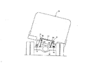
フレーム21に車体13(キャブ)が搭載され、車体13およびフレーム21が車軸15に対して左右へ傾くと、フレーム21の左右において、車軸15との距離が変化する(図3、参照)。縦リンク27の往復運動が横リンク29の回転運動に変換され、車高センサ31の回転軸33へ入力され、車高センサ31の出力(フレーム21と車軸15との距離に相当する電気信号)がコントロールユニット50に入力される。
When the vehicle body 13 (cab) is mounted on the
コントロールユニット50は、入力ポートおよび出力ポートと、ROMおよびRAMと、CPUとからなるマイクロコンピュータにより構成される。入力ポートに車高センサ31のほか、後述の解除スイッチ70が接続される。出力ポートに制御対象となる各種の乗員保護手段が接続される。
The
各種の乗員保護手段については、運転席のシートベルトのプリテンショナ60および助手席のシートベルトのプリテンショナ61、運転席の右側に装備されるエアバック62aおよび助手席の右側に装備されるエアバック63a、運転席の左側に装備されるエアバック62bおよび助手席の左側に装備されるエアバック63b、運転席側のドアに装備されるパワーウインド64の閉側操作手段および助手席側のドアに装備されるパワーウインド65の閉側操作手段、ハンドルの中央部および助手席前方のインストルメントパネルに装備されるエアバック66,67、が設定される。
As for various occupant protection means, the driver
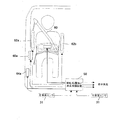
68は車両の横転に係る注意喚起情報の発生手段である。エアバック62a,62b、63a,63bについては、既存のエアバックと異なり、ガス抜き孔を塞ぐ栓と、解除スイッチ70のONにより栓を開封する手段と、が備えられる。図5は、運転席回りの各保護手段の配置(レイアウト)を説明するものであり、60がシートベルトであり、プリテンショナ60aを備える。62a,62bが座席の左右に装備されるエアバック、66がハンドルの中央部に装備されるエアバック、64aがパワーウインドの閉側操作手段、を表示する。図示しないが、助手席側についても、各保護手段が同様に配置される。
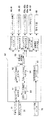
図2は、コントロールユニット50の機能的なブロック構成を表すものであり、ロール角θをを求めるロール角演算手段51、ロール角θの絶対値の単位時間あたりの変化θ’(微分値)を求めるロール角速度演算手段53、ロール角θに基づいて車両が横転へ至る危険度を判定する手段52、ロール角速度θ’に基づいて車両が横転不可避かどうかを判定する手段54、これらの判定に基づいて各出力手段56〜60を制御する手段55、乗員保護解除判定手段61、が備えられる。
FIG. 2 shows a functional block configuration of the
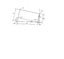
ロール角θは、θ=tan-1(HR−HL)/B、により求められる。図4において、HRが右側の車高センサ31の出力であり、HLが左側の車高センサ31の出力であり、Hは(HR−HL)を表示する。PRは右側の縦リンク27の他端(車軸15に取り付けられる下端)位置であり、PLは左側の縦リンク27の他端(車軸15に取り付けられる下端)位置であり、BがPR位置とPL位置との距離(間隔)を表示する。ロール角演算手段51においては、(HR−HL)に係る正負の符号を付けてロール角θの演算値が出力される。(HR−HL)が正のときは、左方向へのロール、(HR−HL)が負のときは、右方向へのロール、と判定されるのである。
The roll angle θ is obtained by θ = tan −1 (HR−HL) / B. In FIG. 4, HR is the output of the right
ロール角θに基づく判定手段52においては、ロール角θの程度を判定するための基準値(注意喚起レベルθ0、横転危険警報1レベルθ1,横転危険警報2レベルθ2、横転不可避1レベルθ3,横転不可避2レベルθ4)を格納する手段、ロール角θが基準値以上かどうかを判定する手段、ロール角θが特定レベル以上の継続時間Tを判定するための基準値(設定時間T1〜設定時間T4)を格納する手段、継続時間Tが基準値以上かどうかを判定する手段、これらの判定信号(車両が横転へ至る危険度を判定する信号)を出力する手段、を備える。ロール角θの程度を判定するための基準値については、注意喚起レベルθ0<横転危険警報1レベルθ1<横転危険警報2レベルθ2<横転不可避1レベルθ3<横転不可避2レベルθ4、の関係に設定される。
In the determining means 52 based on the roll angle θ, reference values for determining the degree of the roll angle θ (attention level θ 0 ,
ロール角速度θ’に基づく判定手段54においては、ロール角速度θ’の程度を判定する基準値(横転不可避レベルθa’〜横転不可避レベルθd’)を格納する手段、ロール角速度θ’が基準値以上かどうかを判定する手段、その判定信号(車両が横転不可避かどうかの判定信号)を出力する手段、を備える。ロール角速度θ’の程度を判定する基準値については、横転不可避レベルθa’>横転不可避レベルθb’>横転不可避レベルθc’<横転不可避レベルθd’、の関係に設定される。 In the determination means 54 based on the roll angular velocity θ ′, a means for storing a reference value (a roll inevitable level θ a ′ to a roll inevitable level θ d ′) for determining the degree of the roll angular velocity θ ′, and the roll angular velocity θ ′ is a reference value. Means for determining whether or not the above is satisfied, and means for outputting a determination signal (determination signal as to whether the vehicle is inevitable to roll over). 'The reference value determining the degree of rollover unavoidable level theta a' roll velocity theta> rollover unavoidable level theta b '> rollover unavoidable level theta c' <rollover unavoidable level theta d ', is set to the relationship.
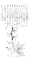
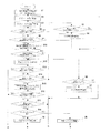
図6および図7は、コントロールユニットの制御内容を説明するフローチャートであり、所定の制御周期毎に実行される。A〜Dは、図6のフローチャートと図7のフローチャートとの接続関係を表示するための符号である。S1においては、車高センサ31の出力(HR,HL)を読み込む。S2においては、ロール角θ=tan-1(HR−HL)/Bを演算する。S3においては、ロール角速度θ’(ロール角|θ|の単位時間あたりの変化)を演算する。S4においては、ロール角速度θ’≧横転不可避レベルθa’かどうかを判定する。S4の判定がyesのときは、S5へ進む一方、S4の判定がnoのときは、S9へ進む。
6 and 7 are flowcharts for explaining the control contents of the control unit, which are executed every predetermined control cycle. A to D are symbols for displaying the connection relationship between the flowchart of FIG. 6 and the flowchart of FIG. In S1, the output (HR, HL) of the
S5においては、ロール角|θ|≦横転危険警報2レベルθ2かどうかを判定する。S5の判定がyesのときは、S6へ進み、ロール角|θ|≧注意喚起レベルθ0かどうかを判定する。S6の判定がyesのときは、S7へ進み、注意喚起情報を発生する一方、S6の判定がnoのときは、リターンへ至る。S5の判定がnoのときは、S6およびS10へ進み、注意喚起情報の発生と共にシートベルト60,61のプリテンショナを作動させる。
In S5, the roll angle | determines whether ≦ rollover danger warning 2 levels theta 2 | theta. If the determination in S5 is yes, the process proceeds to S6, and it is determined whether or not the roll angle | θ | ≧ attention level θ 0 . When the determination of S6 is yes, the process proceeds to S7 and generates alert information, whereas when the determination of S6 is no, the process returns. When the determination of S5 is no, the process proceeds to S6 and S10, and the pretensioner of the
S9においては、ロール角|θ|≧横転危険1レベルθ1かどうかを判定する。S9の判定がyesのときは、S10において、ロール角|θ|≧横転危険1レベルθ1の継続時間Tを計測する。S11においては、継続時間T≧設定時間T2(ロール角|θ|≧横転危険1レベルθ1の継続時間Tが設定時間T2に及ぶ)かどうかを判定する。S11の判定がyesのときは、S12において、シートベルト60,61のプリテンショナを作動させる。S11の判定がnoのときは、リターンへ至るのである。
In S9, it is determined whether or not the roll angle | θ | ≧ 1 rollover risk level 1 θ 1 . If the determination in S9 is yes, in S10, the duration T of the roll angle | θ | ≧ rolling
S4〜S12において、ロール角|θ|≧注意喚起レベルθ0(図9、参照)または注意喚起レベルθ0<ロール角|θ|≦横転危険警報2レベルθ2(図10、参照)のときは、注意喚起情報が発生する。ロール角速度θ’<横転不可避レベルθa’のときは、ロール角|θ|>横転危険警報2レベルθ2になると、シートベルト60,61のプリテンショナが即座に作動する一方、ロール角速度θ’≧横転不可避レベルθa’のときは、ロール角|θ|≧横転危険警報レベルθ1の継続時間Tが設定時間T1に及ぶと、シートベルト60,61のプリテンショナが作動するのである。
In S4 to S12, when the roll angle | θ | ≧ the alert level θ 0 (see FIG. 9) or the alert level θ 0 <the roll angle | θ | ≦ the rollover danger alarm 2 level θ 2 (see FIG. 10) Will generate alert information. When the roll angular velocity θ ′ <the inevitable rollover level θ a ′, the roll angle | θ |> the rollover danger alarm 2 level θ 2 , the pretensioner of the
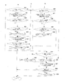
S13においては、ロール角速度θ’≧横転不可避レベルθbかどうかを判定する。S13の判定がyesのときは、S34へ進む一方、S13の判定がnoのときは、S14へ進む。S14においては、ロール角|θ|≧横転不可避1レベルθ3かどうかを判定する。S14の判定がyesのときは、S15において、ロール角|θ|≧横転不可避1レベルθ3の継続時間Tを計測する。S16においては、ロール角速度θ’≧横転不可避レベルθcかどうかを判定する。S16の判定がyesのときは、S34へ進む一方、S16の判定がnoのときは、S17へ進む。S17においては、ロール角|θ|≧横転不可避1レベルθ3の継続時間Tが設定時間T2に及ぶかどうかを判定する。S17の判定がyesのときは、S18において、ロール角θの符号が正(横転方向の前側が左)かどうかを判定する。S18の判定がyesのときは、S19へ進む一方、S18の判定がnoのときは、S25へ進む。 In S13, determines whether the roll angular velocity theta '≧ rollover unavoidable level theta b. When the determination of S13 is yes, the process proceeds to S34, and when the determination of S13 is no, the process proceeds to S14. In S14, it is determined whether or not the roll angle | θ | ≧ rolling inevitable 1 level θ 3 . When the determination in S14 is yes, in S15, the duration T of the roll angle | θ | ≧ rolling inevitable 1 level θ 3 is measured. In S16, it is determined whether or not roll angular velocity θ ′ ≧ rolling inevitable level θ c . When the determination of S16 is yes, the process proceeds to S34, and when the determination of S16 is no, the process proceeds to S17. In S17, the roll angle | determines whether the duration T of ≧ rollover unavoidable 1 Level theta 3 spans set time T 2 | theta. If the determination in S17 is yes, it is determined in S18 whether the sign of the roll angle θ is positive (the front side in the rollover direction is left). When the determination of S18 is yes, the process proceeds to S19, while when the determination of S18 is no, the process proceeds to S25.
S19においては、左側のパワーウインド65の閉側操作手段を作動させる。S20においては、ロール角|θ|≧横転不可避2レベルθ4かどうかを判定する。S20の判定がyesのときは、S34へ進む一方、S20の判定がnoのときは、リターンに至る。S21においては、ロール角|θ|≧横転不可避2レベルθ4の継続時間Tを計測する。S22においては、ロール角速度θ’≧横転不可避レベルθdかどうかを判定する。S22の判定がyesのときは、S34へ進む一方、S22の判定がnoのときは、S23へ進む。S23においては、ロール角|θ|≧横転不可避2レベルθ4の継続時間Tが設定時間T3に及ぶかどうかを判定する。S23の判定がyesのときは、S24において、運転席の左側のエアバック62bおよび助手席の左側のエアバック63bを作動させる一方、S23の判定がnoのときは、リターンに至るのである。
In S19, the closing side operation means of the
S25〜S30においては、右側のパワーウインド64の閉側操作手段,運転席の右側のエアバック62a,助手席の右側のエアバック63aに対してS19〜S23と同一の処理が行われる。S31においては、これらエアバック62b,62bまたはエアバック62a,63aの作動開始からの経過時間Tを計測する。S32においては、これらの作動開始からの経過時間Tが設定時間T4に達するかどうかを判定する。S32の判定がyesのときは、運転席の前方に装備されるエアバック66および助手席の前方に装備されるエアバック67を作動させる。
In S25 to S30, the same processing as S19 to S23 is performed on the closing operation means of the
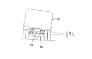
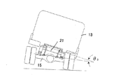
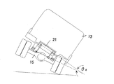
S13〜S33において、ロール角速度θ’が横転不可避レベルθb未満かつ横転不可避レベルθc未満のときは、ロール角|θ|が横転不可避1レベルθ3(図11、参照)以上の継続時間Tが設定値T2に及ぶと、横転方向の前側に装備されるパワーウインド65または64の閉側操作手段が作動する。ロール角速度θ’が横転不可避レベルθb未満かつ横転不可避レベルθc未満かつ横転不可避レベルθd未満のときは、ロール角θが横転不可避2レベルθ4(図12、参照)以上の継続時間Tが設定値T3に及ぶと、座席の両側に装備されるエアバック62a,62b、63a,63bのうち横転方向の前側のエアバック62b,63bまたは62a,63aが作動する。その後、これらの作動開始から計測される時間が設定時間T4に達すると、座席の前方に装備されるエアバック66,67が作動するのである。
In S13~S33, when the roll angular velocity theta 'is less than the rollover unavoidable level theta b below and rollover unavoidable level theta c, roll angle | theta | overturned unavoidable 1 Level theta 3 (FIG. 11, reference) or duration T Reaches the set value T 2 , the closing side operation means of the
S13の判定がnoまたはS16の判定がnoまたはS22の判定がyesのときは、S34へ進み、ロール角θの符号が正(横転方向の前側が左)かどうかを判定する。S34の判定に応じてS35またはS39において、運転席の両側に装備されるエアバック62a,62bのうち横転方向の前側のエアバック62aまたは62b,助手席の両側に装備されるエアバック63a,63bのうち横転方向の前側のエアバック63aまたは63bを作動させる。その後、これらの作動開始から計測される時間が設定時間T4に達すると、座席の前方に装備されるエアバック66、67を作動させる。S13の判定がnoまたはS16の判定がyesのときは、パワーウインド64,65の閉側操作手段は作動しないことになるが、S35およびS39において、必要があれば、パワーウインド64,65の閉側操作手段を作動させるようにしても良い。
If the determination in S13 is no or the determination in S16 is no or the determination in S22 is yes, the process proceeds to S34, and it is determined whether the sign of the roll angle θ is positive (the front side in the rollover direction is left). Depending on the determination of S34, in S35 or S39, among the
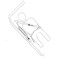
このような構成により、車両の旋回時などにおいて、注意喚起レベルθ0≦ロール角|θ|≦横転危険警報2レベルθ2のときは、注意喚起情報が発生するので、運転者は横転を回避するべく何らかの対処(ブレーキ操作やアクセル操作やハンドル操作)を講じることが可能となる。ロール角|θ|≧横転危険警報2レベルθ2のときは、ロール角速度θ’≧横転不可避レベルθaになると、注意喚起情報の発生と共にシートベルト60,61のプリテンショナが作動する(図15および図16、参照)。プリテンショナの作動により、シートベルト60,61の弛み分が瞬時に巻き取られ、乗員は座席に強く束縛される。つまり、側方への乗員の移動量も最小限に抑えられるのである。
With this configuration, when the vehicle is turning, when the alert level θ 0 ≦ roll angle | θ | ≦ the rollover warning 2 level θ 2 , the alert information is generated, so the driver avoids rollover. It is possible to take some measures (brake operation, accelerator operation, steering wheel operation) as much as possible. Roll angle | theta | when the ≧ rollover danger warning 2 levels theta 2, becomes the roll velocity theta '≧ rollover unavoidable level .theta.a, pretensioner of the
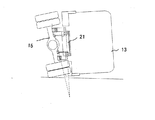
プリテンショナの作動後においても、ロール角速度θ’≧横転不可避レベルθb’,ロール角速度θ’≧横転不可避レベルθc’,ロール角速度θ’≧横転不可避レベルθd’、が順次に判定され、ロール角速度θ’が過大となり、横転不可避が予測されると、エアバック62aまたは62b、63aまたは63bが即座に膨らみ、続いてエアバック66、67も膨らむため、横転時(図13、参照)の衝撃から乗員を保護するクッション機能を遅滞なく適確に確保することができる。
Even after the pretensioner is activated, roll angular velocity θ ′ ≧ rolling inevitable level θ b ′, roll angular velocity θ ′ ≧ rolling inevitable level θ c ′, roll angular velocity θ ′ ≧ rolling inevitable level θ d ′ are sequentially determined, If the roll angular velocity θ ′ becomes excessive and rollover inevitable is predicted, the
ロール角速度θ’<横転不可避レベルθa’またはロール角速度θ’<横転不可避レベルθb’またはロール角速度θ’≧横転不可避レベルθc’または,ロール角速度θ’≧横転不可避レベルθd’のときは、ロール角|θ|の程度およびその特定レベルを越える継続時間Tに基づいて、シートベルト60,61のプリテンショナ,パワーウインド64,65の閉側操作手段,エアバック62aまたは62b、63aまたは63bのガス発生装置,エアバック66,67のガス発生装置、を順次に作動させるので、これらエアバックが必要なく作動する可能性も小さく抑えられるのである。ロール角|θ|が徐々に大きくなるロール状態においては、運転者の対処により、ロール角|θ|が小さく戻されるような場合も考えられるからである。
When roll angular velocity θ '<roll unavoidable level θ a ' or roll angular velocity θ '<roll unavoidable level θ b ' or roll angular velocity θ '≥ roll unavoidable level θ c ' or roll angular velocity θ '≥ roll unavoidable level θ d ' Is based on the degree of the roll angle | θ | and the duration T exceeding the specific level, the pretensioner of the
ロール角速度θ’の程度を判定する基準値については、横転不可避レベルθa’>横転不可避レベルθb’>横転不可避レベルθc’<横転不可避レベルθd’、の関係でなく、横転不可避レベルθa’=横転不可避レベルθb’=横転不可避レベルθc’=横転不可避レベルθd’、の関係に設定することも考えられる。 The reference value for determining the degree of the roll angular velocity θ ′ is the roll inevitable level θ a '> the roll inevitable level θ b '> the roll inevitable level θ c '<the roll inevitable level θ d '. It is also conceivable to set the relationship θ a '= rolling inevitable level θ b ' = rolling inevitable level θ c '= rolling inevitable level θ d '.
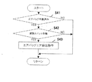
エアバック62a,62b、63a,63b、66,67は、既存のもの異なり、ガス抜き孔を塞ぐ栓を備えるので、横転後においても、ガスが抜けて直ぐに萎むことがなく、乗員を保護するクッション機能を長く維持しえることになる。図8は、乗員保護解除判定手段61の制御内容を説明するフローチャートであり、S41においては、エアバック62aまたは62b、63aまたは63b、66,67が作動済みかどうかを判定する。S42においては、解除スイッチ70がONかどうかを判定する。S41の判定がyesかつS42の判定がyesのときは、S43へ進み、エアバック62aまたは62b、63aまたは63b、66,67のガス抜き孔の栓を開ける処理を行うのである。
Unlike the existing
これにより、横転後において、膨らむエアバック62aまたは62b、63aまたは63b、66,67で乗員が身動き取れない状態が解消され、運転室から随意な脱出が容易に行えるのである。乗員保護解除判定手段61の制御対象は、座席の前方に装備されるエアバック66,67のみでも良く、解除スイッチ70については、シートベルト60,61のロック解除操作に連動させると、シートベルト60,61のロック解除操作のみにより、乗員保護の解除操作が簡単かつ容易に行えるようになる。
Thus, after the rollover, the
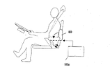
図16は、エアバック62a,62b、63a,63bの代わりに座席のサイドアームレスト80を応用する実施形態を説明するものであり、サイドアームレスト80はスイッチ操作に応じて使用状態から格納状態またはその逆に変位させる駆動機構が備えられる。駆動機構は、コントロールユニット50aにより、エアバック62a,62b、63a,63bと同様に制御され、横転の際にサイドアームレスト80を使用状態に保持するように設定される。もちろん、サイドアームレスト80は、エアバック62a,62b、63a,63bと併用することも可能である。
FIG. 16 illustrates an embodiment in which a
31 車高センサ
50,50a コントロールユニット
51 ロール角演算手段
52 ロール角に基づく横転判定手段
53 ロール角速度演算手段
54 ロール角速度に基づく横転判定手段
55 保護手段の制御手段
61 乗員保護解除判定手段
60,61 プリテンショナ式シートベルト
62a,62b 、63a,63b 座席両側のエアバック
66,67 座席前方のエアバック
64,65 パワーウインド
68 注意喚起情報発生手段
70 解除スイッチ
31
Claims (5)
Priority Applications (1)
| Application Number | Priority Date | Filing Date | Title |
|---|---|---|---|
| JP2004118990A JP4634734B2 (en) | 2004-04-14 | 2004-04-14 | Vehicle occupant protection device |
Applications Claiming Priority (1)
| Application Number | Priority Date | Filing Date | Title |
|---|---|---|---|
| JP2004118990A JP4634734B2 (en) | 2004-04-14 | 2004-04-14 | Vehicle occupant protection device |
Publications (2)
| Publication Number | Publication Date |
|---|---|
| JP2005297846A true JP2005297846A (en) | 2005-10-27 |
| JP4634734B2 JP4634734B2 (en) | 2011-02-16 |
Family
ID=35329906
Family Applications (1)
| Application Number | Title | Priority Date | Filing Date |
|---|---|---|---|
| JP2004118990A Expired - Fee Related JP4634734B2 (en) | 2004-04-14 | 2004-04-14 | Vehicle occupant protection device |
Country Status (1)
| Country | Link |
|---|---|
| JP (1) | JP4634734B2 (en) |
Cited By (3)
| Publication number | Priority date | Publication date | Assignee | Title |
|---|---|---|---|---|
| JP2007314015A (en) * | 2006-05-25 | 2007-12-06 | Mazda Motor Corp | Vehicle occupant protection device |
| JP2016060464A (en) * | 2014-09-22 | 2016-04-25 | 富士重工業株式会社 | Crew protection device |
| WO2018235700A1 (en) * | 2017-06-20 | 2018-12-27 | テイ・エス テック株式会社 | Vehicle seat |
Citations (6)
| Publication number | Priority date | Publication date | Assignee | Title |
|---|---|---|---|---|
| JPH10297423A (en) * | 1997-04-24 | 1998-11-10 | Toyota Motor Corp | Control system for occupant head protection device |
| JP2000127891A (en) * | 1998-10-23 | 2000-05-09 | Toyota Motor Corp | Ignition control method for vehicle occupant protection device |
| JP2001260806A (en) * | 2000-03-22 | 2001-09-26 | Honda Motor Co Ltd | Vehicle occupant protection system |
| JP2003112598A (en) * | 2001-06-28 | 2003-04-15 | Robert Bosch Corp | Vehicle rollover detection system and method of operating the same |
| JP2004029008A (en) * | 2002-05-13 | 2004-01-29 | Indiana Mills & Manufacturing Inc | Roll sensor system for vehicles |
| JP2004026072A (en) * | 2002-06-27 | 2004-01-29 | Denso Corp | Starter for occupant protection device |
-
2004
- 2004-04-14 JP JP2004118990A patent/JP4634734B2/en not_active Expired - Fee Related
Patent Citations (6)
| Publication number | Priority date | Publication date | Assignee | Title |
|---|---|---|---|---|
| JPH10297423A (en) * | 1997-04-24 | 1998-11-10 | Toyota Motor Corp | Control system for occupant head protection device |
| JP2000127891A (en) * | 1998-10-23 | 2000-05-09 | Toyota Motor Corp | Ignition control method for vehicle occupant protection device |
| JP2001260806A (en) * | 2000-03-22 | 2001-09-26 | Honda Motor Co Ltd | Vehicle occupant protection system |
| JP2003112598A (en) * | 2001-06-28 | 2003-04-15 | Robert Bosch Corp | Vehicle rollover detection system and method of operating the same |
| JP2004029008A (en) * | 2002-05-13 | 2004-01-29 | Indiana Mills & Manufacturing Inc | Roll sensor system for vehicles |
| JP2004026072A (en) * | 2002-06-27 | 2004-01-29 | Denso Corp | Starter for occupant protection device |
Cited By (4)
| Publication number | Priority date | Publication date | Assignee | Title |
|---|---|---|---|---|
| JP2007314015A (en) * | 2006-05-25 | 2007-12-06 | Mazda Motor Corp | Vehicle occupant protection device |
| JP2016060464A (en) * | 2014-09-22 | 2016-04-25 | 富士重工業株式会社 | Crew protection device |
| WO2018235700A1 (en) * | 2017-06-20 | 2018-12-27 | テイ・エス テック株式会社 | Vehicle seat |
| US11407335B2 (en) | 2017-06-20 | 2022-08-09 | Ts Tech Co., Ltd. | Vehicle seat |
Also Published As
| Publication number | Publication date |
|---|---|
| JP4634734B2 (en) | 2011-02-16 |
Similar Documents
| Publication | Publication Date | Title |
|---|---|---|
| US9994181B1 (en) | Vehicle seat including airbag | |
| JP3220118B2 (en) | System for protecting vehicle occupants during a vehicle capsize | |
| JPH08239007A (en) | Tire air-pressure sensing type air bag for car | |
| JPH05213144A (en) | Protector for vehicle occupant | |
| JP2992961B2 (en) | Automotive airbag equipment | |
| JP4923731B2 (en) | Vehicle occupant protection device | |
| KR20090007103A (en) | Car Roof Air Bag | |
| JP5087081B2 (en) | Side impact airbag control device | |
| JP4634734B2 (en) | Vehicle occupant protection device | |
| JP6673170B2 (en) | Occupant protection device | |
| JP4232039B2 (en) | Crew restraint system | |
| JP2004276790A (en) | Air bag and air bag apparatus | |
| JP2008519720A (en) | Car with occupant restraint system | |
| JP2009073207A (en) | Airbag control device and occupant crash protection system | |
| JPH0986338A (en) | Airbag device | |
| JP3951426B2 (en) | Vehicle occupant protection device | |
| JP3558703B2 (en) | Occupant protection device | |
| JP4343733B2 (en) | Curtain airbag device for vehicle | |
| CN110027497B (en) | Motor vehicles with fabric doors | |
| KR100224235B1 (en) | Car interior pressure reduction device in case of air bag explosion | |
| JP4487665B2 (en) | Vehicle seat belt device | |
| KR19980083798A (en) | Car seat control device | |
| JPH09132111A (en) | Vehicle occupant protection system | |
| KR100189439B1 (en) | How to set the car airbag system and airbag-passenger seating position | |
| JPH0858509A (en) | Air bag device for vehicle |
Legal Events
| Date | Code | Title | Description |
|---|---|---|---|
| A621 | Written request for application examination |
Free format text: JAPANESE INTERMEDIATE CODE: A621 Effective date: 20070322 |
|
| A131 | Notification of reasons for refusal |
Free format text: JAPANESE INTERMEDIATE CODE: A131 Effective date: 20090519 |
|
| A521 | Request for written amendment filed |
Free format text: JAPANESE INTERMEDIATE CODE: A523 Effective date: 20090716 |
|
| A131 | Notification of reasons for refusal |
Free format text: JAPANESE INTERMEDIATE CODE: A131 Effective date: 20100119 |
|
| A521 | Request for written amendment filed |
Free format text: JAPANESE INTERMEDIATE CODE: A523 Effective date: 20100319 |
|
| A131 | Notification of reasons for refusal |
Free format text: JAPANESE INTERMEDIATE CODE: A131 Effective date: 20100810 |
|
| A521 | Request for written amendment filed |
Free format text: JAPANESE INTERMEDIATE CODE: A523 Effective date: 20100929 |
|
| TRDD | Decision of grant or rejection written | ||
| A01 | Written decision to grant a patent or to grant a registration (utility model) |
Free format text: JAPANESE INTERMEDIATE CODE: A01 Effective date: 20101026 |
|
| A01 | Written decision to grant a patent or to grant a registration (utility model) |
Free format text: JAPANESE INTERMEDIATE CODE: A01 |
|
| A61 | First payment of annual fees (during grant procedure) |
Free format text: JAPANESE INTERMEDIATE CODE: A61 Effective date: 20101119 |
|
| R150 | Certificate of patent or registration of utility model |
Free format text: JAPANESE INTERMEDIATE CODE: R150 |
|
| FPAY | Renewal fee payment (event date is renewal date of database) |
Free format text: PAYMENT UNTIL: 20131126 Year of fee payment: 3 |
|
| R250 | Receipt of annual fees |
Free format text: JAPANESE INTERMEDIATE CODE: R250 |
|
| R250 | Receipt of annual fees |
Free format text: JAPANESE INTERMEDIATE CODE: R250 |
|
| LAPS | Cancellation because of no payment of annual fees |