JP2005297870A - Seat sliding device - Google Patents
Seat sliding device Download PDFInfo
- Publication number
- JP2005297870A JP2005297870A JP2004119543A JP2004119543A JP2005297870A JP 2005297870 A JP2005297870 A JP 2005297870A JP 2004119543 A JP2004119543 A JP 2004119543A JP 2004119543 A JP2004119543 A JP 2004119543A JP 2005297870 A JP2005297870 A JP 2005297870A
- Authority
- JP
- Japan
- Prior art keywords
- anchor plate
- belt anchor
- rail
- upper rail
- reinforcing member
- Prior art date
- Legal status (The legal status is an assumption and is not a legal conclusion. Google has not performed a legal analysis and makes no representation as to the accuracy of the status listed.)
- Pending
Links
- 230000003014 reinforcing effect Effects 0.000 claims description 25
- 238000003466 welding Methods 0.000 claims description 4
- 230000002787 reinforcement Effects 0.000 abstract description 23
- 238000011156 evaluation Methods 0.000 description 4
- 238000000034 method Methods 0.000 description 3
- 238000000926 separation method Methods 0.000 description 3
- 230000002159 abnormal effect Effects 0.000 description 2
- 230000000694 effects Effects 0.000 description 2
- 230000008646 thermal stress Effects 0.000 description 2
Images

Landscapes
- Seats For Vehicles (AREA)
Abstract
Description
本発明は、車両の床面に固定されるロアレール上に、シートを支持するアッパーレールを摺動可能に設けるとともに、該アッパーレールに、シートベルトのベルトアンカープレートを取り付けて成るシートスライド装置に関する。 The present invention relates to a seat slide device in which an upper rail that supports a seat is slidably provided on a lower rail fixed to a floor surface of a vehicle, and a belt anchor plate of a seat belt is attached to the upper rail.
車両の床面に固定されるロアレールと、該ロアレールに摺動可能に係合されてシートを支持するアッパーレールとを有し、該アッパーレールにレール方向に沿ってベルトアンカープレートを取り付けたシートスライド装置が提供されている。 A seat slide having a lower rail fixed to a vehicle floor and an upper rail that is slidably engaged with the lower rail and supports a seat, and a belt anchor plate is attached to the upper rail along the rail direction A device is provided.
ベルトアンカーをアッパーレール側に有し、シートベルトに過大な荷重が加わった時にアッパーレールがロアレールから剥離してしまうことを防止するようにしたシートスライド装置として、下記(1)(2)を挙げることができる。
(1)ロアレールと該ロアレール上を摺動するアッパーレールとにレール方向に沿う係合部を設けるとともに、ベルトアンカーブラケットをアッパーレールに取り付けて成り、ベルトアンカーブラケットに設けたフランジとロアレールの係合部上面との間に微小な隙間を有するようにしたシートスライド装置(特許文献1,参照)。シートベルトに過大な力が加わった時、ベルトアンカーブラケットのフランジでロアレールを押さえて一体化することにより、アッパーレールとロアレールとの剥離を防止している。
(2)前後二つの支持位置で床面上に支持した一対のロアレール上を摺動する一対のアッパーレールによりシートクッションフレームを支持するとともに、該シートクッションフレームの後部にベルトアンカーを固定して成り、シートベルトに過大な力が加わった時のロアレールの最大変形部位が前記二つの支持位置の中間よりも前側となるように、アッパーレールとの係合部より下方のロアレールの断面形状を段階的に変化させたシートスライド装置(特許文献2,参照)。
The following (1) and (2) are listed as seat slide devices having a belt anchor on the upper rail side and preventing the upper rail from peeling off from the lower rail when an excessive load is applied to the seat belt. be able to.
(1) The lower rail and the upper rail sliding on the lower rail are provided with an engaging portion along the rail direction, and the belt anchor bracket is attached to the upper rail, and the engagement between the flange provided on the belt anchor bracket and the lower rail A seat slide device having a minute gap between the upper surface and the upper surface (see Patent Document 1). When an excessive force is applied to the seat belt, the lower rail is pressed and integrated with the flange of the belt anchor bracket to prevent separation between the upper rail and the lower rail.
(2) The seat cushion frame is supported by a pair of upper rails that slide on a pair of lower rails supported on the floor surface at two front and rear support positions, and a belt anchor is fixed to the rear portion of the seat cushion frame. The cross-sectional shape of the lower rail below the engaging portion with the upper rail is stepped so that the maximum deformation portion of the lower rail when an excessive force is applied to the seat belt is on the front side of the middle of the two support positions. The seat slide device changed to (see Patent Document 2).
ベルトアンカーをアッパーレール側に取り付けたシートスライド装置では、過大な所定の荷重をシートベルトに加える評価試験に於いて、アッパーレールがロアレールから剥離しないことが要求される。
ベルトアンカーをアッパーレール側に取り付けたシートスライド装置の一例として、アッパーレールにレール方向に沿って延びるベルトアンカープレートを取り付けたシートスライド装置がある。このシートスライド装置では、評価試験に応じて決まる所定の荷重がシートベルトに加えられた時に、ベルトアンカープレートがレール方向の中央付近で折れ曲がり、これにより、アッパーレールがロアレールから剥離してしまう場合がある。
本発明は、床面上に固定されるロアレールと該ロアレール上を摺動するシート支持用のアッパーレールとを有し、該アッパーレールにレール方向に沿って延びるベルトアンカープレートを取り付けたシートスライド装置に於いて、上記の評価試験でアッパーレールがロアレールから剥離しないようにすることを目的とする。
なお、前記特許文献1は、ベルトアンカーブラケットとそのフランジがアッパーレールの後部に設けられているシートスライド装置に関する剥離防止技術であり、本願の目的とする構成のシートスライド装置に関する技術ではない。
また、前記特許文献2は、断面T字状で該T字の上辺の両側に下垂部を有するロアレールと、該ロアレールの下垂部を外側から包むように係合する係合部を両側に備えたアッパーレールとから成るシートスライド装置に関する剥離防止技術であり、本願の目的とする構成のシートスライド装置に関する技術ではない。
In the seat slide device in which the belt anchor is attached to the upper rail side, it is required that the upper rail does not peel from the lower rail in an evaluation test in which an excessive predetermined load is applied to the seat belt.
As an example of a seat slide device in which a belt anchor is attached to the upper rail side, there is a seat slide device in which a belt anchor plate extending along the rail direction is attached to the upper rail. In this seat slide device, when a predetermined load determined according to the evaluation test is applied to the seat belt, the belt anchor plate bends near the center in the rail direction, which may cause the upper rail to peel off from the lower rail. is there.
The present invention relates to a seat slide device having a lower rail fixed on a floor surface and a seat supporting upper rail sliding on the lower rail, and a belt anchor plate extending along the rail direction being attached to the upper rail. The purpose of the above is to prevent the upper rail from peeling off from the lower rail in the above evaluation test.
Note that Patent Document 1 is a technique for preventing separation related to a seat slide device in which a belt anchor bracket and its flange are provided at the rear portion of the upper rail, and is not a technology related to a seat slide device having a configuration intended by the present application.
Patent Document 2 discloses a lower rail having a T-shaped cross section and having a hanging portion on both sides of the upper side of the T-shape, and an upper provided on both sides with an engaging portion that engages the lower rail so as to wrap the hanging portion from the outside. This is a technique for preventing separation related to a seat slide device including a rail, and is not a technology related to a seat slide device having a configuration intended by the present application.
本発明は、下記[1]〜[3]のように構成される。なお、下記[1]〜[3]に於いて、符号は本発明の理解を助けるために付したものであり、本発明の範囲を符号の部材での構成に限定する趣旨ではない。
[1]構成1:
床面に固定されるロアレール10と、該ロアレール10に摺動可能に係合されてシートを支持するアッパーレール50とを有し、該アッパーレール50にレール方向に沿ってベルトアンカープレート60を取り付けて成るシートスライド装置であって、
前記ベルトアンカープレート60にレール方向に沿って一体に固定され、該ベルトアンカープレート60とともに箱型断面の筒を構成する補強部材70を有する、
ことを特徴とするシートスライド装置。
The present invention is configured as the following [1] to [3]. In addition, in the following [1] to [3], the reference numerals are given to help the understanding of the present invention, and the scope of the present invention is not intended to be limited to the configuration of the reference numerals.
[1] Configuration 1:
The
The
A seat slide device characterized by that.
[2]構成2:
請求項1に於いて、
前記アッパーレール50は、前記ベルトアンカープレート60の取付範囲に於いて、前記補強部材70が固定される側へ延設された張出部51と、該張出部51の根元近傍の下方位置に設けられた貫通孔52とを有し、
前記ベルトアンカープレート60は、取付状態で前記アッパーレール50の貫通孔52に対応する部位に貫通孔62を有し、
前記補強部材70は、固定状態で前記アッパーレール50の張出部51に下側から係合する係合部71を有するとともに、該係合部の先端に前記アッパーレール50及びベルトアンカープレート60の貫通孔52,62に対応する突出片72を有し、
前記補強部材70の係合部71を前記アッパーレール50の張出部51の下側から係合させるとともに該係合部71の先端の突出片72を前記アッパーレール50更に前記ベルトアンカープレート60の貫通孔52,62に挿通して突出させた後、該先端部72aを前記ベルトアンカープレート60に溶接して成る、
ことを特徴とするシートスライド装置。
[3]構成3:
構成2に於いて、
前記ベルトアンカープレート60は、前記補強部材70が固定される側へ延設された張出部61を有し、
前記補強部材70は、固定状態で前記ベルトアンカープレート60の張出部61に下側から係合する張出部75を有し、
前記補強部材70の張出部75と前記ベルトアンカープレート60の張出部61を溶接して成る、
ことを特徴とするシートスライド装置。
[2] Configuration 2:
In claim 1,
The
The
The reinforcing
The
A seat slide device characterized by that.
[3] Configuration 3:
In configuration 2,
The
The reinforcing
The overhanging
A seat slide device characterized by that.
構成1のシートベルト装置は、床面に固定されるロアレール10と、該ロアレール10に摺動可能に係合されてシートを支持するアッパーレール50とを有し、該アッパーレール50にレール方向に沿ってベルトアンカープレート60を取り付けて成るとともに、該ベルトアンカープレート60にレール方向に沿って一体に固定されて該ベルトアンカープレート60とともに箱型断面の筒を構成する補強部材70を有するため、評価試験に応じて決まる所定の荷重がシートベルトに加えられた時にもベルトアンカープレート60がレール方向の中央付近で折れ曲がることが防止され、アッパーレール50がロアレール10から剥離することも防止される。
The seat belt device according to Configuration 1 includes a
構成2のシートベルト装置は、構成1に於いて、前記アッパーレール50は前記ベルトアンカープレート60の取付範囲に於いて前記補強部材70が固定される側へ張り出す張出部51と該張出部51の根元近傍の下方位置に設けられた貫通孔52とを有し、前記ベルトアンカープレート60は取付状態で前記アッパーレール50の貫通孔52に対応する部位に貫通孔62を有し、前記補強部材70は固定状態で前記アッパーレール50の張出部51に下側から係合する係合部71を有するとともに該係合部の先端に前記アッパーレール50及びベルトアンカープレート60の貫通孔52,62に対応する突出片72を有し、前記補強部材70の係合部71を前記アッパーレール50の張出部51の下側から係合させるとともに該係合部71の先端の突出片72を前記アッパーレール50更に前記ベルトアンカープレート60の貫通孔52,62に挿通して突出させた後、該先端部72aを前記ベルトアンカープレート60に溶接して成るため、補強部材70がベルトアンカープレート60とアッパーレール50に更に強固に一体化され、その結果、構成1が持つ効果が更に良好に発揮される。また、補強部材70をアッパーレール50に溶接する必要が無いため、溶接の熱応力でアッパーレール50のレール方向端部に反りが発生することもなく、したがって、その反りに起因してアッパーレール50とロアレール10とにガタツキや異音が発生するという不具合もない。
構成3のシートベルト装置は、構成2に於いて、前記ベルトアンカープレート60は前記補強部材70が固定される側へ延設された張出部61を有し、前記補強部材70は固定状態で前記ベルトアンカープレート60の張出部61に下側から係合する張出部75を有し、前記補強部材70の張出部75と前記ベルトアンカープレート60の張出部61を溶接して成るため、補強部材70がベルトアンカープレート60とアッパーレール50に更に強固に一体化され、その結果、構成2が持つ効果が更に良好に発揮される。
The seat belt device according to the second aspect is the same as that of the first aspect, wherein the
The seatbelt device according to Configuration 3 is that, in Configuration 2, the
以下、図面を参照して本発明の実施の形態を説明する。
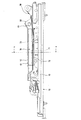
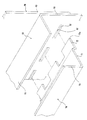
図1は本実施の形態のシートスライド装置をリンフォース(補強部材)70側から見た正面図、図2は図1内a−a線断面図、図3はリンフォース70をアッパーレール50に取り付ける様子を示す斜視図である。
Embodiments of the present invention will be described below with reference to the drawings.
1 is a front view of the seat slide device according to the present embodiment as viewed from the reinforcement (reinforcing member) 70 side, FIG. 2 is a cross-sectional view taken along the line aa in FIG. 1, and FIG. It is a perspective view which shows a mode that it attaches.
ロアレール10は、車両の床面上に固定される。
ロアレール10は、底部14と、底部14の両側(図2での両側)からそれぞれ上方へ立設された壁部13,13と、両壁部13,13からそれぞれ内側へ延設された天板部12,12と、両天板部12,12からそれぞれ下方へ下垂された下垂部11,11とを有する。なお、図2に於いて左側の下垂部11は、アッパーレール50により回動可能に支持されているロックプレート80の下張出部に所定間隔で設けられているロック孔82に侵入してアッパーレール50をロアレール10に対してロックするためのロック歯として形成されている。ロックプレート80によりアッパーレール50をロアレール10に対してロックする機構は周知であり、本発明の要旨にも関連しないため、本明細書でのこれ以上の説明は省略する。
The
The
ロアレール10の底部14上には、複数のコロ(不図示)を下端側に保持するアッパーレール50が、前後方向(図1で左右方向)へ摺動可能に係合されている。
アッパーレール50は、鉛直方向に設けられる壁部53と、壁部53の上縁部分からリンフォース70側(図2で左方)へ張り出すように直角に折り曲げて延設された張出部51と、壁部53の下部から張出部51と反対方向へ直角に折り曲げて延設された底部56と、底部56の先端縁から上方へ折り曲げて延設された上立部57とを有する。また、アッパーレール50には、リンフォース70の複数の突出片72,72,,,が挿通される複数の貫通孔52,52,,,が、前記張出部51の根元近傍の下方位置に、レール方向に沿って間欠的に設けられている。また、アッパーレール50の壁部53には、前記ロックプレート80の上張出部81が通過される貫通孔55が設けられている。
On the bottom 14 of the
The
アッパーレール50の壁部53の上縁部付近には、ベルトアンカープレート60の壁部63の下縁部付近が、不図示のリベットで固定されている。なお、リベットは、レール方向(前後方向;図1で左右方向)の4箇所(不図示)に用いられている。
ベルトアンカープレート60は、上記の如く、ベルトアンカープレート60の壁部63がアッパーレール50の壁部53にリベットで固定されているため、ベルトアンカープレート60の壁部63もまた、鉛直方向に設けられることとなる。この壁部63の上縁部分から、リンフォース70側(図2で左方)へ張り出すようにして、張出部61が直角に折り曲げて延設されている。また、ベルトアンカープレート60には、リンフォース70の複数の突出片72,72,,,が挿通される複数の貫通孔62,62,,,が、アッパープレートの複数の貫通孔52,52,,,と同一部位に設けられている。なお、図1内に示す65は、ベルトアンカー位置である。
Near the upper edge of the
As described above, since the
リンフォース70は、ベルトアンカープレート60及びアッパーレール50に一体に固定されることにより鉛直方向に設けられる壁部73と、壁部73の上縁部分からベルトアンカープレート60側(図2で右方)へ張り出すように直角に折り曲げて延設された張出部75と、壁部73の下縁部分からベルトアンカープレート60側へ張り出すように直角に折り曲げて延設された係合部71と、係合部71の先端の段部71aからベルトアンカープレート60側へ突出された複数の突出片72,72,,,とを有する。リンフォース70のレール方向の長さは、ベルトアンカープレート60のレール方向の直線部(断面形状が変化しない範囲)と略同等であり、該直線部より若干短い。
The
リンフォース70をベルトアンカープレート60及びアッパーレール50に溶接等で一体に固定する手順を説明する。
リンフォース70の張出部75の上面をベルトアンカープレート60の張出部61の下面に押し当てるとともに、リンフォース70の係合部71の上面をアッパーレール50の張出部51の下面に押し当てる。この時、レール方向(前後方向;図1で左右方向)でのリンフォース70とベルトアンカープレート60(及びアッパーレール50)との相対位置は、リンフォース70の係合部71の先端から延設された複数の突出片72,72,,,を、それぞれ、アッパーレール50の対応する複数の貫通孔52,52,,,に挿通することができ、さらに、ベルトアンカープレート60の対応する複数の貫通孔62,62,,に挿通することができる位置である。
A procedure for integrally fixing the
The upper surface of the protruding
上記のように押し当てた後、リンフォース70の張出部75の上面の露出部分と、ベルトアンカープレート60の張出部61の先端とを溶接する。この溶接部分を、図2にY2として示す。また、リンフォース70の係合部71の先端から延設された複数の突出片72,72,,が、ベルトアンカープレート60の複数の貫通孔62,62,,から突出している部分72a,72a,,,の上面を、それぞれベルトアンカープレート60に溶接する。この溶接部分を、図2にY1として示す。
After pressing as described above, the exposed portion of the upper surface of the
このようにして、リンフォース70が、ベルトアンカープレート60及びアッパーレール50に一体に固定されて、図2に示すように、リンフォース70とベルトアンカープレート60とにより箱型断面の筒が構成される。このため、評価試験に応じて決まる所定の荷重がシートベルト(不図示)に加えられた時にもベルトアンカープレート60がレール方向の中央付近で折れ曲がることが防止され、アッパーレール50がロアレール10から剥離することも防止される。
また、上記の固定に際しては、リンフォース70とベルトアンカープレート60のみを溶接しているため、アッパーレール50のレール方向の端部に溶接の熱応力に起因する反りが発生せず、したがって、反りに起因するガタツキや異音も生じない。
In this way, the
Further, at the time of fixing, since only the
10 ロアレール
11 ロアレール下垂部
12 ロアレール天板部
13 ロアレール壁部
14 ロアレール底部
50 アッパーレール
51 アッパーレールの張出部
52,52,,, アッパーレールの貫通孔
53 アッパーレールの壁部
55 アッパーレルのロックプレート通過孔
56 アッパーレール底部
57 アッパーレール上立部
60 ベルトアンカープレート
61 ベルトアンカープレートの張出部
62,62,,, ベルトアンカープレートの貫通孔
63 ベルトアンカープレートの壁部
65 シートベルトのベルトアンカー位置
70 リンフォース(補強部材)
71 リンフォースの係合部
71a リンフォースの係合部の段部
72,72,,, リンフォースの突出片
72a,72a,,, リンフォースの突出片先端部
73 リンフォースの壁部
75 リンフォースの張出部
80 ロックプレート
82 ロック孔
Y1 溶接部分
Y2 溶接部分
DESCRIPTION OF
71
Claims (3)
前記ベルトアンカープレートにレール方向に沿って一体に固定され、該ベルトアンカープレートとともに箱型断面の筒を構成する補強部材を有する、
ことを特徴とするシートスライド装置。 A seat slide device comprising: a lower rail fixed to a floor surface; an upper rail that is slidably engaged with the lower rail and supports a seat; and a belt anchor plate is attached to the upper rail along the rail direction. Because
The belt anchor plate is integrally fixed along the rail direction, and has a reinforcing member that forms a box-shaped cross-section cylinder together with the belt anchor plate.
A seat slide device characterized by that.
前記アッパーレールは、前記ベルトアンカープレートの取付範囲に於いて、前記補強部材が固定される側へ延設された張出部と、該張出部の根元近傍の下方位置に設けられた貫通孔とを有し、
前記ベルトアンカープレートは、取付状態で前記アッパーレールの貫通孔に対応する部位に貫通孔を有し、
前記補強部材は、固定状態で前記アッパーレールの張出部に下側から係合する係合部を有するとともに、該係合部の先端に前記アッパーレール及びベルトアンカープレートの貫通孔に対応する突出片を有し、
前記補強部材の係合部を前記アッパーレールの張出部の下側から係合させるとともに該係合部の先端の突出片を前記アッパーレール更に前記ベルトアンカープレートの貫通孔に挿通して突出させた後、該先端部を前記ベルトアンカープレートに溶接して成る、
ことを特徴とするシートスライド装置。 In claim 1,
The upper rail includes a projecting portion extending to a side to which the reinforcing member is fixed and a through hole provided at a lower position near the base of the projecting portion in the belt anchor plate mounting range. And
The belt anchor plate has a through hole in a portion corresponding to the through hole of the upper rail in the attached state,
The reinforcing member has an engaging portion that engages with the protruding portion of the upper rail from below in a fixed state, and a protrusion corresponding to the through hole of the upper rail and the belt anchor plate at the tip of the engaging portion. Have a piece,
The engaging portion of the reinforcing member is engaged from the lower side of the protruding portion of the upper rail, and the protruding piece at the tip of the engaging portion is inserted through the through hole of the upper rail and the belt anchor plate to protrude. And then welding the tip to the belt anchor plate.
A seat slide device characterized by that.
前記ベルトアンカープレートは、前記補強部材が固定される側へ延設された張出部を有し、
前記補強部材は、固定状態で前記ベルトアンカープレートの張出部に下側から係合する張出部を有し、
前記補強部材の張出部と前記ベルトアンカープレートの張出部を溶接して成る、
ことを特徴とするシートスライド装置。 In claim 2,
The belt anchor plate has an overhang extending to the side on which the reinforcing member is fixed,
The reinforcing member has an overhanging portion that engages with the overhanging portion of the belt anchor plate from below in a fixed state.
The overhanging portion of the reinforcing member and the overhanging portion of the belt anchor plate are welded.
A seat slide device characterized by that.
Priority Applications (1)
| Application Number | Priority Date | Filing Date | Title |
|---|---|---|---|
| JP2004119543A JP2005297870A (en) | 2004-04-14 | 2004-04-14 | Seat sliding device |
Applications Claiming Priority (1)
| Application Number | Priority Date | Filing Date | Title |
|---|---|---|---|
| JP2004119543A JP2005297870A (en) | 2004-04-14 | 2004-04-14 | Seat sliding device |
Publications (1)
| Publication Number | Publication Date |
|---|---|
| JP2005297870A true JP2005297870A (en) | 2005-10-27 |
Family
ID=35329927
Family Applications (1)
| Application Number | Title | Priority Date | Filing Date |
|---|---|---|---|
| JP2004119543A Pending JP2005297870A (en) | 2004-04-14 | 2004-04-14 | Seat sliding device |
Country Status (1)
| Country | Link |
|---|---|
| JP (1) | JP2005297870A (en) |
Cited By (4)
| Publication number | Priority date | Publication date | Assignee | Title |
|---|---|---|---|---|
| CN107161042A (en) * | 2017-06-29 | 2017-09-15 | 长春富维安道拓汽车饰件系统有限公司 | Detachable automotive seat |
| JP2021181282A (en) * | 2020-05-20 | 2021-11-25 | トヨタ紡織株式会社 | Seat frame |
| JP2023141104A (en) * | 2022-03-23 | 2023-10-05 | 日本発條株式会社 | Vehicle seat frames and vehicle seats |
| JP2024036595A (en) * | 2020-03-20 | 2024-03-15 | テイ・エス テック株式会社 | vehicle seat |
-
2004
- 2004-04-14 JP JP2004119543A patent/JP2005297870A/en active Pending
Cited By (8)
| Publication number | Priority date | Publication date | Assignee | Title |
|---|---|---|---|---|
| CN107161042A (en) * | 2017-06-29 | 2017-09-15 | 长春富维安道拓汽车饰件系统有限公司 | Detachable automotive seat |
| CN107161042B (en) * | 2017-06-29 | 2023-06-30 | 长春富维安道拓汽车饰件系统有限公司 | Detachable automobile seat |
| JP2024036595A (en) * | 2020-03-20 | 2024-03-15 | テイ・エス テック株式会社 | vehicle seat |
| JP7684613B2 (en) | 2020-03-20 | 2025-05-28 | テイ・エス テック株式会社 | Vehicle seats |
| JP2021181282A (en) * | 2020-05-20 | 2021-11-25 | トヨタ紡織株式会社 | Seat frame |
| JP7352836B2 (en) | 2020-05-20 | 2023-09-29 | トヨタ紡織株式会社 | seat frame |
| JP2023141104A (en) * | 2022-03-23 | 2023-10-05 | 日本発條株式会社 | Vehicle seat frames and vehicle seats |
| JP7713901B2 (en) | 2022-03-23 | 2025-07-28 | 日本発條株式会社 | Vehicle seat frame and vehicle seat |
Similar Documents
| Publication | Publication Date | Title |
|---|---|---|
| JP4090820B2 (en) | Child seat mounting structure | |
| US7322648B2 (en) | Child seat | |
| JP2009154752A (en) | Vehicle seat slide device | |
| JP5466969B2 (en) | Steering column device | |
| JPH1148896A (en) | Air bag device for vehicle | |
| JP2005297870A (en) | Seat sliding device | |
| KR20140059113A (en) | Drive of a seat adjusting device for motor vehicles | |
| JPH11334428A (en) | Slide lower rail cover mounting structure | |
| JP2002154354A (en) | Vehicle seat slide device | |
| JP2019085030A (en) | Side airbag device | |
| JP4991491B2 (en) | Counter mounting structure | |
| JP6963170B2 (en) | Vehicle seat | |
| CN111483357A (en) | Sliding device | |
| JP6950441B2 (en) | Vehicle seat | |
| JP2001225681A (en) | Rear floor structure of car body | |
| JP7312381B2 (en) | Mounting structure of mounting member | |
| JP5892775B2 (en) | Child seat anchor device | |
| JP3757493B2 (en) | Airbag device mounting structure | |
| JP2019031156A (en) | Vehicle seat | |
| JP4809274B2 (en) | Instrument panel mounting structure | |
| JP5515086B2 (en) | Retainer fixing structure for seat belt anchor | |
| JP4808008B2 (en) | Vehicle engine mounting structure | |
| JP2009255871A (en) | Meter mounting structure | |
| JP4973134B2 (en) | Vehicle slide seat structure | |
| JP6497905B2 (en) | Vehicle seat positioning structure |
Legal Events
| Date | Code | Title | Description |
|---|---|---|---|
| A621 | Written request for application examination |
Effective date: 20070323 Free format text: JAPANESE INTERMEDIATE CODE: A621 |
|
| A977 | Report on retrieval |
Effective date: 20090525 Free format text: JAPANESE INTERMEDIATE CODE: A971007 |
|
| A131 | Notification of reasons for refusal |
Free format text: JAPANESE INTERMEDIATE CODE: A131 Effective date: 20090609 |
|
| A02 | Decision of refusal |
Free format text: JAPANESE INTERMEDIATE CODE: A02 Effective date: 20091110 |