JP2005298008A - Outlet member and liquid storage bag - Google Patents
Outlet member and liquid storage bag Download PDFInfo
- Publication number
- JP2005298008A JP2005298008A JP2004116747A JP2004116747A JP2005298008A JP 2005298008 A JP2005298008 A JP 2005298008A JP 2004116747 A JP2004116747 A JP 2004116747A JP 2004116747 A JP2004116747 A JP 2004116747A JP 2005298008 A JP2005298008 A JP 2005298008A
- Authority
- JP
- Japan
- Prior art keywords
- liquid
- valve body
- valve seat
- spout member
- bag
- Prior art date
- Legal status (The legal status is an assumption and is not a legal conclusion. Google has not performed a legal analysis and makes no representation as to the accuracy of the status listed.)
- Withdrawn
Links
Images
Landscapes
- Bag Frames (AREA)
- Closures For Containers (AREA)
Abstract
【課題】 液体収容袋に収容された液体を注出口部材により注出させるものにおいて、収容袋の取り扱いを容易にする。
【解決手段】 フィルム状部材からなる側壁5及び底壁6を組み合わせて袋本体3を構成する。袋本体3の側壁5に注出口部材4を熱溶着する。注出口部材4の筒状体7を上流側部材と下流側部材とに分割する。上流側部材の端壁部に円形の孔部を形成して弁座を構成する。下流側部材の内面に帯状の支持部を介して弁体を一体成形する。上流側部材に下流側部材を組み付けた状態で、弁体が弁座に圧接するように支持部により弁体に対し付勢力を作用させる。袋本体3の側壁5を手で持った際に、弁体が受ける液体による力に抗するように支持部の付勢力を設定する。
【選択図】 図2
PROBLEM TO BE SOLVED: To facilitate handling of a storage bag, in which liquid stored in a liquid storage bag is poured out by a spout member.
A bag body 3 is formed by combining a side wall 5 and a bottom wall 6 made of a film-like member. The spout member 4 is thermally welded to the side wall 5 of the bag body 3. The tubular body 7 of the spout member 4 is divided into an upstream member and a downstream member. A valve seat is formed by forming a circular hole in the end wall of the upstream member. A valve body is integrally formed on the inner surface of the downstream member via a belt-like support portion. In a state where the downstream member is assembled to the upstream member, a biasing force is applied to the valve body by the support portion so that the valve body is pressed against the valve seat. When the side wall 5 of the bag body 3 is held by hand, the urging force of the support portion is set so as to resist the force caused by the liquid received by the valve body.
[Selection] Figure 2
Description
本発明は、液体収容袋に収容された液体を注出するための注出口部材及び該注出口部材を備えた液体収容袋に関する。 The present invention relates to a spout member for pouring out a liquid stored in a liquid storage bag and a liquid storage bag including the spout member.
一般に、例えば硬質樹脂製の容器に収容された液状洗剤を使い切った後に、詰替用の液体収容袋に収容された液状洗剤を上記硬質容器に詰め替えることが行われている。このようにすることで、硬質容器を再利用でき、また、液体収容袋を小さく折り畳んでから廃棄することができて、ゴミの減量化を図ることができる。 In general, for example, after the liquid detergent contained in a container made of hard resin is used up, the liquid detergent contained in the liquid container for refilling is refilled into the hard container. By doing so, the hard container can be reused, and the liquid storage bag can be discarded after being folded small, thereby reducing the amount of dust.
この種の液体収容袋として、複数枚の樹脂製フィルム状部材を重ね、これらフィルム状部材の対応する周縁同士を熱溶着することで収容袋本体を構成し、この収容袋本体に収容された液体を注出する注出口部材を設けたものがある(例えば、特許文献1、2参照)。これらのものでは、注出口部材が収容袋本体の上部に配置され、この注出口部材を容器に差し込むことで詰め替え作業を容易に行うことができる。
ところが、上記特許文献1、2の液体収容袋は、収容袋本体がフィルム状部材で構成されているため、手で持った際や傾けた際に収容袋本体が変形して内部の液体が注出口部材を介して漏れる。このため、液体収容袋を持つ位置や持ち方に気を使わなければならず、取り扱いが煩わしくなってしまう。
However, in the liquid storage bags of
本発明は斯かる点に鑑みてなされたものであり、その目的とするところは、液体収容袋の液体が注出口部材を介して漏れないようにして、液体収容袋の取り扱いを容易にすることにある。 The present invention has been made in view of such points, and an object of the present invention is to facilitate the handling of the liquid storage bag by preventing the liquid in the liquid storage bag from leaking through the spout member. It is in.
上記目的を達成するために、本発明では、注出口部材に弁座と、該弁座に着座する弁体とを設け、該弁体を所定の付勢力で弁座に着座させるようにした。 In order to achieve the above object, in the present invention, the spout member is provided with a valve seat and a valve body seated on the valve seat, and the valve body is seated on the valve seat with a predetermined urging force.
具体的には、請求項1の発明は注出口部材の発明であり、液体を収容する液体収容袋に熱溶着して設けられる注出口部材であって、液体が流通する流通路を有する筒状体を備え、上記筒状体が上記収容袋と熱溶着可能に構成されると共に、上記筒状体には、弁座と、該弁座に着座する方向に付勢されて上記流通路を閉じる弁体とが設けられ、上記弁体の付勢力は、液体を注出する際に上記弁体が上記弁座から離れるように設定されている構成とする。
Specifically, the invention of
この構成によれば、筒状体が収容袋に熱溶着され、筒状体と収容袋との間から内部の液体が漏れるのを防止することが可能となる。また、注出口部材を設けた収容袋を取り扱う場合に、例えば収容袋の側壁を持った際には、該収容袋の液体が流通路を通って外部へ流れようとし、この液体の圧力により弁体が弁座から離れる向きの力を受ける。このとき、弁体が着座方向に付勢されているので、弁体が弁座から離れる方向に変位せず、流通路が閉じられた状態で保持され、その結果、収容袋の液体が注出口部材を介して漏れることはない。 According to this configuration, the cylindrical body is thermally welded to the storage bag, and it is possible to prevent the liquid inside from leaking between the cylindrical body and the storage bag. Further, when handling the storage bag provided with the spout member, for example, when holding the side wall of the storage bag, the liquid in the storage bag tends to flow to the outside through the flow path, and the pressure of the liquid causes a valve. The body is subjected to force away from the valve seat. At this time, since the valve body is biased in the seating direction, the valve body is not displaced in the direction away from the valve seat, and the flow path is held in a closed state. There is no leakage through the member.
一方、液体を注出する場合に収容袋の側壁を比較的強く押さえると、弁体が液体から受ける力が、弁体の着座方向への付勢力よりも大きくなる。このことで、弁体が弁座から離れる方向に変位して流通路が開いた状態となり、収容袋の液体が注出される。 On the other hand, if the side wall of the containing bag is pressed relatively strongly when liquid is poured out, the force that the valve body receives from the liquid becomes greater than the urging force in the seating direction of the valve body. As a result, the valve body is displaced in a direction away from the valve seat to open the flow passage, and the liquid in the containing bag is poured out.
請求項2の発明では、液体を収容する液体収容袋に熱溶着して設けられる注出口部材であって、液体が流通する流通路を有する筒状体を備え、上記筒状体には、熱溶着基部と、弁座と、該弁座に着座する方向に付勢されて上記流通路を閉じる弁体とが設けられ、上記弁体の付勢力は、液体を注出する際に上記弁体が上記弁座から離れるように設定されている構成とする。 According to a second aspect of the present invention, the spout member is provided by being thermally welded to a liquid storage bag for storing a liquid, and includes a cylindrical body having a flow passage through which the liquid flows. A welding base, a valve seat, and a valve body that is biased in the direction of seating on the valve seat and closes the flow passage are provided, and the biasing force of the valve body is such that when the liquid is poured out, the valve body Is configured to be separated from the valve seat.
この構成によれば、熱溶着基部が収容袋に熱溶着されるので、注出口部材が収容袋にしっかりと取り付けられ、筒状体と収容袋との間から内部の液体が漏れるのを防止することが可能となる。また、請求項1の発明と同様に、注出口部材を設けた収容袋を取り扱う場合に、収容袋の液体が注出口部材を介して漏れるのが防止されるとともに、液体を注出する場合には液体収容袋の液体が筒状体から注出される。 According to this configuration, since the heat welding base is thermally welded to the storage bag, the spout member is firmly attached to the storage bag and prevents the liquid inside from leaking between the cylindrical body and the storage bag. It becomes possible. Similarly to the first aspect of the invention, when handling a storage bag provided with a spout member, the liquid in the storage bag is prevented from leaking through the spout member, and the liquid is discharged. The liquid in the liquid storage bag is poured out from the cylindrical body.
請求項3の発明では、請求項1または2の発明において、上記弁座は上記流通路の液体流れ方向の中途部に設けられる一方、上記弁体は上記弁座よりも液体流れ方向の下流側に設けられ、上記弁体を液体流れ方向の上流側に付勢して上記弁座に着座させる付勢手段が設けられている構成とする。 According to a third aspect of the invention, in the first or second aspect of the invention, the valve seat is provided in a midway portion of the flow passage in the liquid flow direction, while the valve body is downstream of the valve seat in the liquid flow direction. And a biasing means for biasing the valve body upstream in the liquid flow direction and seating on the valve seat.
この構成によれば、弁座及び弁体を筒状体の内部に位置付けておきながら、付勢手段により弁体を弁座に着座させることが可能となる。 According to this configuration, the valve body can be seated on the valve seat by the biasing means while the valve seat and the valve body are positioned inside the cylindrical body.
請求項4の発明では、請求項3の発明において、上記筒状体は樹脂材を成形してなり、上記弁体及び上記付勢手段は上記筒状体に一体成形されている構成とする。 According to a fourth aspect of the present invention, in the third aspect of the present invention, the cylindrical body is formed by molding a resin material, and the valve body and the biasing means are integrally formed with the cylindrical body.
この構成によれば、部品点数が削減されて注出口部材の製造工数を削減することが可能となる。また、付勢手段が樹脂材で構成されているので、樹脂材が有する弾性を利用して弁体を付勢することが可能となる。 According to this configuration, it is possible to reduce the number of parts and reduce the man-hours for manufacturing the spout member. Further, since the urging means is made of a resin material, it is possible to urge the valve body using the elasticity of the resin material.
請求項5の発明では、請求項4の発明において、上記筒状体は液体流れ方向に分割された上流側部材と下流側部材との組み合わせ体であり、上記上流側部材に上記弁座が一体成形され、上記下流側部材に上記弁体及び上記付勢手段が一体成形されている構成とする。
In the invention of
この構成によれば、弁座と、弁体及び付勢手段とを別々に成形することが可能となる。 According to this configuration, the valve seat, the valve body, and the urging means can be formed separately.
請求項6の発明では、請求項4の発明において、上記筒状体の径方向に半割りにされた2つの半体が樹脂材により一体成形されこれら2つの半体の開放側を合わせて上記筒状体が構成され、一方の半体に上記弁体及び上記付勢手段が一体成形されている構成とする。 According to a sixth aspect of the present invention, in the fourth aspect of the present invention, the two halves divided in half in the radial direction of the cylindrical body are integrally formed of a resin material, and the open sides of the two halves are combined to form the above A cylindrical body is configured, and the valve body and the urging means are integrally formed in one half.
この構成によれば、部品点数が削減されて注出口部材の製造工数を削減することが可能となる。 According to this configuration, it is possible to reduce the number of parts and reduce the man-hours for manufacturing the spout member.
請求項7の発明は液体収容袋の発明であり、請求項1ないし6のいずれか1つに記載の注出口部材をフィルム状部材からなる袋本体に熱溶着した構成とする。
The invention of
この構成によれば、請求項1及び2の発明と同様に、収容袋を取り扱う場合には、流通路が閉じられた状態で保持されて収容袋の液体が注出口部材を介して漏れることはなく、また、液体を注出する場合には、流通路が開いた状態となって収容袋の液体が注出される。 According to this configuration, similarly to the first and second aspects of the invention, when the storage bag is handled, the liquid in the storage bag is leaked through the spout member while being held in a state where the flow passage is closed. In addition, when the liquid is poured out, the liquid in the containing bag is poured out with the flow path opened.
請求項8の発明では、請求項7の発明において、上記袋本体には、上記筒状体を密封する覆い部が設けられている構成とする。 According to an eighth aspect of the present invention, in the seventh aspect of the present invention, the bag body is provided with a cover portion for sealing the cylindrical body.
この構成によれば、液体を注出するまでの間、筒状体が覆い部により密封されて外部の空気等に触れるのが回避される。 According to this configuration, until the liquid is poured out, it is avoided that the cylindrical body is sealed by the cover portion and touches external air or the like.
請求項9の発明では、請求項8の発明において、上記覆い部に脆弱部が設けられている構成とする。 According to the ninth aspect of the present invention, in the eighth aspect of the present invention, the cover portion is provided with a fragile portion.
この構成によれば、脆弱部を起点としてフィルム状部材を破断させることで覆い部を切り取ることが可能となる。 According to this configuration, the cover portion can be cut off by breaking the film-like member starting from the fragile portion.
請求項1の発明によれば、注出口部材の筒状体を収容袋と熱溶着可能に構成したので、筒状体と収容袋との間から内部の液体が漏れるのを防止することができる。そして、この筒状体に、弁座と、該弁座に着座する方向に付勢された弁体とを設け、液体を注出する際に弁体が弁座から離れるように付勢力を設定したので、この注出口部材を設けた収容袋を取り扱う場合に注出口部材を介して液体が漏れるのも防止することができて、収容袋を持つ位置や持ち方の自由度が向上し、収容袋を容易に取り扱うことができる。 According to the first aspect of the present invention, since the cylindrical body of the spout member is configured to be heat weldable to the storage bag, it is possible to prevent the liquid inside from leaking between the cylindrical body and the storage bag. . The tubular body is provided with a valve seat and a valve body biased in the direction of seating on the valve seat, and a biasing force is set so that the valve body is separated from the valve seat when liquid is poured out. Therefore, when handling a storage bag provided with this spout member, it is possible to prevent liquid from leaking through the spout member, and the position of holding the storage bag and the degree of freedom of holding are improved. The bag can be handled easily.
請求項2の発明によれば、請求項1の発明と同様に、筒状体と収容袋との間から内部の液体が漏れるのを防止することができるとともに、収容袋を取り扱う場合に注出口部材を介して液体が漏れるのも防止することができて、収容袋を容易に取り扱うことができる。
According to the invention of claim 2, as in the invention of
請求項3の発明によれば、弁座を流通路の液体流れ方向の中途部に設け、弁体を弁座よりも液体流れ下流側に設け、この弁体を付勢手段により付勢したので、弁座及び弁体を筒状体の内部に収容して注出口部材をコンパクトに構成しながら、流通路を確実に閉じることができる。
According to the invention of
請求項4の発明によれば、弁体及び付勢手段を樹脂製の筒状体に一体成形したので、製造工数を削減できるとともに、別途部材を設けずに弁体へ付勢力を作用させることができ、これらのことにより、注出口部材のコストを低減することができる。
According to invention of
請求項5の発明によれば、筒状体を上流側部材と下流側部材とに分割し、上流側部材に弁座を一体成形し、下流側部材に弁体及び付勢手段を一体成形したので、弁座と、弁体及び付勢手段とを別々の成形面により成形することが可能となって、各々の形状設定の自由度を高めることができる。
According to the invention of
請求項6の発明によれば、一体成形された2つの半体を合わせて筒状体を構成し、一方の半体に弁体及び付勢手段を一体成形したので、部品点数を削減することができて、注出口部材のコストを低減することができる。 According to the sixth aspect of the present invention, the two integrally formed halves are combined to form a cylindrical body, and the valve body and the biasing means are integrally formed in one half, so that the number of parts can be reduced. And the cost of the spout member can be reduced.
請求項7の発明によれば、請求項1の発明と同様に、収容袋を取り扱う場合に注出口部材から液体が漏れるのを防止することができるので、収容袋を容易に取り扱うことができる。 According to the seventh aspect of the invention, similarly to the first aspect of the invention, it is possible to prevent liquid from leaking from the spout member when handling the storage bag, so that the storage bag can be handled easily.
請求項8の発明によれば、筒状体を覆い部により密封したので、例えば、収容袋を薬液の収容袋として筒状体を滅菌処理した際、薬液を注出するまでの間、筒状体の滅菌状態を保持することができる。
According to the invention of
請求項9の発明では、覆い部に脆弱部を設けたので、覆い部を容易に切り取ることができる。 In the invention of claim 9, since the fragile portion is provided in the cover portion, the cover portion can be easily cut off.
以下、本発明の実施形態を図面に基づいて詳細に説明する。 Hereinafter, embodiments of the present invention will be described in detail with reference to the drawings.
《発明の実施形態1》
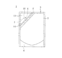
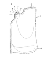
図2は、本発明に係る液体収容袋1を示し、この液体収容袋1は、液体として例えば液体洗剤、調味料、飲料水や薬液等を収容することができるものである。
FIG. 2 shows a
上記収容袋1は、側面視で矩形状をなし底壁部が略だ円形に形成された自立性の袋本体3と、該袋本体3の上側の角部近傍に配設された本発明に係る注出口部材4とを備えている。袋本体3は、フィルム状部材からなる2枚の側壁5と、同様なフィルム状部材からなる底壁6とで構成されている。上記側壁5及び底壁6を構成するフィルム状部材としては少なくとも最内層が熱溶着性を有するフィルムが用いられる。具体的には、ポリエチレンやポリプロピレンなどの熱溶着性を有するシーラント層と、二軸延伸ナイロンフィルムや二軸延伸ポリエチレンテレフタレートフィルムなどの延伸フィルムからなる外層とを積層させてなる2層構造のものや、それらの間に金属箔、紙、無機質蒸着層、エチレン−ビニルアルコール共重合体層などを挟んだ3層以上のものを用いることが可能である。これらの層は複数用いられてもよい。これらの積層にはドライラミネートや押し出しラミネートなどの積層方法が好適に用いられる。
The
上記両側壁5は重ね合わされて対応する縁部同士がそれぞれ互いに熱溶着されており、また、底壁6の周縁は上記両側壁5の下縁に熱溶着されている。この収容袋1に液体を収容すると底壁6が略水平に広がって袋本体3は下側へ行くほど広がり、立った姿勢を維持できるような形状となる。つまり、この収容袋1はいわゆるスタンディングパウチ(自立性包装袋)である。
The
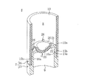
上記注出口部材4は、図1に示すように、例えばポリエチレンやポリプロピレン等の樹脂材を両端が開口する円筒状に成形してなる筒状体7を備えている。筒状体7を構成する樹脂は袋本体3と熱溶着が可能である必要があり、少なくとも一部が袋本体3のシーラント層と共通の樹脂であることが好ましい。つまり、袋本体3のシーラント層がポリエチレンである場合には筒状体7の少なくとも一部がポリエチレンであることが好ましく、袋本体3のシーラント層がポリプロピレンである場合には筒状体7の少なくとも一部がポリプロピレンであることが好ましい。筒状体7の形状や大きさは特に制限はなく目的に応じて設計することができる。通常は、円筒形状が多用され、外径は3〜30mm程度で肉厚は0.3〜5.0mm程度に設定され、上記側壁5よりも変形し難く形成されている。
As shown in FIG. 1, the
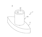
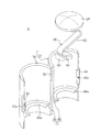
また、図1の注出口部材4では設けていないが、図2〜図4に図示するように、この筒状体7には外周面から径方向に延出する熱溶着基部Fが一体成形されている。該熱溶着基部Fは、径方向の一方向と、この一方向に正反対の方向とに比較的大きく舟形に延出しており、この熱溶着基部Fの側面を上記両側壁5に熱溶着することにより、注出口部材4と両側壁5との間からの液体の漏れを確実に防止することが可能となる。熱溶着基部Fの側面には、熱溶着をより確実にするために溝や凸条を形成しておくことが好ましい。
Although not provided in the
なお、熱溶着基部は側壁5同士に挟持されるのではなく、側壁5に穿孔を設け、袋本体3内側から筒状体7を突出させる場合には円盤状の熱溶着基部を用いることが好ましい。
The heat welding base is not sandwiched between the
図1に示すように、注出口部材4の下端に位置する開口は、袋本体3の内部に連通し液体を注出口部材4の内部の流通路8に導入するための導入口9とされ、一方、注出口部材4の上端に位置する開口は、流通路8に導入された液体を外部に注出するための注出口10とされている。
As shown in FIG. 1, the opening located at the lower end of the
また、上記両側壁5の注出口部材4よりも上側は、図2および図11に示すように、注出口部材4の注出口10を覆うように形成されてそれらの周縁部同士が互いに熱溶着され、この部分により覆い部13が構成され筒状体7が密封されている。この覆い部13には、少なくともシーラント層の一部を残して形成されたミシン目やレーザー光線によるハーフカットなどの薄肉部からなる脆弱部14が形成されており、この脆弱部14に沿って両側壁5を破断させることで覆い部13を切り取ることが可能となっている。
Further, the upper side of the
このように注出口部材4の筒状体7が覆われていることによって、食品や薬品等を収容する場合、内溶液の殺菌と共に注出口部材7も殺菌することができ、開封するまで注出口10の衛生性を確保することができる。
Thus, when food, a medicine, etc. are accommodated by covering
図1に示すように、上記筒状体7は、その中心線方向である液体の流れ方向に分割された上流側部材15と下流側部材16との組み合わせ体である。上流側部材15の中心線方向の長さは、下流側部材16の中心線方向の長さよりも短く設定されている。上流側部材15の導入口9側の外径は、上記下流側部材16の外径と略同じに設定される一方、上流側部材15の注出口10側は、外径が上記下流側部材16の内径と略同じに設定された小径部15aとされ、この小径部15aに上記下流側部材16が外嵌されるようになっている。また、上流側部材15の小径部15aの外周面には、周方向に連続または断続した複数の突起15bが形成され、一方、下流側部材16の内周面には、上記小径部15aの突起15bに対応して凹部16aが形成されており、これら突起15b及び凹部16aが係合するようになっている。
As shown in FIG. 1, the
上記上流側部材15には弁座21が設けられており、この弁座21は、上流側部材15の注出口10側端部に一体成形された平坦な端壁部22の略中央部に円形の孔部23を形成してなるものである。端壁部22は、注出口部材4の中心線に略直交して延びており、また、孔部23の内周面は、端壁部22の注出口10側へ行くほど拡径するテーパ面に形成されている。さらに、端壁部22の外周縁22aには面取りが施されており、下流側部材16を小径部15aに容易に外嵌させることが可能となっている。
The
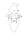
上記下流側部材16の内部には上記弁座21に着座する弁体25が設けられている。該弁体25は、球体の下半部に近似した形状を有し、上面の略中央部に窪みが形成されている。この弁体25は、図3にも示すように、下流側部材16の周方向に略等間隔に設けられた3つの支持部26を介して上記下流側部材16の内面に支持されており、この支持部26は、本発明の付勢手段である。各支持部26は、弁体25の上端部から上方へ湾曲して下流側部材16の内面へ向けて延びる細長い帯状に形成されており、その両端部は弁体25及び下流側部材16の内面にそれぞれ一体成形されている。そして、上記上流側部材15に下流側部材16を外嵌させることにより、上流側部材15の突起15bが上流側部材16の凹部16aに係合して両部材15、16が一体化するとともに、弁体25が弁座21に接する。
A
上記支持部26は、弁体25に対し弁座21側へ付勢力を作用させるように形成されていて、通常時には、弁体25が弁座21に圧接して流通路8が閉じられている。この支持部26による弁体25への付勢力は、収容袋1を取り扱う場合に注出口部材4から袋本体3の液体が漏れないように、かつ液体を注出する場合には注出口部材4から液体がスムーズに注出されるように設定されている。
The
すなわち、収容袋1を取り扱う場合には、側壁5を手で持ったり、収容袋1を傾けたりすることがあり、このときには、収容袋1に収容されている液体が注出口部材4の流通路8を通って注出口10へ向かって流れようとする。この液体の圧力により、図1に矢印イで示すように、弁体25が液体流れ方向の下流側向きである弁座21から離れる向きの力を受ける。この場合に弁体25が弁座21から離れないように支持部26による付勢力を設定することで、流通路8の閉状態が保持されて注出口部材4からの液体の漏れが防止される。尚、この付勢力は、収容袋1が倒れた場合に、液体から受ける力によっても弁体25が弁座21から離れないように設定されている。
That is, when the
一方、液体の注出を行う場合には、注出を行う者が収容袋1の側壁5を比較的強く押さえることで、注出口10へ向かって流れようとする液体の圧力が、上記した取り扱いの場合の圧力よりも大きくなって弁体25が比較的大きな力を受ける。この場合に弁体25が弁座21から離れるように支持部26による付勢力を設定することで、注出の場合にのみ弁体25及び弁座21間に隙間が生じて液体の注出が可能となる。尚、この付勢力の設定は、支持部26の肉厚や形状、数等により任意に行うことが可能である。
On the other hand, when the liquid is poured out, the pressure of the liquid that tends to flow toward the
したがって、この実施形態によれば、収容袋1の側壁5を持って移動させたり、また収容袋1を傾けたりした際には、弁体25が上記の如き付勢力で弁座21に圧接されているので、流通路8が閉状態で保持され、注出口部材4から液体が漏れるのを防止することができる。これにより、収容袋1を持つ位置や持ち方の自由度が向上するとともに、収容袋1を移動させるときの姿勢の自由度も向上し、収容袋1の取り扱いを容易にすることができる。さらに、収容袋1が倒れた場合にも、注出口部材4からの液体の漏れを防止することができる。
Therefore, according to this embodiment, the
そして、例えば液体を別の容器に詰め替える場合には、注出口部材4の注出口10側を容器の開口に差し込んだ後、収容袋1の側壁5を比較的強く押さえることで、流通路8が開状態となって注出口部材4から液体が注出されて詰め替えを行うことができる。また、この詰め替えの際には、注出口部材4が側壁部5よりも変形し難く構成されているので、液体の流通路8が狭まるように変形するのが防止されて、液体をスムーズに詰め替えることができる。また、収容袋1の容量等によって取り扱いの場合に弁体25が液体から受ける力が異なるが、この弁体25が受ける力に応じた付勢力が得られるように支持部26を形成することができる。
For example, when refilling the liquid into another container, after inserting the
また、弁体25及び支持部26を注出口部材4の内面に一体成形したので、部品点数が削減されて注出口部材4の製造工数を削減できる。さらに、支持部26が樹脂材で成形されているので、別途部材を設けずに、樹脂材が有する弾性を利用して弁体25を付勢することができる。これらのことにより、注出口部材4および収容袋1のコストを低減することができる。
Further, since the
また、上流側部材15に弁座21を一体成形し、下流側部材16に弁体25及び支持部26を一体成形したので、弁座21と、弁体25及び支持部26とを別々の成形面で成形することが可能となり、各々の形状設定の自由度を高めることができる。
Further, since the
《発明の実施形態2》
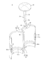
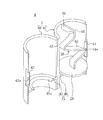
図5及び図6は、本発明の実施形態2に係る注出口部材4を示し、図示しないが、この実施形態2の袋本体3は上記実施形態1のものと同じであるので、以下、袋本体3の説明を省略し、注出口部材4の構造についてのみ説明する。
<< Embodiment 2 of the Invention >>
FIGS. 5 and 6 show the
上記注出口部材4の筒状体7は、径方向に半割りにされた第1半体40及び第2半体41を薄肉ヒンジ42を介した状態で樹脂材により一体成形して、これら第1半体40及び第2半体41を薄肉ヒンジ42周りに回動させて両半体40、41の開放側を合わせて構成されるようになっている。第1半体40の薄肉ヒンジ42と反対側の縁部における中央部には、略平坦な片状部43が形成されており、この片状部43の外面の略中心部には円形の突起43aが形成されている。また、第2半体41の薄肉ヒンジ42と反対側の縁部には、両半体40、41を合わせた状態で上記片状部43の外面側に位置するように平坦部44が形成され、この平坦部44の上記突起43aに対応する部位には、該突起43aが係合する係合孔44aが形成されている。第1半体40及び第2半体41を合わせた状態で突起43aを係合孔44aに係合させることにより、両半体40、41が離れずに保持され、図示しないが、実施形態1と同様な導入口及び注出口が形成される。
The
上記第1半体40及び第2半体41の内面の導入口側(図5及び図6の下側)には、両半体40、41を合わせた状態で弁座21を構成する円弧状部45、46がそれぞれ一体成形されている。両円弧状部45、46は同様に形成されていて、第1半体40側のものについてのみ説明すると、円弧状部45は、第1半体40の内面から該第1半体40の内側へ向けて延び、その先端面は円弧面45aとされ、第1半体40及び第2半体41を合わせると、両円弧面45a、46aにより円形の孔部が形成されるようになっている。また、各円弧状部45、46の円弧面45a、46aは、その注出口側(図5及び図6の上側)へ行くほど半体40、41の内面に近づく傾斜面に形成されている。
On the inlet side (lower side of FIGS. 5 and 6) of the inner surfaces of the
上記第2半体41の注出口側の縁部には導入口側へ向かう切欠部48が形成され、この切欠部48の底縁部には、上記弁座21に当接する弁体25が、付勢手段としての支持部26を介して設けられている。該支持部26は、一端部が切欠部48の底縁部に薄肉ヒンジ50を介して連結された第1棒状部51と、該第1棒状部51の他端部に薄肉ヒンジ52を介して連結された第2棒状部53とを備えており、上記両薄肉ヒンジ50、52も支持部26の構成要素である。
A
上記弁体25は、図6に示すように、注出口部材4の径方向に延びる円盤状に形成され、この弁体25の第2棒状部53との連結側の面は略平坦に形成される一方、反対側の面は、図5に示すように、弁体25の中心部が周縁部よりも厚肉となるように形成された凸面をなし、この凸面が弁座21に接する。
As shown in FIG. 6, the
上記支持部26の薄肉ヒンジ50、52の形状は、弁体25に弁座21側への付勢力が作用するように設定されていて、実施形態1と同様に弁体25が弁座21に圧接して流通路8が閉じられている。上記支持部26による弁体25への付勢力は、実施形態1の支持部26による付勢力と同様に設定されており、この付勢力の設定は、薄肉ヒンジ50、52の形状や肉厚等により任意に行うことが可能である。
The shape of the thin hinges 50 and 52 of the
次に、この注出口部材4の製造要領について説明すると、まず、図5に示すように、第1半体40及び第2半体41が展開した状態で、かつ第1棒状部51及び第2棒状部53が注出口部材4の中心線方向外側へ延びた状態で各部を成形する。成形後、図6に示すように、第1棒状部51を薄肉ヒンジ50周りに第2半体41の内側へ折り曲げ、さらに第2棒状部53を薄肉ヒンジ52周りに折り曲げて弁体25を第1半体40の円弧面45aに圧接させる。しかる後、図示しないが、第1半体40及び第2半体41を薄肉ヒンジ42周りに回動させて両半体40、41の開放側を合わせて突起43aを係合孔44aに係合させることで、弁体25が弁座21に圧接した状態となって注出口部材4が得られる。
Next, the manufacturing procedure of the
したがって、この実施形態によれば、上記実施形態1と同様に、収容袋1を取り扱う場合に、注出口部材4から液体が漏れるのを防止することができて、収容袋1の取り扱いを容易にすることができる。
Therefore, according to this embodiment, when handling the
また、第1半体40及び第2半体41を一体成形し、これら半体40、41に弁体25、弁座21及び支持部26を一体成形したので、部品点数が削減されて注出口部材4の製造工数が削減される。これにより、注出口部材4および収容袋1のコストを低減することができる。
Further, since the
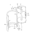
尚、上記実施形態2では、支持部26の第1棒状部51が注出口部材4の中心線方向外側に延びた状態で支持部26を成形するようにしているが、これに限らず、図7及び図8に示す変形例1のように、第1棒状部51が第2半体41の内側に折れ曲がった状態でかつ第2棒状部53が注出口部材4の中心線方向外側に延びた状態で成形してもよい。このように成形することで、成形後に第1棒状部51を成形したままの状態として、第2棒状部53のみを薄肉ヒンジ52周りに約180度回動させるだけで弁体25を円弧面46aに圧接させることができて、製造工程の簡素化を図ることができる。
In the second embodiment, the
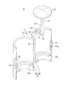
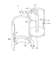
また、図9及び図10に示す変形例2のように、注出口部材4の支持部26に屈曲部62を形成するようにしてもよい。すなわち、支持部26は第2半体41の注出口側の内面から径方向内側へ突出する突出部60と、該突出部60の先端部に薄肉ヒンジ61を介して連結された屈曲部62とから構成されている。この屈曲部62の薄肉ヒンジ61と反対側の端部に弁体25が一体成形されている。上記屈曲部62は、図10に示すように、薄肉ヒンジ61に連結された部分から弁体25側へ向かって、第1半体40及び第2半体41間の薄肉ヒンジ42に近接するように屈曲した後、この屈曲部分と反対側へ屈曲して延びており、この屈曲部62の形状により弁体25に弁座21側への付勢力が作用するようになっている。この屈曲部62による付勢力は、実施形態1の付勢力と同様に設定されており、屈曲部62の肉厚等により任意に設定可能である。
Moreover, you may make it form the bending
次に、この注出口部材4の製造要領について説明すると、まず、図9に示すように、第1半体40及び第2半体41を展開した状態で、かつ屈曲部62が注出口部材4の中心線方向外側へ延びた状態で各部を成形する。その後、図10に示すように、屈曲部62を薄肉ヒンジ61周りに折り曲げて弁体25を円弧面46aに圧接させ、しかる後、第1半体40及び第2半体41の開放側を合わせて突起43aを係合孔44aに係合させることで、弁体25が弁座21に圧接した状態となって注出口部材4が得られる。
Next, the manufacturing procedure of the
尚、上記実施形態1、2では、覆い部13により筒状体7の注出口10を覆うようにしたので、例えば収容袋1を薬液の収容袋とし筒状体7を滅菌処理した際、輸送時等に筒状体7の注出口10が外部の空気等に触れるのを回避することができ、筒状体7の滅菌状態を保持することができる。
In the first and second embodiments, since the
また、覆い部13に脆弱部14を形成したので、覆い部13を引っ張ることで脆弱部14に沿って側壁5を破断して、覆い部14を容易に切り取ることができる。
Moreover, since the
さらに、上記各実施形態では、注出口部材4に弁体25、支持部26及び弁座21を一体成形するようにしているが、これらは注出口部材4と別体に成形してから該注出口部材4に組み付けるようにしてもよい。
Further, in each of the above embodiments, the
そして、袋本体3の形状としては、図11に示す変形例のように、注出口部材4が溶着される部位周辺を該注出口部材4の中心線方向に延びるように形成してもよい。この場合、舟形形状の熱溶着基部Fが設けられているとより確実な熱溶着を行うことができ好ましい。そして、舟形形状の熱溶着基部Fは注出口部材4の両側部のほぼ全長に亘って設けられていても良い。また、熱溶着基部Fを設けても設けなくても、筒状体7の周方向に複数の溝または凸条を設けておくことができる。
And as a shape of the bag
さらに、注出口部材4の配設位置も制限されることなく、例えば、袋本体3の側壁5に設定してもよい。この場合は筒状体7に円盤状の熱溶着基部を設けるとともに、側壁5に開口を形成し、この開口に筒状体7を内側から貫通させ、開口の周縁内面と円盤状の熱溶着基部とを熱溶着すればよい。
Furthermore, the arrangement position of the
以上説明したように、本発明に係る注出口部材及び液体収容袋は、例えばフィルム状部材からなる収容袋本体を備えたものに用いることができる。 As described above, the spout member and the liquid storage bag according to the present invention can be used for a storage bag body including a film-like member, for example.
1 収容袋
3 袋本体
4 注出口部材
5 側壁(フィルム状部材)
7 筒状体
10 注出口
13 覆い部
14 脆弱部
15 上流側部材
16 下流側部材
21 弁座
25 弁体
26 支持部(付勢手段)
40 第1半体
41 第2半体
F 熱溶着基部
1
7
40
Claims (9)
液体が流通する流通路を有する筒状体を備え、
上記筒状体が上記収容袋と熱溶着可能に構成されると共に、
上記筒状体には、弁座と、該弁座に着座する方向に付勢されて上記流通路を閉じる弁体とが設けられ、
上記弁体の付勢力は、液体を注出する際に上記弁体が上記弁座から離れるように設定されていることを特徴とする注出口部材。 A spout member provided by heat welding to a liquid storage bag for storing liquid,
A cylindrical body having a flow path through which liquid flows,
The cylindrical body is configured to be heat weldable to the containing bag,
The tubular body is provided with a valve seat and a valve body that is biased in a direction to be seated on the valve seat and closes the flow passage,
The outlet member according to claim 1, wherein the urging force of the valve body is set so that the valve body is separated from the valve seat when liquid is poured out.
液体が流通する流通路を有する筒状体を備え、
上記筒状体には、熱溶着基部と、弁座と、該弁座に着座する方向に付勢されて上記流通路を閉じる弁体とが設けられ、
上記弁体の付勢力は、液体を注出する際に上記弁体が上記弁座から離れるように設定されていることを特徴とする注出口部材。 A spout member provided by heat welding to a liquid storage bag for storing liquid,
A cylindrical body having a flow path through which liquid flows,
The tubular body is provided with a heat welding base, a valve seat, and a valve body that is biased in the direction of seating on the valve seat to close the flow passage,
The outlet member according to claim 1, wherein the urging force of the valve body is set so that the valve body is separated from the valve seat when liquid is poured out.
上記弁座は上記流通路の液体流れ方向の中途部に設けられる一方、上記弁体は上記弁座よりも液体流れ方向の下流側に設けられ、
上記弁体を液体流れ方向の上流側に付勢して上記弁座に着座させる付勢手段が設けられていることを特徴とする注出口部材。 The spout member according to claim 1 or 2,
The valve seat is provided in the middle of the flow passage in the liquid flow direction, while the valve body is provided downstream of the valve seat in the liquid flow direction,
A spout member characterized in that biasing means for biasing the valve body upstream in the liquid flow direction and seating on the valve seat is provided.
上記筒状体は樹脂材を成形してなり、
上記弁体及び上記付勢手段は上記筒状体に一体成形されていることを特徴とする注出口部材。 The spout member according to claim 3,
The cylindrical body is formed by molding a resin material,
The spout member according to claim 1, wherein the valve body and the urging means are integrally formed with the cylindrical body.
上記筒状体は液体流れ方向に分割された上流側部材と下流側部材との組み合わせ体であり、
上記上流側部材に上記弁座が一体成形され、上記下流側部材に上記弁体及び上記付勢手段が一体成形されていることを特徴とする注出口部材。 The spout member according to claim 4,
The cylindrical body is a combination of an upstream member and a downstream member divided in the liquid flow direction,
The spout member, wherein the valve seat is integrally formed with the upstream member, and the valve body and the biasing means are integrally formed with the downstream member.
上記筒状体の径方向に半割りにされた2つの半体が樹脂材により一体成形されこれら2つの半体の開放側を合わせて上記筒状体が構成され、
一方の半体に上記弁体及び上記付勢手段が一体成形されていることを特徴とする注出口部材。 The spout member according to claim 4,
Two halves divided in half in the radial direction of the cylindrical body are integrally formed of a resin material, and the open side of the two halves is combined to form the cylindrical body,
The spout member, wherein the valve body and the urging means are integrally formed in one half.
上記袋本体には、上記筒状体を密封する覆い部が設けられていることを特徴とする液体収容袋。 The liquid containing bag according to claim 7,
The bag main body is provided with a cover portion for sealing the cylindrical body.
上記覆い部に脆弱部が設けられていることを特徴とする液体収容袋。
The liquid container bag according to claim 8,
A liquid-containing bag, wherein a fragile portion is provided in the cover portion.
Priority Applications (1)
| Application Number | Priority Date | Filing Date | Title |
|---|---|---|---|
| JP2004116747A JP2005298008A (en) | 2004-04-12 | 2004-04-12 | Outlet member and liquid storage bag |
Applications Claiming Priority (1)
| Application Number | Priority Date | Filing Date | Title |
|---|---|---|---|
| JP2004116747A JP2005298008A (en) | 2004-04-12 | 2004-04-12 | Outlet member and liquid storage bag |
Publications (1)
| Publication Number | Publication Date |
|---|---|
| JP2005298008A true JP2005298008A (en) | 2005-10-27 |
Family
ID=35330035
Family Applications (1)
| Application Number | Title | Priority Date | Filing Date |
|---|---|---|---|
| JP2004116747A Withdrawn JP2005298008A (en) | 2004-04-12 | 2004-04-12 | Outlet member and liquid storage bag |
Country Status (1)
| Country | Link |
|---|---|
| JP (1) | JP2005298008A (en) |
Cited By (3)
| Publication number | Priority date | Publication date | Assignee | Title |
|---|---|---|---|---|
| JP2013147279A (en) * | 2012-01-20 | 2013-08-01 | Daizo:Kk | Container body and method for manufacturing the same, and discharge container and discharge product using the container body |
| CN103303553A (en) * | 2012-03-12 | 2013-09-18 | 日本吉穆株式会社 | Reception body with nozzle |
| US8561843B2 (en) | 2009-09-04 | 2013-10-22 | Hosokawa Yoko Co., Ltd. | Spout and container with spout |
-
2004
- 2004-04-12 JP JP2004116747A patent/JP2005298008A/en not_active Withdrawn
Cited By (3)
| Publication number | Priority date | Publication date | Assignee | Title |
|---|---|---|---|---|
| US8561843B2 (en) | 2009-09-04 | 2013-10-22 | Hosokawa Yoko Co., Ltd. | Spout and container with spout |
| JP2013147279A (en) * | 2012-01-20 | 2013-08-01 | Daizo:Kk | Container body and method for manufacturing the same, and discharge container and discharge product using the container body |
| CN103303553A (en) * | 2012-03-12 | 2013-09-18 | 日本吉穆株式会社 | Reception body with nozzle |
Similar Documents
| Publication | Publication Date | Title |
|---|---|---|
| JP2015009880A (en) | Container and seal bar | |
| JP6065181B2 (en) | container | |
| JP2000103439A (en) | Bag-shaped container | |
| JP6090909B2 (en) | Spout and container | |
| JP2005298008A (en) | Outlet member and liquid storage bag | |
| US11655089B2 (en) | Spout-equipped packaging bag and manufacturing method therefor, and spout-equipped packaging bag that contains contents | |
| JP4077720B2 (en) | Packaging structure | |
| JP2010228764A (en) | Container with spout | |
| JP4785035B2 (en) | container | |
| JP6887236B2 (en) | Discharge container | |
| ES2343109T3 (en) | DEVICE WITH A RIGID CONTAINER AND A FLEXIBLE CYLINDER BAG FOR STORAGE OF THE FLUID PRODUCT. | |
| JP6583720B2 (en) | Combination of outer container and liquid storage container, combination of spout and holder, assembling method and holder | |
| JP2005289466A (en) | Thin-walled container | |
| JP4253547B2 (en) | Content injection device, inner bag for aerosol container, and aerosol container | |
| JP4069703B2 (en) | Bag-like container with dispensing function | |
| JP6012966B2 (en) | Container with spout | |
| CN111655591A (en) | Self-standing packaging bag with mouth | |
| JP5483967B2 (en) | Liquid dispenser cartridge | |
| JP2019059535A (en) | Container package body | |
| JP2005022671A (en) | Self-supporting container | |
| JP6795946B2 (en) | Discharge container | |
| JP4161646B2 (en) | Bag-like container with dispensing function | |
| JP2018131243A (en) | Channel forming member | |
| JP2004331183A (en) | Sealed packaging bag | |
| JP4039922B2 (en) | Self-supporting pouch |
Legal Events
| Date | Code | Title | Description |
|---|---|---|---|
| A621 | Written request for application examination |
Free format text: JAPANESE INTERMEDIATE CODE: A621 Effective date: 20070126 |
|
| A761 | Written withdrawal of application |
Free format text: JAPANESE INTERMEDIATE CODE: A761 Effective date: 20070307 |