JP2005299318A - Foundation structure and its execution method - Google Patents
Foundation structure and its execution method Download PDFInfo
- Publication number
- JP2005299318A JP2005299318A JP2004120332A JP2004120332A JP2005299318A JP 2005299318 A JP2005299318 A JP 2005299318A JP 2004120332 A JP2004120332 A JP 2004120332A JP 2004120332 A JP2004120332 A JP 2004120332A JP 2005299318 A JP2005299318 A JP 2005299318A
- Authority
- JP
- Japan
- Prior art keywords
- base
- block
- foundation
- foundation structure
- blocks
- Prior art date
- Legal status (The legal status is an assumption and is not a legal conclusion. Google has not performed a legal analysis and makes no representation as to the accuracy of the status listed.)
- Pending
Links
- 238000000034 method Methods 0.000 title abstract description 3
- 238000010276 construction Methods 0.000 claims abstract description 33
- 229910000831 Steel Inorganic materials 0.000 claims description 15
- 239000010959 steel Substances 0.000 claims description 15
- 239000002184 metal Substances 0.000 claims description 13
- 238000003780 insertion Methods 0.000 claims description 11
- 230000037431 insertion Effects 0.000 claims description 11
- 238000005192 partition Methods 0.000 claims description 11
- 239000004570 mortar (masonry) Substances 0.000 claims description 10
- 230000002940 repellent Effects 0.000 claims description 9
- 239000005871 repellent Substances 0.000 claims description 9
- XLYOFNOQVPJJNP-UHFFFAOYSA-N water Substances O XLYOFNOQVPJJNP-UHFFFAOYSA-N 0.000 claims description 9
- 239000000463 material Substances 0.000 claims description 8
- 239000011178 precast concrete Substances 0.000 claims description 6
- 239000004567 concrete Substances 0.000 description 11
- 238000009415 formwork Methods 0.000 description 10
- 238000004140 cleaning Methods 0.000 description 4
- 230000000694 effects Effects 0.000 description 3
- 239000011150 reinforced concrete Substances 0.000 description 2
- 239000003566 sealing material Substances 0.000 description 2
- 239000000758 substrate Substances 0.000 description 2
- 241001315488 Inazuma Species 0.000 description 1
- 239000000945 filler Substances 0.000 description 1
- 230000002035 prolonged effect Effects 0.000 description 1
- 230000003014 reinforcing effect Effects 0.000 description 1
Images
Landscapes
- Foundations (AREA)
Abstract
Description
本発明は、PCブロック(プレキャストコンクリートブロック)を用いた基礎構造及びその施工方法に関するものである。 The present invention relates to a foundation structure using a PC block (precast concrete block) and a construction method thereof.
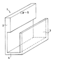
図12に示すように、従来、対向する側壁2及び3と、その側壁2及3をつなぐ底部4を有し、所定の長さの溝を構成するコンクリート製の基礎型枠1であって、一方の側壁2が他方の側壁3より上部に突出しており、該基礎型枠1を地中に埋設したとき、突出部2が所定の高さ地上に突出して、軽量コンクリートパネル(図示せず)を地上より離して支持することができるプレキャストコンクリート基礎型枠が公開されている。
As shown in FIG. 12, a concrete base formwork 1 having a
ここで、符号5は、埋込金具であり、上に載る軽量コンクリートパネルの下部固定の用をしている(例えば、特許文献1参照。)。
この基礎型枠1を使って鉄筋造建物の基礎を施工する場合は、まず、地盤を掘削して基礎の地中梁を設置する溝を掘り、溝の底面に砂利を敷き込んで平らに転圧した後、更に、底面を平らにするため、捨てコンクリートを打設し、硬化したのちに上記の基礎型枠1を地中梁の長さに合わせて複数個設置し、つぎに、鋼製梁を基礎型枠1の中に落とし込んだのち、コンクリートを打設するため、現場での作業が多岐にわたり、どうしても工期が長期化する。 When constructing the foundation of a reinforced building using this foundation formwork 1, first excavate the ground and dig a groove to install the foundation underground beam, lay gravel on the bottom of the groove and roll it flat. After pressing, in order to further flatten the bottom, cast concrete is placed and hardened, and then a plurality of the above-mentioned foundation molds 1 are installed according to the length of the underground beam, and then made of steel. After dropping the beam into the basic formwork 1 and placing concrete, the work at the site is diverse and the construction period is inevitably prolonged.
つまり、在来型枠工法は、次の(1)〜(9)の理由により、工期短縮にならないなどの問題があった。
(1)型枠大工、鉄筋工、アンカー工、土工などの多業社が必要である。(2)生コン打設のための配管が必要であり、型枠の移動などに余分な時間がかかる。(3)上記のうちの1業社が欠けても次の業社の作業に支障を来し、工期が把握し難く、不安である。(4)生コン打設のため、現場が汚い。(5)掃除代がかかる。(6)パネルなどの取り付けに埋込み金具が必要である。(7)不陸があるので、モルタル調整が必要である。(8)割高である。(9)型枠解体後、コンクリート強度が出るまで、次業社の施工ができない。
That is, the conventional formwork method has a problem that the construction period is not shortened for the following reasons (1) to (9).
(1) Multi-business companies such as formwork carpenters, reinforcing bars, anchors and earthwork are necessary. (2) Piping for raw concrete placement is required, and extra time is required for moving the formwork. (3) Even if one of the above companies is missing, the work of the next company will be hindered, and it will be difficult to grasp the construction period. (4) The site is dirty due to live-con placement. (5) A cleaning fee is required. (6) An embedded metal fitting is required for mounting a panel or the like. (7) Since there is unevenness, mortar adjustment is required. (8) It is expensive. (9) After dismantling the formwork, construction by the next company cannot be performed until the concrete strength is achieved.
本発明は、このような従来の問題を解消するためになされたものであり、その目的とするところは、現場での作業量を軽減し、省力化および工期の短縮を図ることができる基礎構造及びその施工方法を提供することにある。 The present invention has been made to solve such a conventional problem, and its object is to reduce the amount of work at the site, save labor and shorten the construction period. And providing a construction method thereof.
本発明は、上記の目的を達成するために、次のように構成されている。
請求項1に記載の発明に係る基礎構造は、基盤上に配置した複数個のブロックと、これらのブロック上に配置した金属製の長尺な通し部材と、前記基盤上に立設し、かつ、前記通し部材を前記ブロックに固定する複数本の締結部材より構成されている。
請求項2に記載の発明に係る基礎構造は、前記ブロックに外壁を取り付ける場合は、前記外壁を固定するための支持プレートを前記通し部材に一定の間隔で設ける。
請求項3に記載の発明に係る基礎構造は、前記通し部材に山形鋼を適用する。
請求項4に記載の発明に係る基礎構造は、前記ブロックに間仕切り壁を取り付ける場合は、前記通し部材に平形鋼を適用する。
請求項5に記載の発明に係る基礎構造は、前記ブロックにプレキャストコンクリートブロックを適用する。
請求項6に記載の発明に係る基礎構造の施工方法は、基盤上に複数個のブロックよりなる基礎構造を構築するに際し、(a)前記基盤を撥水剤混入モルタルなどのレベル調整材によりレベル調整し、(b)レベル調整後の基盤上に前記ブロックを1個ずつ配置し、(c)該ブロックの端部にある締結部材挿入部に対応する基盤部分にアンカーなどの固定部材を設置し、(d)該固定部材に締結部材を装着し、前記(a)〜(d)の作業を繰り返して所定長の基礎部分を構築し、続いて、前記基礎部分に金属製の長尺な通し部材を設置し、しかる後に、該通し部材を前記締結部材によって前記ブロックに固定する。
請求項7に記載の発明に係る基礎構造の施工方法は、基盤上に複数個のブロックよりなる基礎構造を構築するに際し、(a)前記基盤を撥水剤混入モルタルなどのレベル調整材によりレベル調整し、(b)レベル調整後の基盤上に前記ブロックを1個ずつ配置し、(c)該ブロックの端部にある締結部材挿入部に対応する基盤部分に締結部材を立設し、(d)該締結部材をヒルティなどの固定部材により前記基盤に固定し、前記(a)〜(d)の作業を繰り返して所定長の基礎部分を構築し、続いて、前記基礎部分に金属製の長尺な通し部材を設置し、しかる後に、該通し部材を前記締結部材によって前記ブロックに固定する。
In order to achieve the above object, the present invention is configured as follows.
The foundation structure according to the invention of claim 1 is provided with a plurality of blocks arranged on a base, a long metal through member arranged on these blocks, and standing on the base, and , And a plurality of fastening members for fixing the through member to the block.
In the basic structure according to the second aspect of the present invention, when an outer wall is attached to the block, a support plate for fixing the outer wall is provided on the through member at a constant interval.
In the basic structure according to the third aspect of the present invention, angle steel is applied to the through member.
In the basic structure according to the fourth aspect of the present invention, when attaching a partition wall to the block, flat steel is applied to the through member.
The foundation structure which concerns on invention of
In the construction method of the foundation structure according to the invention described in claim 6, when constructing the foundation structure composed of a plurality of blocks on the foundation, (a) the foundation is leveled by a level adjusting material such as a water repellent mixed mortar. (B) Place the blocks one by one on the base after level adjustment, and (c) install a fixing member such as an anchor on the base portion corresponding to the fastening member insertion portion at the end of the block. (D) A fastening member is attached to the fixing member, and the above-described steps (a) to (d) are repeated to construct a foundation portion having a predetermined length. Subsequently, a long metal piece is passed through the foundation portion. After the member is installed, the through member is fixed to the block by the fastening member.
In the construction method of the foundation structure according to the invention described in claim 7, when constructing a foundation structure composed of a plurality of blocks on the foundation, (a) the foundation is leveled by a level adjusting material such as a water repellent mixed mortar. Adjusting, (b) placing the blocks one by one on the base after level adjustment, (c) standing a fastening member on the base portion corresponding to the fastening member insertion portion at the end of the block, d) The fastening member is fixed to the base by a fixing member such as Hilti, and the steps (a) to (d) are repeated to construct a base portion having a predetermined length. Subsequently, the base portion is made of metal. A long threading member is installed, and then the threading member is fixed to the block by the fastening member.
請求項1に記載の発明に係る基礎構造は、基盤上に配置した複数個のブロックと、これらのブロック上に配置した金属製の長尺な通し部材と、前記基盤上に立設し、かつ、前記通し部材を前記ブロックに固定する複数本の締結部材より構成されているため、従来に比べて構造が簡単になり、現場での作業量が大幅に軽減する。このため、省力化および工期の短縮を図ることができる。 The foundation structure according to the invention of claim 1 is provided with a plurality of blocks arranged on a base, a long metal through member arranged on these blocks, and standing on the base, and Since it is composed of a plurality of fastening members for fixing the threading member to the block, the structure becomes simpler than before and the amount of work on site is greatly reduced. For this reason, it is possible to save labor and shorten the construction period.
更に、請求項1に記載の発明に係る基礎構造は、次のような効果がある。
(1)施工が1業社で足りる。(2)揚重がリフトでできる。(3)工期が掴め、予定数量の施工が可能てある。(4)生コン打設がないため、現場がきれいである。(5)掃除代がいらない。(6)ALCなどのパネル取付け下地が一発でできる。(7)不陸がないので、シール代を充分確保できる。(8)安価である。(9)PCブロック取り付け後、すぐに次業社の施工ができる。
Furthermore, the basic structure according to the first aspect of the present invention has the following effects.
(1) One company is sufficient for construction. (2) Lifting can be done by lift. (3) The construction period can be grasped and the planned quantity can be constructed. (4) The site is clean because there is no live concrete placement. (5) No cleaning fee is required. (6) A panel mounting base such as ALC can be formed in one shot. (7) Since there is no unevenness, a sufficient seal can be secured. (8) It is inexpensive. (9) After the PC block is installed, the construction of the next company can be performed immediately.
他方、請求項6に記載の発明に係る基礎構造の施工方法は、基盤上に複数個のブロックよりなる基礎構造を構築するに際し、(a)前記基盤を撥水剤混入モルタルなどのレベル調整材によりレベル調整し、(b)レベル調整後の基盤上に前記ブロックを1個ずつ配置し、(c)該ブロックの端部にある締結部材挿入部に対応する基盤部分にアンカーなどの固定部材を設置し、(d)該固定部材に締結部材を装着し、前記(a)〜(d)の作業を繰り返して所定長の基礎部分を構築し、続いて、前記基礎部分に金属製の長尺な通し部材を設置し、しかる後に、該通し部材を前記締結部材によって前記ブロックに固定するため、従来に比べて現場での作業量が大幅に減少する。このため、省力化および工期の短縮を図ることができる。 On the other hand, in the construction method of the foundation structure according to the invention described in claim 6, when constructing a foundation structure composed of a plurality of blocks on the base, (a) the base is made of a level adjusting material such as a water repellent mixed mortar. (B) The blocks are arranged one by one on the base after level adjustment, and (c) a fixing member such as an anchor is attached to the base portion corresponding to the fastening member insertion portion at the end of the block. And (d) attaching a fastening member to the fixing member, constructing a base portion having a predetermined length by repeating the operations (a) to (d), and subsequently forming a metal long piece on the base portion. Since a threading member is installed and then the threading member is fixed to the block by the fastening member, the amount of work at the site is greatly reduced compared to the prior art. For this reason, it is possible to save labor and shorten the construction period.
更に、請求項6に記載の発明に係る基礎構造の施工方法は、次のような効果がある。
(1)施工が1業社で足りる。(2)揚重がリフトでできる。(3)工期が掴め、予定数量の施工が可能てある。(4)生コン打設がないため、現場がきれいである。(5)掃除代がいらない。(6)ALCなどのパネル取付け下地が一発でできる。(7)不陸がないので、シール代を充分確保できる。(8)安価である。(9)PCブロック取り付け後、すぐに次業社の施工ができる。
Furthermore, the foundation construction method according to the invention of claim 6 has the following effects.
(1) One company is sufficient for construction. (2) Lifting can be done by lift. (3) The construction period can be grasped and the planned quantity can be constructed. (4) The site is clean because there is no live concrete placement. (5) No cleaning fee is required. (6) A panel mounting base such as ALC can be formed in one shot. (7) Since there is no unevenness, a sufficient seal can be secured. (8) It is inexpensive. (9) After the PC block is installed, the construction of the next company can be performed immediately.
また、請求項7に記載の発明に係る基礎構造の施工方法は、基盤上に複数個のブロックよりなる基礎構造を構築するに際し、(a)前記基盤を撥水剤混入モルタルなどのレベル調整材によりレベル調整し、(b)レベル調整後の基盤上に前記ブロックを1個ずつ配置し、(c)該ブロックの端部にある締結部材挿入部に対応する基盤部分に締結部材を立設し、(d)該締結部材をヒルティなどの固定部材により前記基盤に固定し、前記(a)〜(d)の作業を繰り返して所定長の基礎部分を構築し、続いて、前記基礎部分に金属製の長尺な通し部材を設置し、しかる後に、該通し部材を前記締結部材によって前記ブロックに固定するため、従来に比べて現場での作業量が大幅に減少する。このため、省力化および工期の短縮を図ることができる。 In addition, when the foundation structure construction method according to the invention of claim 7 is used to construct a foundation structure composed of a plurality of blocks on the base, (a) the base is made of a level adjusting material such as a mortar mixed with a water repellent. (B) The blocks are arranged one by one on the base after level adjustment, and (c) the fastening member is erected on the base portion corresponding to the fastening member insertion portion at the end of the block. (D) The fastening member is fixed to the base by a fixing member such as Hilti, and the steps (a) to (d) are repeated to construct a base portion having a predetermined length, and then the base portion is made of metal. Since a long through member made of metal is installed, and then the through member is fixed to the block by the fastening member, the amount of work on site is greatly reduced compared to the conventional case. For this reason, it is possible to save labor and shorten the construction period.
更に、請求項7に記載の発明に係る基礎構造の施工方法は、次のような効果がある。
(1)施工が1業社で足りる。(2)揚重がリフトでできる。(3)工期が掴め、予定数量の施工が可能てある。(4)生コン打設がないため、現場がきれいである。(5)掃除代がいらない。(6)ALCなどのパネル取付け下地が一発でできる。(7)不陸がないので、シール代を充分確保できる。(8)安価である。(9)PCブロック取り付け後、すぐに次業社の施工ができる。
Furthermore, the foundation construction method according to the invention of claim 7 has the following effects.
(1) One company is sufficient for construction. (2) Lifting can be done by lift. (3) The construction period can be grasped and the planned quantity can be constructed. (4) The site is clean because there is no live concrete placement. (5) No cleaning fee is required. (6) A panel mounting base such as ALC can be formed in one shot. (7) Since there is no unevenness, a sufficient seal can be secured. (8) It is inexpensive. (9) After the PC block is installed, the construction of the next company can be performed immediately.
以下、本発明の実施の形態を図面を用いて説明する。
まず、外壁取付け用の基礎構造について説明し、続いて、間仕切り取付け用の基礎構造について説明する。
Hereinafter, embodiments of the present invention will be described with reference to the drawings.
First, the foundation structure for attaching the outer wall will be described, and then the foundation structure for attaching the partition will be explained.
(1)外壁取付け用の基礎構造について
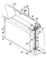
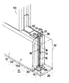
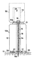
図1において、10aは、外壁取付け用の基礎構造であり、コンクリートを打設した基盤11上に直線状に敷き込んだ複数個のPCブロック(プレキャストコンクリートブロック)12と、これらのPCブロック12の上に配置した長尺な山形鋼13aと、前記基盤11上に立設し、かつ、前記山形鋼13aを前記PCブロック12に固定する複数本の締結部材14により構成されている。この締結部材14は、締結ボルト15及び締結ナット16により構成されている。
(1) Foundation structure for attaching the outer wall In FIG. 1,
この締結ボルト15は、PCブロック12の両端面に設けられている溝状の締結部材挿入部18が合体することによって形成された縦穴28内に設けられている。その上、この締結ボルト15は、その下端部に設けたアンカーなどの固定部材19aを用いて基盤11に固定されている。
The
PCブロック12と山形鋼13aとの間には、2枚のプレート21及び22が設けられ、締結ナット16の下には、ワッシャ23が設けられている。上記の縦穴28には、所望により、撥水剤混入モルタルなどの充填材を充填する。
Two
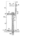
また、山形鋼13aには、一定の間隔で支持プレート(イナズマプレート)24を取り付け、基礎構造10a上に設置したプレキャストコンクリートブロック製の外壁40を固定する。その際、図2に示すように、外壁40に埋設した埋設金具41と支持プレート24とをボルト25によって結合する。
In addition, a support plate (inazuma plate) 24 is attached to the
図1及び図2に示すように、PCブロック12を設置する鉄筋コンクリート製の基盤11の部分は、撥水剤混入モルタル20によってレベル調整されている。
図中、符号26はアンカー鋼棒、27はバックアップ材、29はシーリング材、30はPCブロック12のつなぎ目に設けたシーリング材充填溝である。
As shown in FIGS. 1 and 2, the level of the portion of the reinforced
In the figure,
続いて、上記の基礎構造の施工方法を図3乃至図7を用いて説明する。
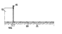
(a) まず、図3に示すように、鉄筋コンクリート製の基盤11の表面を撥水剤混入モルタル20によりレベル調整する。
図3中、符号12は既に基盤11上に敷き込んだPCブロック、15は締結ボルト、19aはアンカーである。
Subsequently, the construction method of the above-described foundation structure will be described with reference to FIGS.
(A) First, as shown in FIG. 3, the level of the surface of the base 11 made of reinforced concrete is adjusted with a
In FIG. 3,
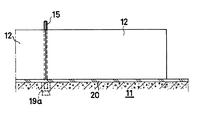
(b) 次に、図4に示すように、レベル調整後の基盤11上にPCブロック12を1個敷き込む。
(B) Next, as shown in FIG. 4, one
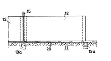
(c) 次に、図5に示すように、敷き込み直後のPCブロック12の先端面にある溝状の固定部材挿入部18に対応する基盤部分にアンカー19aを打ち込む。
(C) Next, as shown in FIG. 5, an
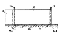
(d) 次に、図6に示すように、基盤11に打ち込んだアンカー19aに締結ボルト15を装着する。
(D) Next, as shown in FIG. 6, the
(e) 次に、上記(a)〜(d)の作業を繰り返し行って所定長の基礎部分を構築する。 (E) Next, the above-described operations (a) to (d) are repeatedly performed to construct a basic portion having a predetermined length.
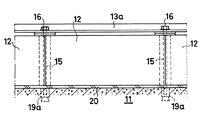
(f) 続いて、図7に示すように、上記基礎部分の上に山形鋼13aを配置した後、山形鋼13aを締結ナット16よってPCブロック12に固定する。
(F) Subsequently, as shown in FIG. 7, after the
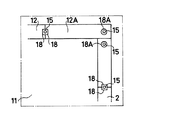
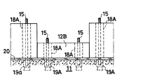
ところで、図8に示すように、基礎構造10aのコーナー部分に使用するPCブロック12Aは、一方の締結部材挿入部18Aが孔状になっており、その中に締結ボルト15を挿入するようになっている。
また、図9に示すように、ドアなどを設置する開口下の部分のPCブロック12Bは、その両側にそれぞれ孔状の締結部材挿入部18Aを設ける。
By the way, as shown in FIG. 8, the PC block 12A used for the corner portion of the
Further, as shown in FIG. 9, the
(2)間仕切り取付け用の基礎構造について
次に、間仕切り取付け用基礎構造10bについて説明するが(図10及び図11参照。)、外壁取付け用基礎構造10aと同じ部材には同じ符号を付け、詳しい説明については省略する。
(2) About the base structure for partition mounting Next, the
両者は、非常に良く似ているが、外壁取付け用基礎構造10aでは、通し部材として山形鋼13aを用いているのに対し、間仕切り取付け用基礎構造10bでは、通し部材に平形鋼13bを使用している点が相違する。また、外壁取付け用基礎構造10aでは、外壁40をボルト止めしているのに対し、間仕切り取付け用基礎構造10bでは、プレキャストコンクリート製の間仕切り50に設けたL形プレート51を平形鋼13bに溶接止めしている。符号52は溶接部分を示している。
They are very similar, but the outer wall mounting
また、両者の施工方法も類似しているが、間仕切り取付け用基礎構造10bを施工する場合は、PCブロック12の溝状の締結部材挿入部18に対応する基盤部分に締結ボルト15を立設し、しかる後に、締結ボルト15の下端部に設けた支持板17をヒルティなどの固定部材19bによって基盤11に固定する点が異なっている。
Moreover, both construction methods are similar, but when constructing the partition mounting
本発明の基礎構造およびその施工方法は、あらゆるコンクリート構造物の施工に用いることができる。 The foundation structure and its construction method of the present invention can be used for construction of any concrete structure.
11 基盤
12 ブロック
13a,13b 通し部材
14 締結部材
11
Claims (7)
When constructing a foundation structure composed of a plurality of blocks on the base, (a) the base is level-adjusted with a level adjusting material such as a water repellent mixed mortar, and (b) the block is placed on the base after level adjustment. One by one, (c) a fastening member is erected on the base portion corresponding to the fastening member insertion portion at the end of the block, and (d) the fastening member is fixed to the base by a fixing member such as Hilti Then, the above-described operations (a) to (d) are repeated to construct a foundation portion having a predetermined length, and subsequently, a metal long threading member is installed in the foundation portion. The construction method of the foundation structure fixed to the block by the fastening member.
Priority Applications (1)
| Application Number | Priority Date | Filing Date | Title |
|---|---|---|---|
| JP2004120332A JP2005299318A (en) | 2004-04-15 | 2004-04-15 | Foundation structure and its execution method |
Applications Claiming Priority (1)
| Application Number | Priority Date | Filing Date | Title |
|---|---|---|---|
| JP2004120332A JP2005299318A (en) | 2004-04-15 | 2004-04-15 | Foundation structure and its execution method |
Publications (1)
| Publication Number | Publication Date |
|---|---|
| JP2005299318A true JP2005299318A (en) | 2005-10-27 |
Family
ID=35331200
Family Applications (1)
| Application Number | Title | Priority Date | Filing Date |
|---|---|---|---|
| JP2004120332A Pending JP2005299318A (en) | 2004-04-15 | 2004-04-15 | Foundation structure and its execution method |
Country Status (1)
| Country | Link |
|---|---|
| JP (1) | JP2005299318A (en) |
Cited By (1)
| Publication number | Priority date | Publication date | Assignee | Title |
|---|---|---|---|---|
| JP2008013919A (en) * | 2006-07-03 | 2008-01-24 | Tsuneo Takaishi | Rising foundation member for wall base |
Citations (6)
| Publication number | Priority date | Publication date | Assignee | Title |
|---|---|---|---|---|
| JPH03187447A (en) * | 1989-12-14 | 1991-08-15 | Natl House Ind Co Ltd | Structure of external wall |
| JPH07207822A (en) * | 1994-01-25 | 1995-08-08 | Tokyu Koken Kk | Joint method of precast reinforced concrete member |
| JPH07324403A (en) * | 1994-05-31 | 1995-12-12 | Natl House Ind Co Ltd | External wall panel position adjusting method |
| JPH10169020A (en) * | 1996-12-12 | 1998-06-23 | Onoda Autoclaved Light Weight Concrete Co Ltd | Mounting structure for acl panel on continuous footing |
| JPH11166239A (en) * | 1997-12-04 | 1999-06-22 | Sekisui House Ltd | Connection structure of assembly foundation |
| JP2004100265A (en) * | 2002-09-10 | 2004-04-02 | Hitoshi Mori | Connecting structure of pc continuous footing member and method of constructing continuous footing using pc continuous footing member |
-
2004
- 2004-04-15 JP JP2004120332A patent/JP2005299318A/en active Pending
Patent Citations (6)
| Publication number | Priority date | Publication date | Assignee | Title |
|---|---|---|---|---|
| JPH03187447A (en) * | 1989-12-14 | 1991-08-15 | Natl House Ind Co Ltd | Structure of external wall |
| JPH07207822A (en) * | 1994-01-25 | 1995-08-08 | Tokyu Koken Kk | Joint method of precast reinforced concrete member |
| JPH07324403A (en) * | 1994-05-31 | 1995-12-12 | Natl House Ind Co Ltd | External wall panel position adjusting method |
| JPH10169020A (en) * | 1996-12-12 | 1998-06-23 | Onoda Autoclaved Light Weight Concrete Co Ltd | Mounting structure for acl panel on continuous footing |
| JPH11166239A (en) * | 1997-12-04 | 1999-06-22 | Sekisui House Ltd | Connection structure of assembly foundation |
| JP2004100265A (en) * | 2002-09-10 | 2004-04-02 | Hitoshi Mori | Connecting structure of pc continuous footing member and method of constructing continuous footing using pc continuous footing member |
Cited By (1)
| Publication number | Priority date | Publication date | Assignee | Title |
|---|---|---|---|---|
| JP2008013919A (en) * | 2006-07-03 | 2008-01-24 | Tsuneo Takaishi | Rising foundation member for wall base |
Similar Documents
| Publication | Publication Date | Title |
|---|---|---|
| KR101277751B1 (en) | Precast Concrete Blocks and Remodeling Reinforcing Construction Methods for Low and Middle-rise Beam-column Buildings by Using that Blocks | |
| CN205296584U (en) | Be applied to assembled constructional column of aerated concrete block infilled wall | |
| KR20080100740A (en) | Reverse support structure of mud wall using open type plate for continuous construction of underground plywood and continuous construction method of underground plywood using the same | |
| JP4190360B2 (en) | Masonry wall reinforcement structure and method | |
| JP5503408B2 (en) | Building construction method | |
| JP3682588B2 (en) | Building member connection structure of H-shaped steel continuous foundation beam | |
| CN210263417U (en) | Structure of bearing node is connected with girder steel to translation formula precast concrete externally-hung wallboard | |
| CN106988298A (en) | The concrete guide wall and its construction method of a kind of preset reinforcing bar of assembled | |
| JP3185129B2 (en) | Column-integrated column base fixed foundation structure and its construction method | |
| JP4228308B2 (en) | Reinforcement method for existing floors and seismic isolation method for existing buildings | |
| KR100962001B1 (en) | Construction Structure and Construction Method of Finished Reinforced Concrete Wall | |
| KR20010019079A (en) | Precast steel Plate &Concrete Pile Structure of Semi Down Wall Construction System | |
| JP4460357B2 (en) | Construction method of underground concrete structure | |
| JPH09203053A (en) | Precast reinforced concrete foundation structure | |
| CN210263565U (en) | Additional building type floor slab in later period of decoration | |
| JP5270255B2 (en) | Foundation reinforcement method for existing wooden houses | |
| KR200194424Y1 (en) | Precast retaining wall using high strength micro pile | |
| JP4511080B2 (en) | Construction method of underground structure | |
| KR100590178B1 (en) | Formwork fixture for earth wall | |
| CN110761558A (en) | Basement outer wall unilateral template strutting arrangement | |
| JP7792083B2 (en) | Unit structure and unit structure construction method | |
| JP3010556B1 (en) | Fixing method of precast concrete formwork to underground concrete connecting wall | |
| JP2014173305A (en) | Arc form and structure of retaining wall | |
| JP6393352B2 (en) | Repair method for existing waterways | |
| RU2368742C1 (en) | Method for manufacturing of wall-ceiling structure in reinforced concrete version |
Legal Events
| Date | Code | Title | Description |
|---|---|---|---|
| A621 | Written request for application examination |
Free format text: JAPANESE INTERMEDIATE CODE: A621 Effective date: 20070405 |
|
| A977 | Report on retrieval |
Free format text: JAPANESE INTERMEDIATE CODE: A971007 Effective date: 20091013 |
|
| A131 | Notification of reasons for refusal |
Free format text: JAPANESE INTERMEDIATE CODE: A131 Effective date: 20091021 |
|
| A02 | Decision of refusal |
Free format text: JAPANESE INTERMEDIATE CODE: A02 Effective date: 20100303 |