JP2005299721A - Automobile ball screw - Google Patents
Automobile ball screw Download PDFInfo
- Publication number
- JP2005299721A JP2005299721A JP2004112894A JP2004112894A JP2005299721A JP 2005299721 A JP2005299721 A JP 2005299721A JP 2004112894 A JP2004112894 A JP 2004112894A JP 2004112894 A JP2004112894 A JP 2004112894A JP 2005299721 A JP2005299721 A JP 2005299721A
- Authority
- JP
- Japan
- Prior art keywords
- screw
- ball
- nut
- shaft
- ball screw
- Prior art date
- Legal status (The legal status is an assumption and is not a legal conclusion. Google has not performed a legal analysis and makes no representation as to the accuracy of the status listed.)
- Pending
Links
- 238000005096 rolling process Methods 0.000 claims abstract description 24
- 238000004826 seaming Methods 0.000 claims description 13
- 230000004323 axial length Effects 0.000 claims description 8
- 241001661918 Bartonia Species 0.000 abstract 4
- 238000005242 forging Methods 0.000 abstract 2
- 230000005540 biological transmission Effects 0.000 description 11
- 238000000034 method Methods 0.000 description 5
- 230000000694 effects Effects 0.000 description 4
- 230000033001 locomotion Effects 0.000 description 3
- 230000007246 mechanism Effects 0.000 description 3
- 230000008878 coupling Effects 0.000 description 2
- 238000010168 coupling process Methods 0.000 description 2
- 238000005859 coupling reaction Methods 0.000 description 2
- 238000005336 cracking Methods 0.000 description 2
- 235000013372 meat Nutrition 0.000 description 2
- 230000002093 peripheral effect Effects 0.000 description 2
- 238000005097 cold rolling Methods 0.000 description 1
- 238000002788 crimping Methods 0.000 description 1
- 238000009499 grossing Methods 0.000 description 1
- 230000006872 improvement Effects 0.000 description 1
- 238000004519 manufacturing process Methods 0.000 description 1
- 238000003825 pressing Methods 0.000 description 1
- 230000008569 process Effects 0.000 description 1
- 230000009467 reduction Effects 0.000 description 1
Images


Landscapes
- Transmission Devices (AREA)
Abstract
Description
この発明は、電動パワーステアリング装置や、自動マニュアルトランスミッション(AMT)等のアクチュエータに使用される自動車用ボールねじに関する。 The present invention relates to a ball screw for an automobile used for an actuator such as an electric power steering device and an automatic manual transmission (AMT).
従来、ボールねじにおいて、ねじ軸のねじ溝の肩部に、断面円弧状の面取部を設けたものが提案されている(例えば、特許文献1)。これは、高速時にねじ溝肩部に衝突しながらボールが循環するときに、損傷を生じ易くなることを回避し、長寿命化を図るものである。
上記の従来例は、工作機械、一般産業機械に用いられるボールねじにおいて、機械の高速化が進んでいることにより、その高速運転時に要求される特性に対してなされた工夫である。
自動車用ボールねじの用途においては、高速運転される工作機械,一般産業機械とは異なった特性が求められている。すなわち、電動パワーステアリング等の人の手によって直接に操作される装置においては、その操舵感を損なわないように、トルク変動の少ない作動が要求される。また、自動マニュアルトランスミッション(AMT)や、電動ブレーキ等のアクチュエータとして用いられる場合は、電子制御との親和性、あるいはより大きな推力を得るための、高い効率、つまり機械損失のないものであることが求められる。
また、自動車用のボールねじでは、安全性が強く要望され、さらに低コスト化のために生産性に優れたものであることが求められる。
The above-described conventional example is a device made for the characteristics required during high-speed operation of a ball screw used in a machine tool or a general industrial machine due to an increase in the speed of the machine.
In the application of ball screws for automobiles, characteristics different from those of machine tools and general industrial machines that are operated at high speed are required. That is, an apparatus that is directly operated by a human hand such as an electric power steering is required to operate with little torque fluctuation so as not to impair the steering feeling. In addition, when used as an actuator such as an automatic manual transmission (AMT) or an electric brake, it must be compatible with electronic control or have a high efficiency for obtaining a larger thrust, that is, no mechanical loss. Desired.
In addition, the ball screw for automobiles is strongly demanded for safety, and is further required to have excellent productivity for cost reduction.
この発明の目的は、ボールの循環が滑らかで、トルク変動が少なく、伝達効率にも優れていて、強度、および生産性にも優れた自動車用ボールねじを提供することである。 An object of the present invention is to provide a ball screw for an automobile in which the circulation of the ball is smooth, the torque fluctuation is small, the transmission efficiency is excellent, the strength and the productivity are excellent.
この発明の自動車用ボールねじは、自動車用アクチュエータに使用されるボールねじであって、ボールを転走させるねじ溝が対向して形成されたねじ軸およびナットと、前記対向するねじ溝間に介在した複数のボールとを備え、前記ねじ軸のねじ溝が転造加工されたものであり、前記ねじ軸のねじ溝の内面がねじ軸外径面に続く肩部に、断面円弧状の面取部が前記転造加工により形成されたことを特徴とする。 The automotive ball screw of the present invention is a ball screw used in an automotive actuator, and is interposed between a screw shaft and a nut in which screw grooves for rolling the ball are opposed to each other, and the opposed screw grooves. And a thread groove of the screw shaft is formed by rolling, and a chamfer having an arc-shaped cross section is formed on a shoulder portion where the inner surface of the screw groove of the screw shaft is continuous with the outer surface of the screw shaft. The portion is formed by the rolling process.
この構成の自動車用ボールねじによると、ねじ軸のねじ溝の肩部に断面円弧状の面取部が形成されているため、ねじ溝間のランド部を乗り超えてボールが循環するときのボールの循環が滑らかで、トルク変動が少なく、伝達効率にも優れたものとなる。上記面取部が設けられていると、ノイズレベルも低下するため、例えば電動パワーステアリング装置等のように音響特性が求められる自動車用の用途において、その要求特性に応じたものとできる。
また、このねじ軸は転造加工によるため、生産性に優れている。この場合に、ロールダイスによる冷間転造加工を行うため、ロールダイスの、ねじ軸製品としてねじ溝肩部に相当する部分に断面円弧状の部分を設けておくことで、ねじ溝肩部の断面円弧状の面取部が形成される。このように、ロールダイスに断面円弧状の部分を設けておいて、ねじ溝と同時に肩部の面取部を転造加工することは、ねじ軸のねじ溝となる部分の材料を塑性流動させ、肉が盛り上がってきた場合に、局部的な力の集中を防止し、割れの防止、あるいはスプリングバック量を小さくして精度良く加工するためにも有効である。この転造加工法により、ねじ軸のねじ溝肩部に容易に任意寸法の円弧状面取部を形成することが可能であるため、自動車用ボールねじのねじ軸の加工においては、上記の転造加工が、生産性向上によるコスト面、性能面の両方から適している。
According to the ball screw for automobiles of this configuration, since the chamfered portion having a circular cross section is formed on the shoulder portion of the screw groove of the screw shaft, the ball is circulated over the land portion between the screw grooves. Circulation is smooth, torque fluctuation is small, and transmission efficiency is excellent. If the chamfered portion is provided, the noise level is also reduced. Therefore, for example, in an automobile application where acoustic characteristics are required, such as an electric power steering device, the required characteristics can be satisfied.
Moreover, since this screw shaft is formed by rolling, it is excellent in productivity. In this case, in order to perform a cold rolling process using a roll die, by providing an arc-shaped section in a portion corresponding to the thread groove shoulder as a screw shaft product of the roll die, A chamfered portion having an arcuate cross section is formed. Thus, by providing a roll die with an arc-shaped section and rolling the chamfered portion of the shoulder at the same time as the thread groove, the material of the thread groove portion of the screw shaft is plastically flowed. When the meat swells, it is effective for preventing local concentration of force, preventing cracking, or reducing the amount of spring back and processing with high accuracy. By this rolling method, it is possible to easily form an arc-shaped chamfered portion of an arbitrary size on the shoulder of the screw groove of the screw shaft. Manufacturing is suitable for both cost and performance due to improved productivity.
この成形性と、実際のボールねじを回転させた場合の作動性を考慮した場合、前記円弧状の面取部の曲率半径が、ボールの半径の2.5〜25%の範囲であることが好ましい。25%を超えると、ボールが押し付けられることで生じるねじ溝内面の応力発生範囲である接触楕円が、ねじ溝の面取部に干渉する量が増加し、短寿命を引き起こす可能性がある。また、2.5%未満であると、面取部が小さ過ぎて、面取部を設けたことによる各種の効果が十分に得られない。 In consideration of this formability and operability when an actual ball screw is rotated, the radius of curvature of the arc-shaped chamfered portion may be in the range of 2.5 to 25% of the radius of the ball. preferable. If it exceeds 25%, the contact ellipse, which is the stress generation range of the inner surface of the thread groove generated by pressing the ball, increases the amount of interference with the chamfered portion of the thread groove, which may cause a short life. On the other hand, if it is less than 2.5%, the chamfered portion is too small, and various effects obtained by providing the chamfered portion cannot be sufficiently obtained.
また、転造加工されるねじ軸を使用する場合、そのランド部の材料不充足部分であるシーミング部の形状管理が不可欠である。シーミング部が大きいと、ランド部をボールが乗り超えるときに、ボールが落ち込むことがあり、その円滑な作動が妨げられる。したがって、面取部を設けるだけでなく、シーミング部の寸法を管理することが重要である。このシーミング部は、ランド部の軸方向長さの1/2以下とすることで、滑らかなボールの動作が得られる。 In addition, when using a threaded shaft that is rolled, it is indispensable to manage the shape of the seaming portion that is the material unsatisfied portion of the land portion. If the seaming part is large, the ball may fall when the ball gets over the land part, and the smooth operation is hindered. Therefore, it is important not only to provide a chamfered portion but also to manage the dimensions of the seaming portion. By making the seaming portion ½ or less of the axial length of the land portion, a smooth ball motion can be obtained.
この発明の自動車用ボールねじは、循環形式が駒式である場合、つまりナットのねじ溝同士を連結する駒部材を設けたものである場合に、特に、上記各効果が有効となる。
自動車用ボールねじにおいては、循環方式として、ナットのコンパクト性や、ナット回転時に循環部が等配列にできる特長があることから、駒式が採用されることが多い。この循環方式は、ボールが循環するときに、ねじ軸のランド部上を、駒内の空間で拘束されながら乗り超えて循環する形式である。このため、ねじ軸のねじ溝の肩部に断面円弧状の面取部を設けたことや、シーミング部の寸法を1/2以下にすることによる円滑化等の効果が有効に発揮される。
The above-mentioned effects are particularly effective when the circulation type of the automobile ball screw according to the present invention is a piece type, that is, when a piece member that connects screw grooves of nuts is provided.
In the ball screw for automobiles, a piece type is often adopted as a circulation method because of the compactness of the nut and the feature that the circulation part can be arranged in the same manner when the nut rotates. In this circulation method, when the ball circulates, it circulates over the land portion of the screw shaft while being constrained by the space in the piece. For this reason, effects such as smoothing by effectively providing a chamfered portion having an arcuate cross section at the shoulder portion of the thread groove of the screw shaft and reducing the dimension of the seaming portion to 1/2 or less are effectively exhibited.
この発明の自動車用ボールねじは、自動車用アクチュエータに使用されるボールねじであって、前記ねじ軸のねじ溝が転造加工されたものであり、前記ねじ軸のねじ溝の内面がねじ軸外径面へ続く肩部に、断面円弧状の面取部が前記転造加工により形成されたものであるため、ボールの循環が滑らかで、トルク変動が少なく、伝達効率にも優れていて、強度、および生産性にも優れたものとなる。 The automotive ball screw according to the present invention is a ball screw used for an automotive actuator, wherein the threaded groove of the threaded shaft is rolled, and the inner surface of the threaded groove of the threaded shaft is outside the threaded shaft. Since the chamfered portion with a circular arc cross section is formed by the rolling process on the shoulder that continues to the radial surface, the ball circulation is smooth, torque fluctuation is small, transmission efficiency is excellent, and strength , And productivity is also excellent.
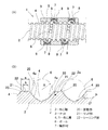
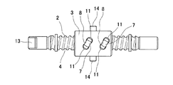
この発明の第1の実施形態を図1ないし図5と共に説明する。このボールねじ1は、自動車用のアクチュエータに使用される駒式のボールねじであって、ねじ軸2およびナット3と、これらねじ軸2およびナット3の対向面に形成されたねじ溝4,5間に介在するボール6とでなる。ねじ溝4,5は、ボール6を転走される螺旋状の溝である。この実施形態の自動車用ボールねじ1を使用する自動車用アクチュエータは、自動車の自動マニュアルトランスミッション(AMT)に使用されるものであるが、この他に、電動パワーステアリング、後輪操舵装置、自動車用電動ブレーキ等に使用されるものであって良い。
A first embodiment of the present invention will be described with reference to FIGS. This ball screw 1 is a piece type ball screw used for an actuator for an automobile, and includes a
ナット3は、ボール6の循環用の部品として駒部材7が設けられている。駒部材7は、ナット3に内外面に貫通して形成された嵌合用開口8に嵌合し、ナット3の螺旋状のねじ溝5の隣合う各周の部分同士を連結する1条の連結溝9を内面に形成した部材である。この連結溝9により、ねじ軸2とナット3のねじ溝4,5間で形成される螺旋条のボール転走路が周回経路となり、ボール6がこの周回経路を循環移動する。ボール6は、連結溝9を通過するときは、ねじ軸2のねじ溝4のねじ山を乗り超えることになる。
The
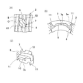
図4に示すように、駒部材7は、ナット3のねじ溝5に係合する一対のウイング部10を有し、かつナット3の外径部に固定される一対の加締部11を有している。これらウイング部10の内径側からの係合と加締部11の外径側からの加締によって、駒部材7はナット3に固定される。
As shown in FIG. 4, the
図3に示すように、ナット3は、外周面に一対のトラニオン軸部14を有している。ねじ軸2は、一端にカップリング嵌合部13を有し、他端に軸受嵌合部15が設けられている。
As shown in FIG. 3, the
このような駒式の自動車用ボールねじ1において、この実施形態では、ねじ軸2のねじ溝4が転造加工されたものとされる。また、図1(B)に拡大して示すように、ねじ軸2のねじ溝4の内面4aがねじ軸外径面2aへ続く肩部に、断面円弧状の面取部20を前記ねじ溝4の転造加工により同時に形成する。
In such a piece-type automotive ball screw 1, in this embodiment, the
面取部20の曲率半径rは、ボール6の半径Rの2.5〜25%の範囲とする。ねじ軸2の隣合うねじ溝4間の外径面2aからなるランド部21には、転造加工により材料の不充足部分である円周溝状のシーニング部22が生じる。このシーニング部22の軸方向長さbは、ランド部21の軸方向長さaの1/2以下とする。
ランド部21の軸方向長さは、面取部20が設けられているため、面取部20を無しとした場合の長さとなる。また、シーニング部22の軸方向長さbは、ランド部21の外径面よりも凹みが生じ始める位置の間の長さである。
The curvature radius r of the
Since the chamfered
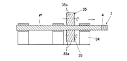
ねじ軸2のねじ溝4の転造加工は、図5に示すように、支持台34に回転および進退自在に支持された丸棒状の素材Wを、一対のロールダイス35の間に挟み込み、ロールダイス35を回転させることにより行う。ロールダイス35は、外周面に転造用の多条の螺旋条突条35aを有するものである。
図1のねじ溝4の断面円弧状の面取部20は、図6に示すように、上記ロールダイス35に、面取部20と対応する断面円弧状の型部35bを設けておくことにより、ねじ溝4と同時に転造加工される。
As shown in FIG. 5, the rolling process of the
As shown in FIG. 6, the chamfered
この構成の自動車用ボールねじ1によると、ねじ軸2のねじ溝4の肩部に断面円弧状の面取部20が形成されているため、ランド部20を乗り超えてボール6が循環するときのボール6の循環が滑らかで、トルク変動が少なく、伝達効率にも優れたものとなる。すなわち、ボール6は駒部材7を通過するときに、駒部材7の連結溝9内に拘束されながらランド部20上を、乗り超えて循環することになる。この循環時のボール6の動作が面取部20によって円滑に行われる。面取部20が設けられていると、ノイズレベルも低下するため、例えば電動パワーステアリング装置等のように音響特性が求められる自動車用の用途において、その要求特性に応じたものとできる。
According to the ball screw 1 for an automobile having this configuration, since the chamfered
また、このねじ軸2は転造加工によるため、生産性に優れている。この場合に、ロールダイス35にねじ軸製品のねじ溝肩部に相当する部分に上記断面円弧状の型部35b(図6)を設けておくことで、ねじ溝4と同時に面取部20が形成される。このように、ロールダイス35に断面円弧状の型部35bを設けておいて、ねじ溝4と同時に肩部の面取部20を転造加工することは、ねじ軸2のねじ溝4となる部分の材料を塑性流動させ、肉が盛り上がってきた場合に、局部的な力の集中を防止し、割れの防止、あるいはスプリングバック量を小さくして精度良く加工するためにも有効である。
この転造加工法により、ねじ軸2のねじ溝肩部に容易に任意寸法の円弧状面取部20を形成することが可能であるため、自動車用ボールねじ1のねじ軸2の加工においては、上記の転造加工が、性能面、生産性向上によるコスト面の両方から適している。
Moreover, since this
By this rolling method, it is possible to easily form an arc-shaped chamfered
この成形性と、実際のボールねじ1を回転させた場合の作動性を考慮した場合、面取部20の曲率半径rは、ボール6の半径Rの2.5〜25%の範囲であることが好ましい。25%を超えると、ボール6が押し付けられることで生じるねじ溝内面の応力発生範囲である接触楕円Pが、ねじ溝4の面取部20に干渉する量が増加し、短寿命を引き起こす可能性がある。また、2.5%未満であると、面取部20が小さ過ぎて、面取部20を設けたことによる各種の効果が十分に得られない。
In consideration of this formability and the operability when the actual ball screw 1 is rotated, the radius of curvature r of the chamfered
また、転造加工されるねじ軸2を使用する場合、そのランド部21の不充足部分であるシーミング部22の形状管理が不可欠である。シーミング部22が大きいと、ランド部21をボール6が乗り超えるときに、ボール6が落ち込むことがあり、その円滑な作動が妨げられる。したがって、面取部20を設けるだけでなく、シーミング部22の寸法を管理することが重要である。このシーミング部22は、ランド部21の軸方向長さaの1/2以下とすることで、滑らかなボール6の動作が得られる。
In addition, when using the threaded
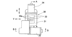
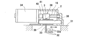
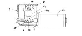
図7〜図9は、この実施形態に係るボールねじ1を使用した自動マニュアルトランスミッション(AMT)におけるシフト機構の一例を示す。このシフト機構30は、ハウジング31内に複数本平行に設置された進退自在な任意のシフトレール32を、その長手方向(Y方向)に移動させることで、シフト動作、つまり変速ギヤ(図示せず)の切換を行うものである。各シフトレール32は、切欠32aを有していて、図8のシフトフィンガ33が係合可能である。このシフトフィンガ33の係脱により、進退動作させるシフトレール32が選択される。
7 to 9 show an example of a shift mechanism in an automatic manual transmission (AMT) using the ball screw 1 according to this embodiment. The
シフトフィンガ33を上記選択のために進退させるを動作に、第1のモータ34および第1のボールねじ36が用いられる。また、シフトフィンガ33を揺動させてシフトレール32を進退させる動作に、図9の第2のモータ35および第2のボールねじ37が用いられる。これら第1および第2のボールねじ36,37に、上記実施形態の自動車用ボールねじ1が用いられる。ただし、第1のボールねじ36は、そのナット3につき、トラニオン軸部14がなく、係合溝16が設けられたものとする。
The
図8において、ハウジング31に第1のシャフト部材38が進退自在に設置され、その外周にスリーブ39が進退のみ自在に嵌合している。スリーブ39は、第1のシャフト38と一体に回動が可能である。このスリーブ39に、上記シフトフィンガ34が設けられている。第1のシャフト部材38と平行に、第1のボールねじ36のねじ軸2が配置されてハウジング31に回転自在に支持され,ねじ軸2の一端は第1のモータ34の出力軸にカップリング40を介して回転伝達可能に連結されている。ボールねじ36のナット3は、係合溝16を有していて、この溝16に、スリーブ39に設けられた係合片41がナット進退方向に係合する。この係合のため、モータ34でボールねじ36のねじ軸2を回転させることにより、そのナット3が進退し、ナット3と共に、スリーブ39およびシフトフィンガ33を進退させることができる。この進退により、任意のシフトレール32の切欠32aにシフトフィンガ33を係合させることができる。
In FIG. 8, the
図9において、第2のボールねじ37のねじ軸2は、ハウジング31に回転自在に設置されていて、モータ35の出力軸にカップリング42を介して回転伝達可能に連結されている。ボールねじ37のナット3に設けられたトラニオン軸部14は、レバー44に設けられた係合切欠44aに係合している。レバー44は、ハウジング31に支持部45によって回動自在に支持された回動シャフト46と一体に固定されており、回動シャフト46の軸心回りに正逆揺動自在である。第2のモータ35により第2のボールねじ37のねじ軸2を回転させると、ナット3が進退し、このナット3の進退により、レバー44と共に回動シャフト46が回動させられる。回動シャフト46は、図8の第1のシャフト38と平行に設けられていて、レバー等の駆動伝達手段(図示せず)を介し、その回動を第1のシャフト38に伝達可能である。このため、第2のモータ35で第2のボールねじ37のねじ軸2を回転させ、これによりそのナット3を進退させることにより、レバー44、回動シャフト46、および第1のシャフト38を介してスリーブ39が回動させられる。このスリーブ39の回動により、そのシフトフィンガ34が係合したシフトレール32を進退させ、変速ギヤ(図示せず)の切換動作が行える。
In FIG. 9, the
なお、上記実施形態では、自動車用ボールねじ1の循環形式を駒式としたが、この発明は循環形式を問わず適用でき、例えば、エンドキャップ式や、ガイドプレート式、リターンチューブ式等の自動車用ボールねじにも適用することができる。 In the above embodiment, the circulation type of the automotive ball screw 1 is a piece type, but the present invention can be applied regardless of the circulation type. For example, an end cap type, a guide plate type, a return tube type, etc. It can also be applied to a ball screw.
1…ボールねじ
2…ねじ軸
3…ナット
4,5…ねじ溝
6…ボール
7…駒部材
20…面取部
21…ランド部
22…シーニング部
DESCRIPTION OF SYMBOLS 1 ...
Claims (4)
Priority Applications (1)
| Application Number | Priority Date | Filing Date | Title |
|---|---|---|---|
| JP2004112894A JP2005299721A (en) | 2004-04-07 | 2004-04-07 | Automobile ball screw |
Applications Claiming Priority (1)
| Application Number | Priority Date | Filing Date | Title |
|---|---|---|---|
| JP2004112894A JP2005299721A (en) | 2004-04-07 | 2004-04-07 | Automobile ball screw |
Publications (1)
| Publication Number | Publication Date |
|---|---|
| JP2005299721A true JP2005299721A (en) | 2005-10-27 |
Family
ID=35331503
Family Applications (1)
| Application Number | Title | Priority Date | Filing Date |
|---|---|---|---|
| JP2004112894A Pending JP2005299721A (en) | 2004-04-07 | 2004-04-07 | Automobile ball screw |
Country Status (1)
| Country | Link |
|---|---|
| JP (1) | JP2005299721A (en) |
Cited By (2)
| Publication number | Priority date | Publication date | Assignee | Title |
|---|---|---|---|---|
| US20100043582A1 (en) * | 2007-05-01 | 2010-02-25 | Ntn Corporation | Ball Screw And A Method For Manufacturing The Same |
| US10293848B2 (en) | 2014-12-03 | 2019-05-21 | Trw Automotive U.S. Llc | Rack ball nut assembly for a vehicle steering gear and related components thereof |
-
2004
- 2004-04-07 JP JP2004112894A patent/JP2005299721A/en active Pending
Cited By (3)
| Publication number | Priority date | Publication date | Assignee | Title |
|---|---|---|---|---|
| US20100043582A1 (en) * | 2007-05-01 | 2010-02-25 | Ntn Corporation | Ball Screw And A Method For Manufacturing The Same |
| US9289828B2 (en) * | 2007-05-01 | 2016-03-22 | Ntn Corporation | Ball screw and a method for manufacturing the same |
| US10293848B2 (en) | 2014-12-03 | 2019-05-21 | Trw Automotive U.S. Llc | Rack ball nut assembly for a vehicle steering gear and related components thereof |
Similar Documents
| Publication | Publication Date | Title |
|---|---|---|
| EP2711575B1 (en) | Rotation transmitting apparatus, vehicle steering system, and intermediate shaft | |
| JP2011255834A (en) | Rack shaft, method of manufacturing the same, and rack pinion type steering gear unit | |
| EP0810140A2 (en) | A power transmission shaft in a steering unit and assembly method thereof | |
| US8240222B2 (en) | Electrically driven linear actuator | |
| JP2005299721A (en) | Automobile ball screw | |
| JP4636813B2 (en) | Rotational linear motion conversion mechanism | |
| JP2003214518A (en) | Electric speed change cylinder | |
| JP2007255435A (en) | Rolling element screw device and manufacturing method for rolling element screw device | |
| JP2014109319A (en) | Ball screw mechanism | |
| EP1811204A1 (en) | Ball screw mechanism | |
| JP3150527U (en) | Rolling element screw device | |
| JP4640135B2 (en) | Ball screw and ball screw nut manufacturing method | |
| JP2013166173A (en) | Method of manufacturing ball screw | |
| JP4888760B2 (en) | Screw shaft forming method and screw shaft of ball screw mechanism | |
| JP5282810B2 (en) | Ball screw mechanism | |
| JP4467349B2 (en) | Ball screw for automobile | |
| JP2011137555A (en) | Roller type ball screw | |
| JP2006346684A (en) | Screw shaft of in-feed rolling die and ball screw mechanism | |
| JP2011094790A (en) | Ball screw, method and die for manufacturing the same | |
| JP4628858B2 (en) | Double tube manufacturing method and apparatus | |
| US20220063705A1 (en) | Linear motion shaft for electric power steering device, electric power steering device, and methods for manufacturing them | |
| JP2012077914A (en) | Ball screw mechanism | |
| JP2014202354A (en) | Feeder | |
| CN209918747U (en) | Extrusion worm structure for thin-wall gear hub | |
| JP2009195930A (en) | Infeed form rolling die and screw shaft of ball screw mechanism |