JP2005299897A - Pipe with branch and its manufacturing method - Google Patents
Pipe with branch and its manufacturing method Download PDFInfo
- Publication number
- JP2005299897A JP2005299897A JP2004121020A JP2004121020A JP2005299897A JP 2005299897 A JP2005299897 A JP 2005299897A JP 2004121020 A JP2004121020 A JP 2004121020A JP 2004121020 A JP2004121020 A JP 2004121020A JP 2005299897 A JP2005299897 A JP 2005299897A
- Authority
- JP
- Japan
- Prior art keywords
- pipe
- branch pipe
- diameter
- branch
- main
- Prior art date
- Legal status (The legal status is an assumption and is not a legal conclusion. Google has not performed a legal analysis and makes no representation as to the accuracy of the status listed.)
- Granted
Links
- 238000004519 manufacturing process Methods 0.000 title claims abstract description 11
- 238000010438 heat treatment Methods 0.000 claims description 3
- 238000007493 shaping process Methods 0.000 abstract description 11
- 239000002184 metal Substances 0.000 abstract description 6
- 238000000034 method Methods 0.000 description 8
- 238000000071 blow moulding Methods 0.000 description 3
- 238000012423 maintenance Methods 0.000 description 2
- 229920000915 polyvinyl chloride Polymers 0.000 description 2
- 239000004800 polyvinyl chloride Substances 0.000 description 2
- 239000011347 resin Substances 0.000 description 2
- 229920005989 resin Polymers 0.000 description 2
- 101150096674 C20L gene Proteins 0.000 description 1
- 102220543923 Protocadherin-10_F16L_mutation Human genes 0.000 description 1
- 101100445889 Vaccinia virus (strain Copenhagen) F16L gene Proteins 0.000 description 1
- 101100445891 Vaccinia virus (strain Western Reserve) VACWR055 gene Proteins 0.000 description 1
- BZHJMEDXRYGGRV-UHFFFAOYSA-N Vinyl chloride Chemical compound ClC=C BZHJMEDXRYGGRV-UHFFFAOYSA-N 0.000 description 1
- 239000000853 adhesive Substances 0.000 description 1
- 230000001070 adhesive effect Effects 0.000 description 1
- 238000004140 cleaning Methods 0.000 description 1
- 230000003247 decreasing effect Effects 0.000 description 1
- 238000007689 inspection Methods 0.000 description 1
- 238000007665 sagging Methods 0.000 description 1
- 125000000391 vinyl group Chemical group [H]C([*])=C([H])[H] 0.000 description 1
- 229920002554 vinyl polymer Polymers 0.000 description 1
Images


Landscapes
- Branch Pipes, Bends, And The Like (AREA)
Abstract
Description
この発明は、枝付管およびその製造方法に関し、特にたとえば、下水道に適用され、支管径が本管径と同等以上の、枝付管およびその製造方法に関する。 The present invention relates to a branch pipe and a method for manufacturing the same, and more particularly to a branch pipe and a method for manufacturing the same that are applied to sewers and have a branch pipe diameter equal to or greater than the main pipe diameter.
枝付管を製造する1つの方法は、管の内側から突き上げ用の金型を挿入し、金型を外側へ突き上げることにより、管壁に支管を開口し、これを拡径する方法である。 One method of manufacturing a branch pipe is a method of inserting a push-up mold from the inside of the pipe and pushing the mold outward to open a branch pipe in the pipe wall and expand the diameter thereof.
また、別の方法として、ブロー成形がある。この方法では、枝付管全体を覆う金型内に枝付管を配置し、金型中に圧縮空気を吹き込み、枝付管を膨張させると、金型壁面に密着させて成形される。 Another method is blow molding. In this method, when a branch pipe is arranged in a mold that covers the entire branch pipe, compressed air is blown into the mold and the branch pipe is expanded, the branch pipe is in close contact with the mold wall surface.
さらに、従来の枝付管の一例が、特許文献1に開示されている。この特許文献1の管継手では、サドル部の開口部を本管管軸方向に長く本管管軸直交方向に短い両端半円形長穴形状にし、その面積を枝管の断面積と等しいかそれより大きくすることにより、枝管の径を本管の径に等しいかそれよりも大きい径としている。
しかし、突き上げ加工では、支管の径を本管の径と同径以上にしようとすると、突き上げ用の金型が大きくなり、この金型を本管内に配置することができない。 However, in the push-up process, if the diameter of the branch pipe is made equal to or larger than the diameter of the main pipe, the push-up mold becomes large, and this mold cannot be arranged in the main pipe.
ブロー加工では、枝付管の支管の径を本管の径と同径にすることはできるが、枝付管全体を覆う金型は大きく、かつ圧縮空気に対して耐え得る強度を要するので、金型は高価になりコストが嵩んでしまう。 In blow processing, the diameter of the branch pipe of the branch pipe can be made the same as the diameter of the main pipe, but the die that covers the entire branch pipe is large and requires strength that can withstand compressed air. Molds are expensive and costly.
特許文献1の従来技術では、サドル部の開口部の面積を枝管の断面積と等しいかそれより大きくしても、枝管と本管とを接続するこの開口部の本管管軸直交方向の径は本管および枝管の径より小さくなるので、枝管と本管との間は縮径されており、ここに流入異物が詰まったり、ミラーなどの点検具や掃除道具を挿入できずメンテナンスをしづらかったりするため、結局のところ枝管と本管とを同径にする意味がない。 In the prior art of Patent Document 1, even if the area of the opening of the saddle portion is equal to or larger than the cross-sectional area of the branch pipe, the main pipe axis orthogonal direction of the opening connecting the branch pipe and the main pipe The diameter of the main pipe and the branch pipe is smaller than the diameter of the main pipe and the branch pipe, so the diameter between the branch pipe and the main pipe is reduced, and inflow foreign matter is clogged here, and inspection tools such as mirrors and cleaning tools cannot be inserted. In the end, there is no point in making the branch pipe and main pipe the same diameter because it is difficult to maintain.
また、現場において本管に両端半円形長穴を開ける必要があり、現場加工の作業性が非常に悪い。 In addition, it is necessary to open both-end semicircular oblong holes in the main pipe at the site, and the workability of on-site processing is very poor.
それゆえに、この発明の主たる目的は、簡単かつ低コストに製造することができる、本管および支管の径が同径の枝付管、およびその製造方法を提供することである。 Therefore, a main object of the present invention is to provide a branch pipe having the same diameter of the main pipe and the branch pipe, and a manufacturing method thereof, which can be manufactured easily and at low cost.
請求項1の発明は、(a)本管の径が支管の径より大きな枝付管を原管として準備し、 (b)支管を加熱拡径し、(c)支管の基部の本管の変形部を本管の内側から外側へ押し出し、そして(d)支管に支管接続部を取り付ける、枝付管の製造方法である。 In the invention of claim 1, (a) a branch pipe having a main pipe diameter larger than the branch pipe diameter is prepared as an original pipe, (b) the branch pipe is heated and expanded, and (c) the main pipe at the base of the branch pipe is prepared. This is a branch pipe manufacturing method in which the deforming portion is pushed out from the inside of the main pipe to the outside, and (d) the branch pipe connecting portion is attached to the branch pipe.
請求項1の発明では、本管の径が支管の径より大きな枝付管を準備し、支管内に加熱した拡径用金型を圧入して支管を拡径する。これにより、本管における支管の基部の周りは本管の内側に落ち込んで変形し、この位置における本管の有効断面積は減少する。このため、本管内に配置した整形用治具を用いて、支管の基部の本管の変形部を本管の内側から外側へ押し出して、本管の有効断面積を減少しないように維持する。そして、本管と同径になった支管内に支管接続部を取り付ける。 In the first aspect of the present invention, a branch pipe having a main pipe diameter larger than the branch pipe diameter is prepared, and the diameter of the branch pipe is increased by press-fitting a heated diameter-expansion mold into the branch pipe. Thereby, the circumference of the base of the branch pipe in the main pipe falls and deforms inside the main pipe, and the effective cross-sectional area of the main pipe at this position is reduced. For this reason, using the shaping jig arranged in the main pipe, the deformed portion of the main pipe at the base of the branch pipe is pushed out from the inside of the main pipe to the outside so as not to reduce the effective cross-sectional area of the main pipe. And a branch pipe connection part is attached in the branch pipe which became the same diameter as the main pipe.
このように、支管を拡径する金型は支管内に入る大きさでブロー成形用金型に比べて小さく、この金型により支管を加熱拡径するため金型に高い強度は要求されず、拡径用金型はブロー成形用金型に比べて安価である。この安価な金型を用いることにより枝付管の製造コストを低く抑えることができる。 Thus, the mold for expanding the diameter of the branch pipe is smaller than the mold for blow molding in a size that fits in the branch pipe, and the mold is not required to have high strength because the diameter of the branch pipe is heated and expanded by this mold. The diameter expansion mold is less expensive than the blow molding mold. By using this inexpensive mold, the manufacturing cost of the branch pipe can be kept low.
また、この方法では、主に支管を加熱拡径し、本管の変形部を整形することにより枝付管を製造でき、複雑な加工や大掛かりな設備も必要としない。 In this method, the branch pipe can be manufactured mainly by heating and expanding the branch pipe and shaping the deformed portion of the main pipe, and does not require complicated processing and large-scale equipment.
請求項2の発明は、支管に支管接続部を取り付けた枝付管において、本管の径が支管の径より大きい枝付管を原管として用いて支管を加熱拡径し、支管を加熱拡径する際にその支管部に生じる変形部を本管の内側から押し出したことを特徴とする、枝付管である。
The invention according to
枝付管の支管の径および支管と本管との接続部の径を本管の径と同径にすれば、本管および支管のメンテナンスなどを容易にすることができる。 If the diameter of the branch pipe of the branch pipe and the diameter of the connecting portion between the branch pipe and the main pipe are the same as the diameter of the main pipe, maintenance of the main pipe and the branch pipe can be facilitated.
この発明によれば、支管を加熱拡径し、本管の変形部を整形することにより本管と同径の支管を有する枝付管を簡単かつ安価に製造することができる。 According to the present invention, a branch pipe having a branch pipe having the same diameter as the main pipe can be manufactured easily and inexpensively by heating and expanding the branch pipe and shaping the deformed portion of the main pipe.
この発明の上述の目的,その他の目的,特徴および利点は、図面を参照して行う以下の実施例の詳細な説明から一層明らかとなろう。 The above object, other objects, features and advantages of the present invention will become more apparent from the following detailed description of embodiments with reference to the drawings.
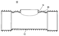
図1に示す枝付管10は本管12の側壁に本管12より小径の支管14が接続し、両端が拡径受口であるリブ付硬質塩化ビニル枝付管であり、これを原管として準備する。この本管12の両端から本管12の拡径受口と同径の金属製の支持管16をそれぞれ挿入して、支管14を拡径する際に本管12が変形したり、割れたりしないように本管12を保護する。
A
次に、この支管14内に図2に示す拡径用金型18を挿入して、支管14の径を拡径する。拡径用金型18は、支管14の内径と同径または小径の円柱形状の小径部20から拡径して、拡径部22から本管12と同径の円柱形状の大径部24へと連結する形状であり、大径部24の高さH1は枝付管10の支管14の高さH2より大きい。
Next, the diameter expansion die 18 shown in FIG. 2 is inserted into the
この拡径用金型18および枝付管10をヒータなどで、たとえば塩化ビニル樹脂の熱変形温度100〜150度程度まで加熱して、拡径用金型18の小径部20を枝付管10の支管14の外側から支管14内に挿入する。そして、支管14内に拡径用金型18の拡径部22を圧入し、支管14の径を拡径用金型18の径に合わせて徐々に拡径させて、支管14内に拡径用金型18の大径部24まで挿入する。
The
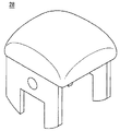
図3に示すように、拡径用金型18の圧入により、本管12の側壁上部における支管14の基部14aの周囲は本管12の内側へ落ち込みたるんでしまい、この部分26の本管12が縮径してしまう。このため、図4に示すようにたるみ整形用治具28を配置して、本管12のたるみ部分26を本管12の内側から外側に向かって押し上げる。このたるみ整形用治具28は、図5に示すように、角柱形状であり、上面は円頂形状、つまり本管12管軸方向に円弧形状で、かつ本管12管軸直交方向にも円弧形状である。
As shown in FIG. 3, due to the press-fitting of the diameter-expanding
本管12を整形すると、本管12の側壁のたるんだ部分26は少し拡径して、本管12の有効断面積は減少せずに維持される。
When the
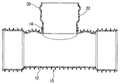
図6に示すように、最後に支管14内から拡径用金具18を、本管12内から支持管16およびたるみ整形用治具28を除き、図7に示すように、支管14内に塩化ビニル用接着剤などを塗布してから、ゴム輪受口30となっている支管接続部32を挿入して組み付ける。
As shown in FIG. 6, the diameter
このように、本管12より小径の支管14を有する市販の枝付管10を利用して、この支管14の外側から支管14内へ拡径用金型18を挿入し支管14を拡径することにより、支管14を本管12と同径にすることができる。この際、拡径用金型18の圧入により本管12はたるんで縮径するが、たるみ整形用治具28を用いてこれを整形するため、本管12と支管14との間に縮径部が形成されず、本管12および支管14のメンテナンスなどの作業を容易に行うことができる。また、この方法には複雑加工や大型製造装置などが必要なく、枝付管10を簡単かつ低コストで製造できる。
In this way, by using the commercially
また、拡径用金型18を挿入して支管14を拡径するため、枝付管10の種類は制限されず、このようなリブ付硬質塩化ビニル樹脂製枝付管10にも適用することができ、もちろんその他のリブがないタイプの枝付管にも適用可能である。
Further, since the
なお、拡径用金型18を用いて支管14を拡径したが、拡・縮径機能を有する金型などを代わりに用いて支管14を拡径してもよい。または、ゴム製チューブなどに圧縮した気体を送り込んで支管14を拡径してもよい。
Although the diameter of the
また、両端が拡径受口の枝付管10を用いたが、枝付管に拡径受口を設けなくてもよい。この枝付管に支持管16を挿入する場合、本管12の管軸方向に支管14の開口縁14aを中心として少なくとも本管12の径Φ1より外側に支持管16を配置して、支管14を拡径する際に支持管16が邪魔にならないようにする。
In addition, although the
10…枝付管
12…本管
14…支管
18…拡径用金型
28…たるみ整形用治具
32…支管接続部
DESCRIPTION OF
Claims (2)
(b)前記支管を加熱拡径し、
(c)前記支管の基部の前記本管の変形部を前記本管の内側から外側へ押し出し、そして
(d)前記支管に支管接続部を取り付ける、枝付管の製造方法。 (A) Prepare a branch pipe whose main pipe diameter is larger than the branch pipe diameter as the original pipe,
(B) expanding the diameter of the branch pipe by heating;
(C) A branch pipe manufacturing method in which a deformed portion of the main pipe at the base of the branch pipe is extruded from the inside to the outside of the main pipe, and (d) a branch pipe connecting portion is attached to the branch pipe.
本管の径が支管の径より大きい枝付管を原管として用いて前記支管を加熱拡径し、前記支管を加熱拡径する際にその支管部に生じる変形部を前記本管の内側から押し出したことを特徴とする、枝付管。
In branch pipes with branch pipe connections attached to branch pipes,
The branch pipe is heated and expanded using a branch pipe having a main pipe diameter larger than that of the branch pipe as an original pipe, and a deformed portion generated in the branch pipe portion when the branch pipe is heated and expanded from the inside of the main pipe. Branched tube characterized by being extruded.
Priority Applications (1)
| Application Number | Priority Date | Filing Date | Title |
|---|---|---|---|
| JP2004121020A JP4471719B2 (en) | 2004-04-16 | 2004-04-16 | Branched tube and manufacturing method thereof |
Applications Claiming Priority (1)
| Application Number | Priority Date | Filing Date | Title |
|---|---|---|---|
| JP2004121020A JP4471719B2 (en) | 2004-04-16 | 2004-04-16 | Branched tube and manufacturing method thereof |
Publications (2)
| Publication Number | Publication Date |
|---|---|
| JP2005299897A true JP2005299897A (en) | 2005-10-27 |
| JP4471719B2 JP4471719B2 (en) | 2010-06-02 |
Family
ID=35331660
Family Applications (1)
| Application Number | Title | Priority Date | Filing Date |
|---|---|---|---|
| JP2004121020A Expired - Lifetime JP4471719B2 (en) | 2004-04-16 | 2004-04-16 | Branched tube and manufacturing method thereof |
Country Status (1)
| Country | Link |
|---|---|
| JP (1) | JP4471719B2 (en) |
Cited By (1)
| Publication number | Priority date | Publication date | Assignee | Title |
|---|---|---|---|---|
| CN101793337A (en) * | 2010-03-10 | 2010-08-04 | 华瀚科技有限公司 | Plastic-steel spirally-wound three-way pipe and manufacturing method thereof |
-
2004
- 2004-04-16 JP JP2004121020A patent/JP4471719B2/en not_active Expired - Lifetime
Cited By (2)
| Publication number | Priority date | Publication date | Assignee | Title |
|---|---|---|---|---|
| CN101793337A (en) * | 2010-03-10 | 2010-08-04 | 华瀚科技有限公司 | Plastic-steel spirally-wound three-way pipe and manufacturing method thereof |
| CN101793337B (en) * | 2010-03-10 | 2012-10-17 | 华瀚科技有限公司 | A plastic-steel winding pipe tee and its manufacturing method |
Also Published As
| Publication number | Publication date |
|---|---|
| JP4471719B2 (en) | 2010-06-02 |
Similar Documents
| Publication | Publication Date | Title |
|---|---|---|
| EP0883476A1 (en) | Process for fabricating cross-linked polyethylene tubing ends | |
| JP2006527092A5 (en) | ||
| JP2669487B2 (en) | Metal tightening connection device | |
| US10677382B2 (en) | Pipe joint device and method for manufacturing the same | |
| KR101506797B1 (en) | Flanging method for pipe | |
| CN110906065A (en) | Outer polygonal reinforced corrugated pipe and forming process thereof | |
| US5597185A (en) | One piece tubular elbow and process of manufacture | |
| AU680126B2 (en) | A method for manufacturing a thermoplastic pipe | |
| JP2005299897A (en) | Pipe with branch and its manufacturing method | |
| CN1270119C (en) | Spigot and socket joint steel pipe and its manufacture | |
| KR101985678B1 (en) | Method of manufacturing a fastening socket for a muffler | |
| KR20200083405A (en) | Pipe joint device and method for manufacturing the same | |
| JP3018147B2 (en) | Large diameter pipe fittings | |
| CN213900285U (en) | Conversion connecting pipe fitting for pipeline | |
| US5601776A (en) | Method and a mould for forming an expansion, such as a socket, in a pipe, and a plastic pipe | |
| JP4278616B2 (en) | Method of manufacturing cover for silencer or catalyst | |
| JPH07217776A (en) | Ribbed bellows tube and method of manufacturing the same | |
| CN215333814U (en) | Socket device for pipe flaring and lining pipe assembly | |
| CN112377709B (en) | Conversion connecting pipe fitting for pipeline | |
| JPH11248065A (en) | Manufacturing method of flanged pipe | |
| JP2005001232A (en) | Branch pipe joint and manufacturing method thereof | |
| JPH08142188A (en) | Mold for molding pipe fittings | |
| EP2886922A1 (en) | Pipe joint incorporating an insert | |
| CN108321328B (en) | A method of manufacturing a battery holder | |
| JP2004322324A (en) | Method for manufacturing rib pipe with branch pipe |
Legal Events
| Date | Code | Title | Description |
|---|---|---|---|
| RD02 | Notification of acceptance of power of attorney |
Free format text: JAPANESE INTERMEDIATE CODE: A7422 Effective date: 20050825 |
|
| A625 | Written request for application examination (by other person) |
Free format text: JAPANESE INTERMEDIATE CODE: A625 Effective date: 20070319 |
|
| A977 | Report on retrieval |
Free format text: JAPANESE INTERMEDIATE CODE: A971007 Effective date: 20091208 |
|
| A131 | Notification of reasons for refusal |
Free format text: JAPANESE INTERMEDIATE CODE: A131 Effective date: 20091215 |
|
| A521 | Request for written amendment filed |
Free format text: JAPANESE INTERMEDIATE CODE: A523 Effective date: 20100212 |
|
| TRDD | Decision of grant or rejection written | ||
| A01 | Written decision to grant a patent or to grant a registration (utility model) |
Free format text: JAPANESE INTERMEDIATE CODE: A01 Effective date: 20100302 |
|
| A01 | Written decision to grant a patent or to grant a registration (utility model) |
Free format text: JAPANESE INTERMEDIATE CODE: A01 |
|
| A61 | First payment of annual fees (during grant procedure) |
Free format text: JAPANESE INTERMEDIATE CODE: A61 Effective date: 20100302 |
|
| FPAY | Renewal fee payment (event date is renewal date of database) |
Free format text: PAYMENT UNTIL: 20130312 Year of fee payment: 3 |
|
| R150 | Certificate of patent or registration of utility model |
Ref document number: 4471719 Country of ref document: JP Free format text: JAPANESE INTERMEDIATE CODE: R150 Free format text: JAPANESE INTERMEDIATE CODE: R150 |
|
| FPAY | Renewal fee payment (event date is renewal date of database) |
Free format text: PAYMENT UNTIL: 20140312 Year of fee payment: 4 |
|
| S533 | Written request for registration of change of name |
Free format text: JAPANESE INTERMEDIATE CODE: R313533 |
|
| R350 | Written notification of registration of transfer |
Free format text: JAPANESE INTERMEDIATE CODE: R350 |
|
| EXPY | Cancellation because of completion of term |