JP2005299989A - Heat exchanger tank - Google Patents
Heat exchanger tank Download PDFInfo
- Publication number
- JP2005299989A JP2005299989A JP2004115099A JP2004115099A JP2005299989A JP 2005299989 A JP2005299989 A JP 2005299989A JP 2004115099 A JP2004115099 A JP 2004115099A JP 2004115099 A JP2004115099 A JP 2004115099A JP 2005299989 A JP2005299989 A JP 2005299989A
- Authority
- JP
- Japan
- Prior art keywords
- tank
- heat exchanger
- fluid
- shape
- bead
- Prior art date
- Legal status (The legal status is an assumption and is not a legal conclusion. Google has not performed a legal analysis and makes no representation as to the accuracy of the status listed.)
- Pending
Links
- 239000011324 bead Substances 0.000 claims abstract description 28
- 239000012530 fluid Substances 0.000 claims abstract description 24
- 230000003014 reinforcing effect Effects 0.000 claims description 21
- 230000002787 reinforcement Effects 0.000 abstract description 6
- 230000000694 effects Effects 0.000 description 1
- 238000004049 embossing Methods 0.000 description 1
- 238000004519 manufacturing process Methods 0.000 description 1
Images

Landscapes
- Heat-Exchange Devices With Radiators And Conduit Assemblies (AREA)
Abstract
Description
本発明は、自動車用ラジエータ、インタークーラ等のコアの端部に設けられる熱交換器用タンクに関する。 The present invention relates to a heat exchanger tank provided at an end of a core of an automobile radiator, an intercooler, or the like.
従来、自動車用ラジエータ等の熱交換器は、チューブ及びフィンから成るコアと、該コアの端部に設けられたヘッダプレートと、該ヘッダプレートに嵌着可能なタンク1とから概略構成されている。
2. Description of the Related Art Conventionally, a heat exchanger such as a radiator for an automobile is generally configured by a core made of tubes and fins, a header plate provided at an end of the core, and a
そして、この熱交換器のタンク1は、図7及び図8に示されているように、前記ヘッダプレート側が開口された細長箱状を成しており、一端部には流体入口3が開口され、その側方には、タンク1の長手方向に対して直角を成す方向に、凹状の補強用ビード2が絞り加工により一体成形されている。(例えば、特許文献1参照)。
As shown in FIGS. 7 and 8, the
しかしながら、上記した従来の熱交換器用タンク1では、補強用ビード2がタンク1の長手方向に対して直角を成す方向に形成されているため、流体入口3からタンク1内に流入し、タンク1内部を流通する流体の流通が補強用ビード2によって妨げられ、その流体の流通抵抗が増大するといった問題があった。
However, in the conventional
また、上記した従来の熱交換器用タンク1では、補強用ビード2をタンク1と一体に成形するようになっているため、複雑な形状の補強用ビード2を成形することができず、補強用ビード2の形状は単純なものに限定されるといった問題があった。
Further, in the conventional
本発明は、上記課題を解決すべくなされたものであり、タンク内部での流体の流れを整流にし、その流体の流通抵抗を低減することができ、また、補強用ビードの形状の自由度を高めることができる熱交換器用タンクを提供しようとするものである。 The present invention has been made to solve the above-mentioned problems, and can rectify the flow of fluid inside the tank, reduce the flow resistance of the fluid, and can increase the flexibility of the shape of the reinforcing bead. It is intended to provide a heat exchanger tank that can be enhanced.
本発明は、チューブ12及びフィン13から成るコア14の端部に設けられる熱交換器11用タンク16であって、補強用ビード20が凹状に形成されており、補強用ビード20は、内部を流通する流体の流通方向に沿って形成されていることを特徴とする。
The present invention is a
そして、好ましくは、補強用ビード20を成形し易いように複数に分割された部材17,18によって構成されている。
And preferably, it is comprised by the
本発明によれば、補強用ビードが内部を流通する流体の流通方向に沿って形成されているため、タンク内部における流体の流れが整流となり、流体の流通抵抗を低減することができる。 According to the present invention, since the reinforcing beads are formed along the flow direction of the fluid flowing through the inside, the flow of the fluid inside the tank is rectified, and the flow resistance of the fluid can be reduced.
また、タンクが複数の部材により構成されている場合には、各種形状の補強用ビードを成形することができるため、タンク内における流体の流通抵抗の低減にとって最適な補強用ビードの形状を自由に選択することができ、補強ビードの形状の自由度を高めることできる等、種々の優れた効果を得ることができる。 In addition, when the tank is composed of a plurality of members, reinforcing beads having various shapes can be formed. Therefore, the shape of the reinforcing beads optimal for reducing the flow resistance of the fluid in the tank can be freely set. Various excellent effects can be obtained, such as being able to select and increasing the degree of freedom of the shape of the reinforcing bead.
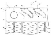
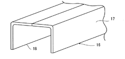
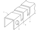
以下、図面を参照しつつ、本発明の実施の形態について説明する。なお、以下の説明では、本発明に係る熱交換器用タンクを自動車用ラジエータに適用した場合について説明する。ここで、図1は本発明の実施の形態に係る熱交換器用タンクを示す正面図、図2はその熱交換器用タンクを示す斜視図である。 Hereinafter, embodiments of the present invention will be described with reference to the drawings. In the following description, a case where the heat exchanger tank according to the present invention is applied to an automobile radiator will be described. Here, FIG. 1 is a front view showing a heat exchanger tank according to an embodiment of the present invention, and FIG. 2 is a perspective view showing the heat exchanger tank.
本実施の形態において、熱交換器11は、チューブ12及びフィン13から成るコア14と、コア14の両端部に設けられたヘッダプレート15と、ヘッダプレート15に嵌着可能なタンク16とから概略構成されている。
In the present embodiment, the
タンク16は、一方の面(図示では、下面)側が開口された細長箱状を成しており、その開口面はヘッダプレート15により閉塞されるようになっている。また、タンク16は、図2に良く示されているように、段状に折曲された前側部材17と、鉛直板状の後側部材18の2部材から構成されており、前側部材17と後側部材18は上端部同士を介して接合されている。前側部材17には、一端部(図示では、正面左側)にタンク16内への流体入口19が開口されており、その流体入口19の側方には複数の補強用ビード20がタンク16内部を流通する流体の流通方向に沿って凹状に形成されている。
The
この場合、タンク16は2部材で構成されているため、補強用ビード20を成形するためにタンク16の上面と両側面の3方向から複雑なエンボス加工等を行う必要がない。したがって、例えば、補強用ビード20を翼形状等、複雑な形状に加工する場合であっても、単純な型を使用して加工することができるため、製造の手間を軽減することができる。
In this case, since the
そして、上記した実施の形態に係る熱交換器用タンク16によれば、流体入口19からタンク16内に流入した流体の流れは、補強用ビード20により整流にされるため、流体の流通抵抗を低減することができる。
According to the
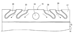
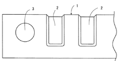
なお、図3に示すように、流体入口19をタンク16の中央に配置し、その流体入口19の両側に補強用ビード20を流体の流通方向に沿って形成させてもよい。
In addition, as shown in FIG. 3, the
また、上記した実施の形態では、タンク16の前側部材17にのみ補強用ビード20が形成されているが、後側部材18にも補強用ビード20を形成させてもよい。
In the above-described embodiment, the reinforcing
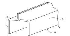
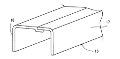
さらに、タンク16の前側部材17と後側部材18の形状は、上記した形状に限定されるものではなく、例えば、図4に示すように、後側部材18も前側部材17と同様に段状に折曲させたり、又は、図5に示すように、前側部材17及び後側部材18を共にL字型に折曲し、両者の端部同士を重合させて接合させたり、或いは、図6に示すように、前側部材17及び後側部材18を共にL字型に折曲し、両者を突合せ接合させたりしてもよい。さらにまた、タンク16は、3部材以上に複数分割してもよく、或いは、その分割を長手方向に沿って前側部材17と後側部材に2分割するのではなく、長手方向に対して直角の方向に複数に分割する等、各種変更が可能である。
Further, the shapes of the
さらに、本発明は、上記した自動車用ラジエータに限らず、自動車用インタークーラや産業用アフタークーラ等、他の熱交換器にも適用可能であることは言う迄もない。 Furthermore, it goes without saying that the present invention is applicable not only to the above-described automobile radiator but also to other heat exchangers such as an automobile intercooler and an industrial aftercooler.
11 熱交換器
12 チューブ
13 フィン
14 コア
16 タンク
17 前側部材
18 後側部材
20 補強用ビード
DESCRIPTION OF
Claims (2)
補強用ビードが凹状に形成されており、該補強用ビードは、内部を流通する流体の流通方向に沿って形成されていることを特徴とする熱交換器用タンク。 A heat exchanger tank provided at an end of a core composed of tubes and fins,
A heat exchanger tank, wherein a reinforcing bead is formed in a concave shape, and the reinforcing bead is formed along a flow direction of a fluid flowing through the inside.
Priority Applications (1)
| Application Number | Priority Date | Filing Date | Title |
|---|---|---|---|
| JP2004115099A JP2005299989A (en) | 2004-04-09 | 2004-04-09 | Heat exchanger tank |
Applications Claiming Priority (1)
| Application Number | Priority Date | Filing Date | Title |
|---|---|---|---|
| JP2004115099A JP2005299989A (en) | 2004-04-09 | 2004-04-09 | Heat exchanger tank |
Publications (1)
| Publication Number | Publication Date |
|---|---|
| JP2005299989A true JP2005299989A (en) | 2005-10-27 |
Family
ID=35331736
Family Applications (1)
| Application Number | Title | Priority Date | Filing Date |
|---|---|---|---|
| JP2004115099A Pending JP2005299989A (en) | 2004-04-09 | 2004-04-09 | Heat exchanger tank |
Country Status (1)
| Country | Link |
|---|---|
| JP (1) | JP2005299989A (en) |
Cited By (2)
| Publication number | Priority date | Publication date | Assignee | Title |
|---|---|---|---|---|
| WO2008023569A1 (en) | 2006-08-22 | 2008-02-28 | Calsonic Kansei Corporation | Tank structure of heat exchanger |
| WO2017208558A1 (en) * | 2016-06-02 | 2017-12-07 | 株式会社日立製作所 | Heat exchanger |
-
2004
- 2004-04-09 JP JP2004115099A patent/JP2005299989A/en active Pending
Cited By (3)
| Publication number | Priority date | Publication date | Assignee | Title |
|---|---|---|---|---|
| WO2008023569A1 (en) | 2006-08-22 | 2008-02-28 | Calsonic Kansei Corporation | Tank structure of heat exchanger |
| WO2017208558A1 (en) * | 2016-06-02 | 2017-12-07 | 株式会社日立製作所 | Heat exchanger |
| JPWO2017208558A1 (en) * | 2016-06-02 | 2019-02-21 | 株式会社日立製作所 | Heat exchanger |
Similar Documents
| Publication | Publication Date | Title |
|---|---|---|
| CN100559107C (en) | Heat exchanger and internal combustion engine with the same | |
| JP5821795B2 (en) | Heat exchanger | |
| JP6547576B2 (en) | Heat exchanger | |
| JP5803768B2 (en) | Heat exchanger fins and heat exchangers | |
| JP2012026407A (en) | Intercooler | |
| KR20170063543A (en) | Corrugated fins for heat exchanger | |
| JP2005221127A (en) | Core part structure of heat exchanger | |
| JP2007333254A (en) | Tube for heat-exchanger | |
| JP2007218455A (en) | Heat exchanger | |
| JP2007163040A (en) | Header tank for heat exchanger and method of manufacturing outer plate for use therein | |
| JPH1162587A (en) | Radiator with built-in oil cooler | |
| JP2007178015A (en) | Heat exchanger | |
| JP2005299989A (en) | Heat exchanger tank | |
| JP6051641B2 (en) | Intercooler for vehicle | |
| WO2017030089A1 (en) | Heat exchanger | |
| JP5030677B2 (en) | Heat exchanger tank structure | |
| JPWO2019163973A1 (en) | Heat exchanger tank structure | |
| JP4239840B2 (en) | Mouth expansion jig for heat exchanger tubes | |
| JP2007093024A (en) | Heat exchanger | |
| JP2005083700A (en) | Heat exchange tube | |
| KR102406998B1 (en) | Intercooler | |
| JP2008008603A (en) | Heat exchanger | |
| JP2005114199A (en) | Header for heat exchanger and manufacturing method thereof | |
| JP2017227342A (en) | Corrugated fin type heat exchanger | |
| JP4613832B2 (en) | Heat exchanger |
Legal Events
| Date | Code | Title | Description |
|---|---|---|---|
| A621 | Written request for application examination |
Effective date: 20061113 Free format text: JAPANESE INTERMEDIATE CODE: A621 |
|
| A977 | Report on retrieval |
Free format text: JAPANESE INTERMEDIATE CODE: A971007 Effective date: 20090624 |
|
| A131 | Notification of reasons for refusal |
Effective date: 20090710 Free format text: JAPANESE INTERMEDIATE CODE: A131 |
|
| A521 | Written amendment |
Free format text: JAPANESE INTERMEDIATE CODE: A523 Effective date: 20090826 |
|
| A02 | Decision of refusal |
Effective date: 20091005 Free format text: JAPANESE INTERMEDIATE CODE: A02 |