JP2005347310A - Electronic component mounting equipment - Google Patents
Electronic component mounting equipment Download PDFInfo
- Publication number
- JP2005347310A JP2005347310A JP2004161731A JP2004161731A JP2005347310A JP 2005347310 A JP2005347310 A JP 2005347310A JP 2004161731 A JP2004161731 A JP 2004161731A JP 2004161731 A JP2004161731 A JP 2004161731A JP 2005347310 A JP2005347310 A JP 2005347310A
- Authority
- JP
- Japan
- Prior art keywords
- stator
- tension
- axis
- linear motor
- stress
- Prior art date
- Legal status (The legal status is an assumption and is not a legal conclusion. Google has not performed a legal analysis and makes no representation as to the accuracy of the status listed.)
- Granted
Links
Images


Landscapes
- Supply And Installment Of Electrical Components (AREA)
- Linear Motors (AREA)
Abstract
【課題】 移載ヘッドの移動にシャフトモータ式のリニアモータを用いた場合に、固定子の振動及び変形を抑制する。電子部品実装装置の提供。
【解決手段】 電子部品を移載する移載ヘッド12と、移載ヘッド12を保持してX軸方向へ移動させるX軸リニアモータ7と、X軸リニアモータ7を支持しX軸方向へ延びるX軸ビーム部材6と、X軸ビーム部材6ごと移載ヘッド12をX軸リニアモータ7の移動方向と垂直なY軸方向へ移動させるY軸リニアモータ3と、を備えた電子部品実装装置1において、X軸リニアモータ7は、X軸方向へ延びX軸ビーム部材6に両端が支持されるシャフト状の固定子7aと、移載ヘッド12に設けられ固定子7aを包囲し固定子7aに沿って移動する可動子7bと、を有し、固定子7aに張力を付与する張力付与手段を具備した。
【選択図】図2PROBLEM TO BE SOLVED: To suppress vibration and deformation of a stator when a shaft motor type linear motor is used for movement of a transfer head. Provide electronic component mounting equipment.
A transfer head 12 for transferring an electronic component, an X-axis linear motor 7 that holds the transfer head 12 and moves it in the X-axis direction, supports the X-axis linear motor 7, and extends in the X-axis direction. Electronic component mounting apparatus 1 comprising an X-axis beam member 6 and a Y-axis linear motor 3 that moves the transfer head 12 together with the X-axis beam member 6 in the Y-axis direction perpendicular to the movement direction of the X-axis linear motor 7. The X-axis linear motor 7 includes a shaft-like stator 7a extending in the X-axis direction and supported at both ends by the X-axis beam member 6, and surrounding the stator 7a provided on the transfer head 12, and And a tension applying means for applying tension to the stator 7a.
[Selection] Figure 2
Description
本発明は、供給された電子部品を、移載ヘッドを用いて電子基板の所定位置へ搬送して実装する電子部品実装装置に関する。 The present invention relates to an electronic component mounting apparatus for transporting and mounting a supplied electronic component to a predetermined position on an electronic substrate using a transfer head.
電子部品実装装置において、電子部品を搬送する移載ヘッドは、X軸の移動に関するモータと、Y軸の移動に関するモータとにより、水平方向へ移動する。近年、移載ヘッドの移動にリニアモータを用い、移載ヘッドの整定精度を向上させたものが知られている。この場合、リニアモータの可動子は移載ヘッドに設けられ、固定子は移動方向へ延びるビーム部材に支持されることとなる。電子部品実装装置に用いられるリニアモータとしては、可動子にヨークが配されないコアレスタイプのものと(例えば、特許文献1参照)、可動子にヨークが配されるコア付きタイプのものと(例えば、特許文献2参照)、が公知である。 In the electronic component mounting apparatus, a transfer head that transports an electronic component moves in the horizontal direction by a motor related to movement of the X axis and a motor related to movement of the Y axis. In recent years, a linear motor is used for moving the transfer head and the setting accuracy of the transfer head is improved. In this case, the mover of the linear motor is provided in the transfer head, and the stator is supported by the beam member extending in the moving direction. As a linear motor used in an electronic component mounting apparatus, a coreless type in which a yoke is not arranged on the mover (for example, refer to Patent Document 1), and a type with a core in which a yoke is arranged on the mover (for example, Patent Document 2) is known.
コアレスタイプのリニアモータを用いた場合、可動子と固定子の吸引力が生じないためこれらの組付が容易であるし、可動子を保持して軸方向へ案内するリニアガイドに加わる負荷が比較的小さいことからリニアガイドに大きな剛性が要求されないという利点がある。しかし、可動子にヨークが存在しないので駆動の効率が悪く、可動子のコイルに比較的大きな電流を流すこととなり、可動子の発熱量が大きくなる。従って、可動子に生じる熱により、装置の各構成部品等が変形して、移載ヘッドの整定精度が低下するという問題点がある。 When a coreless type linear motor is used, there is no suction force between the mover and stator, making it easy to assemble them, and the load applied to the linear guide that holds the mover and guides it in the axial direction is compared. Therefore, there is an advantage that a large rigidity is not required for the linear guide. However, since the yoke does not exist in the mover, the driving efficiency is poor, and a relatively large current flows through the coil of the mover, and the amount of heat generated by the mover increases. Therefore, there is a problem that the component parts of the apparatus are deformed by the heat generated in the mover and the setting accuracy of the transfer head is lowered.
一方、コア付きタイプのリニアモータを用いた場合は、可動子にヨークが存在するので駆動の効率が良く、可動子の発熱量を抑制して装置の各構成部品等の熱変形を抑止することができる。しかし、固定子との吸引力が可動子に作用するとともに、可動子にヨークを配するために可動子の重量が増加するので、リニアガイドに大きな剛性が要求され、リニアガイドを強固に構成する必要が生じる。
上記各問題点を解決するため、シャフトモータ式のリニアモータを採用することが考えられる。シャフトモータ式では、シャフト状の固定子を可動子により包囲するので、コアレスタイプの利点を活かしつつ、固定子により生じた磁界を無駄なく利用して可動子の発熱量を抑制することができる。 In order to solve the above problems, it is conceivable to employ a shaft motor type linear motor. In the shaft motor type, since the shaft-shaped stator is surrounded by the mover, it is possible to suppress the heat generation amount of the mover by using the magnetic field generated by the stator without waste while taking advantage of the coreless type.
しかしながら、可動子がシャフト状の固定子を包囲し固定子に沿って移動するため、可動子の移動範囲内で固定子を支持することができない。従って、長尺な固定子をその両端でビーム部材により支持することとなり、固定子の曲げ剛性が低くなるという問題点が生じる。すなわち、可動子により移載ヘッドをX軸方向へ移動させ、ビーム部材ごと移載ヘッドをY軸方向へ移動させるもののように、ビーム部材に垂直な方向へ加速度が加わると、固定子が振動しつつ変形して可動子と干渉するおそれがある。また、固定子が振動することから、移載ヘッドの移動制御における追従性が悪化することは勿論、移載ヘッドの整定時間が長くなるとともに、整定精度が悪化するという問題点も生じる。 However, since the mover surrounds the shaft-like stator and moves along the stator, the stator cannot be supported within the moving range of the mover. Therefore, the long stator is supported by the beam members at both ends thereof, which causes a problem that the bending rigidity of the stator is lowered. That is, the stator vibrates when acceleration is applied in a direction perpendicular to the beam member, such as moving the transfer head in the X-axis direction by the mover and moving the transfer head together with the beam member in the Y-axis direction. However, there is a risk of deformation and interference with the mover. Further, since the stator vibrates, not only the followability in the movement control of the transfer head is deteriorated, but also the settling time of the transfer head becomes longer and the settling accuracy is deteriorated.
本発明は、前記事情に鑑みてなされたものであり、その目的とするところは、移載ヘッドの移動にシャフトモータ式のリニアモータを用いた場合に、固定子の振動及び変形を抑制することのできる電子部品実装装置を提供することにある。 The present invention has been made in view of the above circumstances, and its object is to suppress vibration and deformation of the stator when a shaft motor type linear motor is used for movement of the transfer head. It is an object to provide an electronic component mounting apparatus capable of performing the above.
前記目的を達成するため、請求項1に記載の発明では、電子部品を移載する移載ヘッドと、前記移載ヘッドを保持して所定の軸方向へ移動させるリニアモータと、前記リニアモータを支持し前記軸方向へ延びるビーム部材と、前記ビーム部材ごと前記移載ヘッドを前記リニアモータの移動方向と垂直な軸方向へ移動させるビーム移動装置と、を備えた電子部品実装装置において、前記リニアモータは、前記軸方向へ延び前記ビーム部材に両端が支持されるシャフト状の固定子と、前記移載ヘッドに設けられ、前記固定子を包囲し前記固定子に沿って移動する可動子と、を有し、前記固定子に張力を付与する張力付与手段を具備したことを特徴とする。 In order to achieve the above object, according to the first aspect of the present invention, there is provided a transfer head for transferring an electronic component, a linear motor for holding the transfer head and moving it in a predetermined axial direction, and the linear motor. An electronic component mounting apparatus comprising: a beam member that supports and extends in the axial direction; and a beam moving device that moves the transfer head together with the beam member in an axial direction perpendicular to a moving direction of the linear motor. The motor extends in the axial direction and has a shaft-like stator that is supported at both ends by the beam member, a movable element that is provided in the transfer head, surrounds the stator and moves along the stator, And a tension applying means for applying tension to the stator.
請求項1に記載の発明によれば、供給される電子部品の電子基板への搬送に際し、移載ヘッドは、所定の軸方向へリニアモータにより移動されるとともに、この移動方向と垂直な軸方向にビーム移動装置によりビーム部材ごと移動される。
ここで、固定子には張力付与手段により張力が付与され、固定子の固有振動数が増大している。すなわち、シャフト状の固定子は固有振動数が高いので振動時の変形量が小さくなっており、この結果、動的な剛性が向上している。これにより、ビーム移動装置の駆動時には、長尺な固定子に軸方向と垂直な方向の加速度が作用することとなるが、固定子の動的な剛性が向上していることから振動を抑制することができるし、振動しても変形量が小さなものとなる。
According to the first aspect of the present invention, the transfer head is moved in the predetermined axial direction by the linear motor and the axial direction perpendicular to the moving direction when transporting the supplied electronic component to the electronic substrate. The beam member is moved by the beam moving device.
Here, tension is applied to the stator by the tension applying means, and the natural frequency of the stator is increased. That is, since the shaft-shaped stator has a high natural frequency, the amount of deformation during vibration is small, and as a result, dynamic rigidity is improved. As a result, when the beam moving device is driven, acceleration in a direction perpendicular to the axial direction acts on the long stator, but vibration is suppressed because the dynamic rigidity of the stator is improved. Even if it vibrates, the amount of deformation is small.
請求項2に記載の発明では、請求項1に記載の電子部品実装装置において、前記張力付与手段は、前記ビーム移動装置の駆動により前記ビーム部材に加速度が作用するときに、前記固定子に張力を付与することを特徴とする。 According to a second aspect of the present invention, in the electronic component mounting apparatus according to the first aspect, the tension applying unit is configured to apply tension to the stator when acceleration is applied to the beam member by driving the beam moving device. It is characterized by giving.
請求項2に記載の発明によれば、請求項1の作用に加え、ビーム部材に加速度が生じて固定子が曲げ方向に変形するときに固定子に張力が付与されるので、曲げ方向の負荷が加わらないときにまで固定子に張力が付与されることはない。 According to the second aspect of the present invention, in addition to the action of the first aspect, when the acceleration is generated in the beam member and the stator is deformed in the bending direction, tension is applied to the stator. No tension is applied to the stator until no additional force is applied.
請求項3に記載の発明では、請求項1または2に記載の電子部品実装装置において、前記張力付与手段は、前記ビーム移動装置の駆動により前記ビーム部材に生じる加速度に応じて、前記固定子の張力を変動させることを特徴とする。 According to a third aspect of the present invention, in the electronic component mounting apparatus according to the first or second aspect, the tension applying unit may be configured so that the stator member is in accordance with an acceleration generated in the beam member by driving the beam moving device. It is characterized by varying the tension.
請求項3に記載の発明によれば、請求項1または2の作用に加え、ビーム部材に生じる加速度に応じて固定子に張力が付与されるので、固定子に要求される剛性に対応したきめ細やかな張力付与制御が実現される。 According to the third aspect of the invention, in addition to the action of the first or second aspect, tension is applied to the stator in accordance with the acceleration generated in the beam member, so that the texture corresponding to the rigidity required for the stator is obtained. Fine tensioning control is realized.
請求項4に記載の発明では、請求項1から3のいずれか一項に記載の電子部品実装装置において、前記固定子の応力を検出する応力検出手段を備え、前記張力付与手段は、前記応力検出手段により検出された応力に対応して、前記固定子に張力を付与することを特徴とする。 According to a fourth aspect of the present invention, in the electronic component mounting apparatus according to any one of the first to third aspects, the electronic component mounting apparatus includes a stress detection unit that detects a stress of the stator, and the tension applying unit includes the stress applying unit. A tension is applied to the stator in accordance with the stress detected by the detecting means.
請求項4に記載の発明によれば、請求項1から3のいずれか一項の作用に加え、応力検出手段により検出された固定子の応力に対応して張力を付与するので、固定子に要求される剛性に対応したきめ細やかな張力付与制御が実現される。また、固定子の応力を直接検出することから、例えば、吸着ノズルの交換により移載ヘッドの重量が変化したり、電子部品の積載状態と非積載状態とで移載ヘッドの重量が変化したり、搬送する電子部品の種類により移載ヘッドの重量が変化して、固定子に加わる応力が変化する場合にも、これに対応して的確に固定子に張力を付与することができる。
また、例えば経年劣化により固定子に付与される張力が所期の値から変化した場合にも、固定子に加わる応力が変化する。従って、経年劣化により応力変化に対応して、的確に固定子に張力を付与することもできる。
According to the invention described in
Further, for example, when the tension applied to the stator is changed from an expected value due to aging deterioration, the stress applied to the stator is changed. Therefore, it is possible to accurately apply tension to the stator in response to stress changes due to aging.
請求項5に記載の発明では、請求項1から3のいずれか一項に記載の電子部品実装装置において、前記固定子の応力を検出する応力検出手段と、前記応力検出手段により検出された応力に基づく情報を表示する応力情報表示手段と、を備えたことを特徴とする。 According to a fifth aspect of the present invention, in the electronic component mounting apparatus according to any one of the first to third aspects, the stress detection means for detecting the stress of the stator, and the stress detected by the stress detection means Stress information display means for displaying information based on the above.
請求項5に記載の発明によれば、請求項1から3のいずれか一項の作用に加え、応力検出手段により検出された固定子の応力に基づく情報を応力情報表示手段により表示するようにしたので、作業者は応力に基づく情報を確認することができる。これにより、例えば、吸着ノズルの交換により移載ヘッドの重量が変化したり、電子部品の積載状態と非積載状態とで移載ヘッドの重量が変化したり、搬送する電子部品の種類により移載ヘッドの重量が変化して、固定子に加わる応力が変化する場合にも、作業者はこれに対応して固定子に付与される張力を調整することができる。
また、例えば、経年劣化により固定子に付与される張力が所期の値から変化した場合や、張力付与手段が正常に動作しない場合にも、固定子に加わる応力が変化する。従って、作業者は、経年劣化に対応して固定子に付与される張力を付与したり、装置の故障等を認識したりすることができる。
According to the fifth aspect of the invention, in addition to the action of any one of the first to third aspects, information based on the stress of the stator detected by the stress detection means is displayed by the stress information display means. Therefore, the operator can confirm the information based on the stress. As a result, for example, the weight of the transfer head changes due to the replacement of the suction nozzle, the weight of the transfer head changes depending on whether the electronic component is loaded or not, and the transfer depends on the type of electronic component to be transferred Even when the weight of the head changes and the stress applied to the stator changes, the operator can adjust the tension applied to the stator correspondingly.
In addition, for example, when the tension applied to the stator is changed from an expected value due to aging, or when the tension applying means does not operate normally, the stress applied to the stator changes. Therefore, the operator can apply a tension applied to the stator corresponding to the aging deterioration, and can recognize a failure of the apparatus.
請求項6に記載の発明では、請求項1から5のいずれか一項に記載の電子部品実装装置において、前記ビーム部材における前記固定子と軸中心反対側に両端が支持される補正ロッドと、前記張力付与手段により前記固定子に付与される張力に応じて、前記補正ロッドに張力を付与する張力補正手段を備えたことを特徴とする。 According to a sixth aspect of the present invention, in the electronic component mounting apparatus according to any one of the first to fifth aspects, a correction rod whose both ends are supported on the opposite side of the axial center of the beam member, Tension correction means for applying tension to the correction rod according to the tension applied to the stator by the tension application means is provided.
請求項6に記載の発明によれば、請求項1から5のいずれか一項の作用に加え、張力付与手段により固定子に張力が付与されると、張力補正手段により補正ロッドに張力が付与される。このとき、ビーム部材には、固定子から加わる曲げ方向の力と、補正ロッドから加わる曲げ方向の力とが加わることとなる。ここで、補正ロッドは固定子と軸中心について反対側に配されていることから、ビーム部材において固定子からの曲げ方向の力と、補正ロッドから加わる曲げ方向の力とが相殺される。
According to the invention described in
請求項1に記載の発明によれば、移載ヘッドの移動にシャフトモータ式のリニアモータを用いた場合に、長尺な固定子に軸方向と垂直な方向の加速度が作用しても、固定子の振動及び変形を抑制することができる。また、シャフトモータ式のリニアモータを用いたので、可動子を案内するリニアガイドを簡素な構成とすることができ、固定子により生じた磁界を無駄なく利用して可動子の発熱量を抑制することができる。
これにより、リニアモータ自体の整定性が向上するし、リニアモータの固定子と可動子が干渉しないビーム移動装置の駆動によるビーム部材の加速度の上限が高くなり、ひいてはビーム移動装置の整定性も向上する。従って、電子部品を搬送する際の移載ヘッドの移動時間が短縮され、且つ、移動後の整定時間も短縮されるとともに、移載ヘッドの停止精度が向上する。すなわち、電子基板に対する電子部品の搭載タクト及び搭載精度を向上させることができる。
According to the first aspect of the present invention, when a shaft motor type linear motor is used for the movement of the transfer head, even if acceleration in a direction perpendicular to the axial direction acts on the long stator, it is fixed. The vibration and deformation of the child can be suppressed. Further, since a linear motor of the shaft motor type is used, the linear guide for guiding the mover can be made simple, and the amount of heat generated by the mover is suppressed by using the magnetic field generated by the stator without waste. be able to.
As a result, the settling of the linear motor itself is improved, and the upper limit of the acceleration of the beam member by driving the beam moving device in which the stator and the mover of the linear motor do not interfere with each other increases, thereby improving the settling of the beam moving device. To do. Accordingly, the movement time of the transfer head when the electronic component is conveyed is shortened, the settling time after the movement is shortened, and the stop accuracy of the transfer head is improved. That is, it is possible to improve the mounting tact and mounting accuracy of electronic components on the electronic substrate.
請求項2に記載の発明によれば、請求項1の効果に加え、曲げ方向の負荷が加わらないときにまで固定子に張力が付与されることはなく、固定子に加わる負荷を最小限に抑えることができ、固定子における永久歪みの発生を抑制することができる。 According to the second aspect of the present invention, in addition to the effect of the first aspect, no tension is applied to the stator until the load in the bending direction is not applied, and the load applied to the stator is minimized. It is possible to suppress the occurrence of permanent distortion in the stator.
請求項3に記載の発明によれば、請求項1または2の効果に加え、固定子に要求される剛性に対応したきめ細やかな張力付与制御が実現され、固定子を安定的に制御することができる。 According to the third aspect of the invention, in addition to the effect of the first or second aspect, fine tension applying control corresponding to the rigidity required for the stator is realized, and the stator can be stably controlled. Can do.
請求項4に記載の発明によれば、請求項1から3のいずれか一項の効果に加え、固定子に要求される剛性に対応したきめ細やかな張力付与制御が実現され、固定子を安定的に制御することができる。また、固定子の応力を直接検出することから、固定子に加わる応力が変化する場合にも、これに対応して的確に固定子に張力を付与することができる。
また、曲げ方向の負荷が加わらないときにまで固定子に張力が付与されることはなく、固定子に加わる負荷を最小限に抑えることができ、固定子における永久歪みの発生を抑制することができる。
According to the invention described in
In addition, no tension is applied to the stator until no load in the bending direction is applied, the load applied to the stator can be minimized, and the occurrence of permanent distortion in the stator can be suppressed. it can.
請求項5に記載の発明によれば、請求項1から3のいずれか一項の効果に加え、
作業者は、固定子の応力に基づく情報を把握し、固定子に加わる応力が変化する場合にも、これに対応して固定子に付与される張力を調整することができる。
According to invention of
The operator can grasp information based on the stress of the stator and adjust the tension applied to the stator corresponding to the change in the stress applied to the stator.
請求項6に記載の発明によれば、ビーム部材において固定子からの曲げ方向の力と、補正ロッドから加わる曲げ方向の力とが相殺されるので、ビーム部材の内部応力を低減して曲げ変形を抑制し、ビーム部材の形状精度を維持し、剛性、強度、信頼耐久性を向上することができる。 According to the sixth aspect of the present invention, the bending force from the stator and the bending force applied from the correction rod cancel each other in the beam member. Can be suppressed, the shape accuracy of the beam member can be maintained, and the rigidity, strength, and reliability durability can be improved.
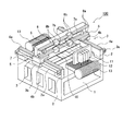
図1から図5は本発明の第1の実施形態を示すもので、図1は電子部品実装装置の外観斜視図、図2は移載ヘッドの一部の分解した状態の電子部品実装装置の一部分解斜視図、図3はX軸リニアモータの概略図、図4はX軸ビーム部材及びX軸リニアモータの縦断面図、図5はX軸ビーム部材及びX軸リニアモータの横断面図である。尚、図1及び図2においては、X軸リニアモータ、Y軸リニアモータ等を模式的に図示している。 1 to 5 show a first embodiment of the present invention, FIG. 1 is an external perspective view of an electronic component mounting apparatus, and FIG. 2 is an exploded view of an electronic component mounting apparatus in which a part of a transfer head is disassembled. 3 is an exploded perspective view, FIG. 3 is a schematic view of an X-axis linear motor, FIG. 4 is a longitudinal sectional view of an X-axis beam member and an X-axis linear motor, and FIG. 5 is a transverse sectional view of the X-axis beam member and the X-axis linear motor. is there. 1 and 2 schematically show an X-axis linear motor, a Y-axis linear motor, and the like.
図1に示すように、この電子部品実装装置100は、略直方体形状を呈する基台1の上側に、移載ヘッド12をX軸へ移動させるX軸リニアモータ7、移載ヘッド12をY軸へ移動させるY軸リニアモータ3等が載置されている。電子部品実装装置100は、パーツフィーダ13から供給される電子部品を、移載ヘッド12に載せてX軸方向へ延びる搬送路9にて位置決めされる電子基板10まで搬送して実装する。
As shown in FIG. 1, the electronic
図1に示すように、基台1の上面のX軸方向両端には、基台1の周縁に沿ってY軸方向へ延びるY軸固定テーブル2がそれぞれ設けられる。各Y軸固定テーブル2の外側面には、Y軸リニアモータ3の固定子3aが設けられる。また、各Y軸固定テーブル2の上面には、Y軸リニアガイド4のレール4aが固定される。
As shown in FIG. 1, Y-axis fixed tables 2 extending in the Y-axis direction along the periphery of the
図1に示すように、各Y軸リニアモータ3は、固定子3aと所定の空隙をおいて配される可動子3bを有する。本実施形態においては、各固定子3aはY軸固定テーブル2に両端が支持されるシャフトであり、各可動子3bは内部にコイルを有し固定子3aを包囲する略直方体状を呈する。これにより、可動子3bが固定子3aに沿ってY軸方向へ移動自在となっている。
As shown in FIG. 1, each Y-axis
この可動子3bは、Y軸移動テーブル5の下面と係合する。また、各Y軸移動テーブル5の下面には、Y軸リニアガイド4のスライダ4bが可動子3bと隣接して係合されている。ここで、スライダ4bはレール4aによりY軸方向へ案内される。これにより、各Y軸移動テーブル5は、Y軸リニアガイド4のレール4bに沿ってY軸方向へ移動自在であり、Y軸リニアモータ3により駆動される。
The
図2に示すように、各Y軸移動テーブル5には、X軸ビーム部材6が架設される。このX軸ビーム部材6は、基台1を跨いでX軸方向へ延び、Y軸の一方に対して凹状の断面略コ字状を呈する。すなわち、本実施形態においては、Y軸リニアモータ3が、X軸ビーム部材6ごと移載ヘッド12をX軸リニアモータ7の移動方向と垂直な軸方向へ移動させるビーム移動手段をなす。このX軸ビーム部材6の凹部分に、X軸リニアモータ7の固定子7aが設けられる。また、X軸ビーム部材6の上下の突出部分には、X軸リニアガイド8のレール8aがそれぞれ固定される。
As shown in FIG. 2, an
図2に示すように、X軸リニアモータ7は、固定子7aと所定の空隙をおいて配される可動子7bを有する。本実施形態においては、固定子7aはX軸ビーム部材6に両端が支持されるシャフトであり、可動子7bは内部にコイルを有し固定子7aを包囲する略直方体状を呈する。これにより、可動子7bが固定子7aに沿ってX軸方向へ移動自在となっている。
As shown in FIG. 2, the X-axis
この可動子7bは、X軸移動テーブル11の前面と係合する。また、X軸移動テーブル11の前面には、各X軸リニアガイド8のスライダ8bが可動子8bと隣接して係合されている。ここで、各スライダ8bはレール8aによりX軸方向へ案内される。これにより、X軸移動テーブル11は、X軸リニアガイド8のレール8bに沿ってX軸方向へ移動自在であり、X軸リニアモータ7により駆動される。
The
ここで、X軸リニアモータ7の可動子7bと、X軸リニアモータ7の固定子7aについて詳述する。
図3に示されるように、固定子7aは、永久磁石15・・・の同極同士が対向するように複数配置され、その周囲を非磁性体であるヨークで覆ったシャフトである。
また、可動子7bは、全体としてシャフト状の固定子7aの周囲を3相のコイルCが周回するように配置されているスライダである。
つまり、このX軸リニアモータ7は、シャフトモータと称される駆動モータである。
Here, the
As shown in FIG. 3, the
The
That is, the X-axis
固定子7aは、長さ(高さ)が60mmから120mm程度であり、一方の端面がN極、他方の端面がS極となる円筒形の永久磁石15を複数有し、その磁石の端面がN極同士、S極同士が向かい合うように重ねて配置されている。各永久磁石15は反発しあるが無理に押し付けるようにして1本の棒状にする。この棒をヨークで覆いシャフトとして形成することにより、リニアモータの固定子7aが形成される。このシャフトにおいて、N極とN極が対向する部分から磁力線が出て、S極とS極が対向する部分に向かう。
The
そのシャフトである固定子7aの外周面を取り囲むように、スライダである可動子7bを配置する。この可動子7bには別途にX軸リニアガイド8を備えるようにし、固定子7aと可動子7bが接触しないように配置されている。
可動子7bには、コイルを固定子7aに巻き付ける方向に3相のコイルCが、シャフトの軸方向に1組から4組程度並べられている。各コイルの長さ(シャフトの軸方向の長さ)はシャフトの磁石のピッチと同じ、つまり60mmから120mmとする。そして、一つのコイルはN極、S極のどちらかから発生する磁束を横切ることになる。これに電流を流すと同期モータとして動作するシャフトモータとなる。このX軸リニアモータ7が動作することにより、可動子7bが固定子7aに沿ってX軸方向に摺動するように移動し、この結果、移載ヘッド12がX軸方向へ移動する。
A
On the
このように、本発明に係る電子部品実装装置1のX軸リニアモータ7は、磁石の同極同士が対向するように複数配置し、その周囲を非磁性体であるヨークで覆ったシャフトを固定子とし、シャフトの周囲を3相のコイルCが周回するように配置されたスライダを可動子7bとするシャフトモータであるので、X軸リニアモータ7の構成を簡素化することができ、組み付け性を向上させることができる。また、電子部品実装装置1におけるスムーズな動作を可能にすることができる。
As described above, a plurality of X-axis
X軸移動テーブル11の背面には、電子部品を吸着する複数の移載ヘッド12が隣接して設けられる。すなわち、本実施形態においては、X軸リニアモータ7は、移載ヘッド12を保持して所定の軸方向へ移動させる。また、特に図示していないが、各移載ヘッド12はそれぞれエア吸引式の吸着ノズルと、この吸着ノズルをZ軸方向へ移動させるZ軸モータと、吸着ノズルをZ軸を中心としてXY平面内で回転させるθ軸モータと、を有している。
A plurality of transfer heads 12 that adsorb electronic components are provided adjacent to the back surface of the X-axis moving table 11. That is, in the present embodiment, the X-axis
次いで、Xビーム部材6におけるX軸リニアモータ7の固定子7aの固定状態について詳述する。図4に示すように、リニアモータ7の固定子7aは、X軸方向に延びカーボンコンポジット材からなるパイプ14と、このパイプ14の内側に配されX軸方向に並べられるリング状の複数の永久磁石15と、各永久磁石15の内側にてX軸方向へ延びるセンター軸16と、を有する。
Next, the fixed state of the
図4に示すように、固定子7aの一端側には、パイプ14及びセンター軸16と螺合するブラケット17が設けられる。ブラケット17は、略円柱形状を呈し、周面には軸方向他端側へ向かって下る段部が形成されている。本実施形態においては、図5に示すように、パイプ14の一端側の外面と、センター軸16の一端側には雄ねじ部が形成され、それぞれブラケット17に形成された雌ねじ部と螺合するようになっている。ブラケット17は、段部に突き当てられるリング状のモータホルダ18aにより包持される。これにより、モータホルダ18aにブラケット17が係止されて、固定子7aの軸方向他端側への移動が規制される。図4に示すように、モータホルダ18aにはブラケット17に対する締め付け具合を調整する締付ねじ18a1が設けられている。
As shown in FIG. 4, a
固定子7aの他端側には、パイプ14と螺合するキャップ19が設けられる。キャップ19は、略円筒形状を呈し、パイプ14と反対側へ突出する棒状部19aを有する。本実施形態においては、図5に示すように、パイプ14の他端側の内面に雌ねじ部が形成され、キャップ19の周面に形成された雄ねじ部と螺合するようになっている。キャップ19は、リング状のモータホルダ18bにより包持される。モータホルダ18bは一端側のモータホルダ18aのように段部に突き当てられておらず、固定子7aの軸方向の移動は許容される。図4に示すように、モータホルダ18bにはキャップ19に対する締め付け具合を調整する締付ねじ18b1が設けられている。また、センター軸16の他端側には雄ねじ部が形成され、これと螺合するナット20を締め付けることにより、各永久磁石15が互いに密着する。図4に示すように、各モータホルダ18a,18bは、ボルト21,22によりX軸ビーム部材6に固定される。
A
キャップ19の棒状部19aは、モータプルアングル23の穴部を貫通し、モータプルアングル23の他端側にてプルナット24と螺合する。図5に示すように、モータプルアングル23は、上面視にて略L字状に形成され、棒状部19aを挿通しX軸に垂直な挿通板部23aと、この挿通板部23aの一端からX軸ビーム部材6に沿って軸方向他端側へ延びる固定板部23bと、を有する。モータプルアングル23は、固定板部23bを挿通するボルト25によりX軸ビーム部材6に固定される。
The rod-
これにより、プルナット24を締め付けると、キャップ19の棒状部19aが軸方向他端側へ引っ張られ、固定子7aが全体的に他端側へ引っ張られる。固定子7aの一端側においては、前述のように、モータホルダ18aによりブラケット17の軸方向他端側への移動が規制されることから、プルナット24の締め付け具合を調整することにより、固定子7aの張力を調節することができる。尚、軸方向一端側のモータホルダ18aはピン26aにより、モータプルアングル23はピン26bにより、それぞれX軸ビーム部材6と位置決めされている。これにより、軸方向一端側のモータホルダ18とモータプルアングル23は、プルナット24を締め付けた際に、X軸ビーム部材6に対するズレ等を生じないようになっている。
Thereby, when the
以上のように構成された電子部品実装装置1のX軸ビーム部材6とX軸リニアモータ7の組立方法について説明する。尚、固定子7aのパイプ14、各永久磁石15、センター軸16、ブラケット17及びキャップ19は、予め互いに組み付けられた状態となっている。
A method for assembling the
作業者は、まず、X軸ビーム部材6に各モータホルダ18a,18bを係合させ、ボルト21,22を用いて各モータホルダ18a,18bをX軸ビーム部材6に固定する。次いで、作業者は、固定子7aをキャップ19側から一端側のモータホルダ18aに挿通させ、ブラケット17の段部をモータホルダ18aに突き当てる。そして、作業者は、この状態でモータホルダ18aの締付ねじ18a1を締め付けて、モータホルダ18aにより固定子7aの一端側を包持させる。
The operator first engages the
また、作業者は、固定子7aのキャップ19を他端側のモータホルダ18bに挿通させるとともに、キャップ19の棒状部19aをモータプルアングル23に挿通させる。そして、モータプルアングル23をボルト25によりX軸ビーム部材6に固定する。この後、作業者は、プルナット24を棒状部19aと螺合させ、プルナット24を手で軽く回してモータプルアングル23と当接させる。続いて、作業者は、予め定められた所定の回転数だけ、工具を用いてプルナット24をさらに締め込む。このようにして固定子7aに張力を作用させた状態で、モータホルダ18bの締付ねじ18b1を締め付けて、モータホルダ18bにより固定子7aの他端側を包持させる。
Further, the operator inserts the
次に、以上のように構成された電子部品実装装置1における電子部品を電子基板10に実装する際の制御系の動作について説明する。
まず、搬送路9を通じて電子基板10を装置外から搬入し、所定の搭載位置にて固定する。続いて、X軸リニアモータ7及びY軸リニアモータ3の駆動により、移載ヘッド12をパーツフィーダ13の上方まで移動し、予め記憶されている生産データに基づいて、各吸着ノズルにより電子部品を順次に吸着して保持する。
Next, the operation of the control system when mounting the electronic component on the
First, the
この後、X軸リニアモータ7及びY軸リニアモータ3の駆動により、移載ヘッド12を電子基板10の上方の電子部品搭載位置へ移動しつつ、移載ヘッド12に設けられた図示しない電子部品姿勢検出装置によって吸着保持した電子部品の姿勢を検出する。そして、各吸着ノズルのXY軸を位置決めするとともに、θ軸モータにより吸着ノズルを旋回させて部品姿勢の補正を行った上で、電子基板10に電子部品を順次実装してゆく。
Thereafter, the X-axis
電子部品を保持した全ての吸着ノズルの実装作業が完了すると、再度、X軸リニアモータ7及びY軸リニアモータ3の駆動により、移載ヘッド12を次回に実装する電子部品を供給するパーツフィーダ13の上方まで移動する。これらの動作を繰り返して、電子基板10への複数の電子部品の実装を行う。
When the mounting operation of all the suction nozzles holding the electronic components is completed, the
この一連の動作の中で、電子部品をY軸方向へ移動する際、X軸リニアモータ7、移載ヘッド12等は、Y軸リニアモータ3によりX軸ビーム部材6ごと移動される。ここで、固定子7aにはモータプルアングル23、プルナット24等からなる張力付与手段により張力が付与され、固定子7aの固有振動数が増大している。すなわち、シャフト状の固定子7aは固有振動数が高いので振動時の変形量が小さくなっており、この結果、動的な剛性が向上している。これにより、Y軸リニアモータ3の駆動時には、長尺な固定子7aに軸方向と垂直な方向の加速度が作用することとなるが、固定子7aの動的な剛性が向上していることから振動を抑制することができるし、振動しても変形量が小さなものとなる。
In this series of operations, the X-axis
このように、本実施形態の電子部品実装装置100によれば、移載ヘッド12の移動にシャフトモータ式のリニアモータを用いて、長尺な固定子7aにX軸方向と垂直なY軸方向の加速度が作用しても、固定子7aの振動及び変形を抑制することができる。また、X軸の駆動にシャフトモータ式のリニアモータを用いたので、可動子7bを案内するX軸リニアガイド8を簡素な構成とすることができ、固定子7aにより生じた磁界を無駄なく利用して可動子7bの発熱量を抑制することができる。
Thus, according to the electronic
これにより、X軸リニアモータ7自体の整定性が向上するし、X軸リニアモータ7の固定子7aと可動子7bが干渉しないY軸リニアモータ3の加速度の上限が高くなり、ひいてはY軸リニアモータ3の整定性も向上する。従って、電子部品を搬送する際の移載ヘッド12の移動時間が短縮され、且つ、移動後の整定時間も短縮されるとともに、移載ヘッド12の停止精度が向上する。すなわち、電子基板に対する電子部品の搭載タクト及び搭載精度を向上させることができる。
As a result, the settling of the X-axis
また、本実施形態の電子部品実装装置100によれば、センター軸16にナット20の締め付けによる引張応力が作用しているが、このセンター軸16に引張応力が作用することなくパイプ14に引張応力が作用する構成であるので、センター軸16に過度の引張応力を生じて、センター軸16が塑性変形したり破断したりすることはなく、実用に際して極めて有利である。
また、パイプ14を、引っ張り方向の負荷に比較的強く且つ比較的軽量なカーボンコンポジット材により構成したので、パイプ14の強度を維持しつつ装置の軽量化を図ることができる。
Further, according to the electronic
In addition, since the
尚、前記実施形態においては、プルナット24により固定子7aに張力を付与するものを示したが、例えば図6に示すように、プルボルト27により固定子7aに張力を付与するようにしてもよい。この場合、キャップ19にモータプルアングル23を挿通する棒状部19aを形成せず、キャップ19に雌ねじ部を形成しておき、これにモータプルアングル23を挿通するプルボルト27を螺合させる。この場合は、プルボルト27、モータプルアングル23等が張力付与手段をなす。この構成としても、プルボルト27の締め付け具合で固定子7aの張力を調整することができ、前記実施形態と同様の作用効果を得ることができる。
In the above embodiment, the
また、例えば図7に示すように、キャップ19の周面にブラケット17と対称的な段部を形成し、モータホルダ18bをこの段部に突き合わせ、モータホルダ18bにより固定子7aに張力を付与するようにしてもよい。図7では、モータホルダ18bと螺合する調整ねじ28を、X軸ビーム部材6の突起部6aに突き当てる構成となっている。この場合、突起部6a、調整ねじ28等が張力付与手段をなす。この構成としても、調整ねじ28の締め付け具合で固定子7aの張力を調整することができる。
Further, for example, as shown in FIG. 7, a step portion symmetrical to the
また、図8に示すように、X軸ビーム部材6における固定子7aと軸中心反対側に両端が支持される補正ロッド29を備え、プルナット24により固定子7aに付与される張力に応じて補正ロッド29に張力を付与するようにしてもよい。このときの補正ロッド29に張力を付与する張力補正手段は、X軸ビーム部材6と同様の構成としてもよいし、例えば電歪素子等を用いたものであってもよい。
斯かる構成とすることにより、X軸ビーム部材6には、固定子7aからの曲げ方向の力と、補正ロッド29からの曲げ方向の力とが加わることとなる。ここで、補正ロッド29は固定子7aと軸中心について反対側に配されていることから、X軸ビーム部材6において固定子7aからの曲げ方向の力と、補正ロッド29から加わる曲げ方向の力とが相殺される。従って、X軸ビーム部材6の内部応力を低減して曲げ変形を抑制し、X軸ビーム部材6の剛性、強度、信頼耐久性を向上することができる。
Further, as shown in FIG. 8, the
With such a configuration, a force in the bending direction from the
図9及び図10は本発明の第2の実施形態を示すもので、図9はX軸ビーム部材及びX軸リニアモータの横断面図、図10は張力制御部の概略構成ブロック図である。第2の実施形態では、電歪素子30により固定子7aに張力を付与し、圧電素子31により固定子7aの応力を検出する。
FIGS. 9 and 10 show a second embodiment of the present invention. FIG. 9 is a cross-sectional view of the X-axis beam member and the X-axis linear motor, and FIG. 10 is a schematic block diagram of the tension control unit. In the second embodiment, tension is applied to the
第2の実施形態においては、他端側のモータホルダ18bをピン26bによりX軸ビーム部材6に位置決めされる。図9に示すように、キャップ19の周面にブラケット17と対称的な段部が形成されており、この段部とモータホルダ18bとの間に、電歪素子30及び圧電素子31が介装されている。尚、その他の構成は、第1の実施形態とほぼ同様であるので、ここでは説明を省略する。
In the second embodiment, the
本実施形態においては、電歪素子30及び圧電素子31は、それぞれリング状に形成され、互いに隣接した状態でキャップ19を包囲する。電歪素子30及び圧電素子31は、それぞれ張力制御部40と電気的に接続されている。張力付与手段としての電歪素子30は、電圧を印加するとX軸方向に伸張して固定子7aに張力が付与されるようになっている。また、応力検出手段としての圧電素子31は、圧力が加えられると電流を出力して固定子7aに生じる応力を検出するようになっている。
In the present embodiment, the
図10に示すように、張力制御部40は、CPU41、ROM42、RAM43及びI/Oインターフェース44が、バスライン45を介して互いに接続されたマイクロコンピュータを有する。I/Oインターフェース44には、Y軸リニアモータ3、X軸リニアモータ7、電歪素子30、圧電素子31等が接続される。
As illustrated in FIG. 10, the
ROM102には、固定子7aの張力を調整する張力調整プログラム110が記憶されている。この張力調整プログラム110は、圧電素子31により検出された応力に対応して固定子7aに張力を付与するよう設定されている。本実施形態においては、検出された応力に比例して、電歪素子30に印加する電流を増大させて固定子7aに付与される張力が増大するよう設定されている。
The ROM 102 stores a tension adjustment program 110 that adjusts the tension of the
この電子部品実装装置によっても、移載ヘッド12の移動にシャフトモータ式のリニアモータを用いた場合に、長尺な固定子7aに軸方向と垂直な方向の加速度が作用しても、固定子7aの振動及び変形を抑制することができる。
Even in this electronic component mounting apparatus, when a shaft motor type linear motor is used to move the
これに加え、電歪素子30により検出された固定子7aの応力に対応して張力を付与するので、固定子7aに要求される剛性に対応したきめ細やかな張力付与制御が実現される。また、固定子7aの応力を直接検出することから、例えば、吸着ノズルの交換により移載ヘッドの重量が変化したり、電子部品の積載状態と非積載状態とで移載ヘッド12の重量が変化したり、搬送する電子部品の種類により移載ヘッド12の重量が変化して、固定子7aに加わる応力が変化する場合にも、これに対応して的確に固定子7aに張力を付与することができる。
また、例えば経年劣化により固定子7aに付与される張力が所期の値から変化した場合にも、固定子7aに加わる応力が変化する。従って、経年劣化により応力変化に対応して、的確に固定子7aに張力を付与することもできる。
In addition, since tension is applied in accordance with the stress of the
In addition, for example, when the tension applied to the
従って、曲げ方向の負荷が加わらないときにまで固定子7aに張力が付与されることはなく、固定子7aに加わる負荷を最小限に抑えることができ、固定子7aにおける永久歪みの発生を抑制することができる。また、固定子7aに要求される剛性に対応したきめ細やかな張力付与制御が実現され、固定子を安定的に制御することができる。
Therefore, no tension is applied to the
尚、第2の実施形態においては、応力検出手段として圧電素子31により応力を検出するもの示したが、歪みゲージにより応力を検出するものであってもよい。さらには、固定子7aの変形量を検出して応力に換算することにより、間接的に応力を検出するものであってもよい。この場合、固定子7aの変形量の検出には、光学式のファイバセンサ等を用いる構成が好ましい。
In the second embodiment, the stress detecting unit detects the stress by the
また、第2の実施形態においては、固定子7aの応力に基づいて固定子7aに張力を付与するものを示したが、Y軸リニアモータ3の駆動によりX軸ビーム部材6に加速度が作用するときに、固定子7aに張力を付与するようにしてもよい。すなわち、Y軸リニアモータ3の駆動状態を監視して固定子7aに張力を付与すればよい。この場合、X軸ビーム部材6に加速度が生じて固定子7aが曲げ方向に変形するときに固定子7aに張力が付与されるので、曲げ方向の負荷が加わらないときにまで固定子7aに張力が付与されることはない。
また、Y軸リニアモータ3の駆動によりX軸ビーム部材6に生じる加速度に応じて、固定子7aの張力を変動させるようにすると好ましい。この場合は、X軸ビーム部材6に生じる加速度に応じて固定子7aに張力が付与されるので、固定子7aに要求される剛性に対応したきめ細やかな張力付与制御が実現される。
In the second embodiment, the tension is applied to the
Further, it is preferable that the tension of the
また、第2の実施形態においては、検出された応力に対応して固定子7aに張力を付与するものを示したが、検出された応力に基づく情報を応力情報表示手段としのて表示部に表示するようにしてもよい。これにより、作業者は応力に基づく情報を確認することができる。この場合は、第1の実施形態のように固定子7aへの張力調整は作業者自身が行う構成が好ましく、斯かる構成とすることにより、例えば、吸着ノズルの交換により移載ヘッドの重量が変化したり、電子部品の積載状態と非積載状態とで移載ヘッド12の重量が変化したり、搬送する電子部品の種類により移載ヘッド12の重量が変化して、固定子7aに加わる応力が変化する場合にも、作業者はこれに対応して固定子7aに付与される張力を調整することができる。
また、例えば、経年劣化により固定子7aに付与される張力が所期の値から変化した場合や、張力付与手段が正常に動作しない場合にも、固定子7aに加わる応力が変化する。従って、作業者は、経年劣化に対応して固定子7aに付与される張力を付与したり、装置の故障等を認識したりすることができる。
Further, in the second embodiment, the tension is applied to the
Further, for example, when the tension applied to the
また、第2の実施形態においても、X軸ビーム部材6における固定子7aと軸中心反対側に両端が支持される補正ロッドを備え、電歪素子30により固定子7aに付与される張力に応じて、補正ロッドに張力を付与する電歪素子等の張力補正手段を備えてもよい。
Also in the second embodiment, the
さらに、第1及び第2の実施形態では、移載ヘッド12のX軸リニアモータ7の固定子7aについて本発明を適用したものを示したが、移載ヘッド12のZ軸リニアモータの固定子に本発明を適用することも可能である。この場合、Y軸リニアモータ3及びX軸リニアモータ7により移載ヘッド12がXY平面について移動する際に、Z軸リニアモータの固定子に張力を付与することとなる。
Furthermore, in the first and second embodiments, the present invention is applied to the
また、前記実施形態においては、X軸ビーム部材6をY軸方向へ移動させるビーム部材移動手段としてシャフトモータ式のリニアモータを用いたものを示したが、他の方式のリニアモータ等であってもよいし、その他、具体的な細部構造等についても適宜に変更可能であることは勿論である。
In the above-described embodiment, the shaft motor type linear motor is used as the beam member moving means for moving the
3 Y軸リニアモータ
6 X軸ビーム部材
7 X軸リニアモータ
7a 固定子
7b 可動子
12 移載ヘッド
23 モータプルアングル
24 プルナット
27 プルボルト
28 調整ねじ
29 補正ロッド
30 電歪素子
31 圧電素子
40 張力制御部
100 電子部品実装装置
3 Y-axis
Claims (6)
前記移載ヘッドを保持して所定の軸方向へ移動させるリニアモータと、
前記リニアモータを支持し前記軸方向へ延びるビーム部材と、
前記ビーム部材ごと前記移載ヘッドを前記リニアモータの移動方向と垂直な軸方向へ移動させるビーム移動装置と、を備えた電子部品実装装置において、
前記リニアモータは、
前記軸方向へ延び前記ビーム部材に両端が支持されるシャフト状の固定子と、
前記移載ヘッドに設けられ、前記固定子を包囲し前記固定子に沿って移動する可動子と、を有し、
前記固定子に張力を付与する張力付与手段を具備したことを特徴とする電子部品実装装置。 A transfer head for transferring electronic components;
A linear motor that holds the transfer head and moves it in a predetermined axial direction;
A beam member that supports the linear motor and extends in the axial direction;
In an electronic component mounting apparatus comprising: a beam moving device that moves the transfer head together with the beam member in an axial direction perpendicular to a moving direction of the linear motor;
The linear motor is
A shaft-like stator extending in the axial direction and supported at both ends by the beam member;
A mover that is provided in the transfer head and surrounds the stator and moves along the stator;
An electronic component mounting apparatus comprising tension applying means for applying tension to the stator.
前記張力付与手段は、前記応力検出手段により検出された応力に対応して、前記固定子に張力を付与することを特徴とする請求項1から3のいずれか一項に記載の電子部品実装装置。 A stress detecting means for detecting the stress of the stator;
4. The electronic component mounting apparatus according to claim 1, wherein the tension applying unit applies a tension to the stator corresponding to the stress detected by the stress detecting unit. 5. .
前記応力検出手段により検出された応力に基づく情報を表示する応力情報表示手段と、を備えたことを特徴とする請求項1から3のいずれか一項に記載の電子部品実装装置。 Stress detecting means for detecting the stress of the stator;
The electronic component mounting apparatus according to claim 1, further comprising: a stress information display unit that displays information based on the stress detected by the stress detection unit.
前記張力付与手段により前記固定子に付与される張力に応じて、前記補正ロッドに張力を付与する張力補正手段を備えたことを特徴とする請求項1から5のいずれか一項に記載の電子部品実装装置。 Correction rods whose both ends are supported on the opposite side of the axial center of the stator in the beam member;
6. The electron according to claim 1, further comprising a tension correction unit that applies tension to the correction rod in accordance with a tension applied to the stator by the tension application unit. Component mounting equipment.
Priority Applications (1)
| Application Number | Priority Date | Filing Date | Title |
|---|---|---|---|
| JP2004161731A JP4413083B2 (en) | 2004-05-31 | 2004-05-31 | Electronic component mounting equipment |
Applications Claiming Priority (1)
| Application Number | Priority Date | Filing Date | Title |
|---|---|---|---|
| JP2004161731A JP4413083B2 (en) | 2004-05-31 | 2004-05-31 | Electronic component mounting equipment |
Publications (2)
| Publication Number | Publication Date |
|---|---|
| JP2005347310A true JP2005347310A (en) | 2005-12-15 |
| JP4413083B2 JP4413083B2 (en) | 2010-02-10 |
Family
ID=35499441
Family Applications (1)
| Application Number | Title | Priority Date | Filing Date |
|---|---|---|---|
| JP2004161731A Expired - Fee Related JP4413083B2 (en) | 2004-05-31 | 2004-05-31 | Electronic component mounting equipment |
Country Status (1)
| Country | Link |
|---|---|
| JP (1) | JP4413083B2 (en) |
Cited By (8)
| Publication number | Priority date | Publication date | Assignee | Title |
|---|---|---|---|---|
| JP2007185054A (en) * | 2006-01-10 | 2007-07-19 | Iai:Kk | Actuator |
| JP2007195339A (en) * | 2006-01-19 | 2007-08-02 | Fuji Mach Mfg Co Ltd | Cylindrical linear motor |
| JP2009027903A (en) * | 2007-07-18 | 2009-02-05 | Fuji Mach Mfg Co Ltd | Linear motor |
| JP2009296762A (en) * | 2008-06-04 | 2009-12-17 | Hitachi High-Tech Instruments Co Ltd | Drive stage and chip mounter using the stage |
| JP2010172071A (en) * | 2009-01-20 | 2010-08-05 | Fuji Mach Mfg Co Ltd | Linear drive device and electronic circuit component mounting machine |
| JP4803252B2 (en) * | 2006-07-26 | 2011-10-26 | 株式会社安川電機 | Cylindrical linear motor and transfer device |
| KR20160044319A (en) * | 2014-10-15 | 2016-04-25 | 한화테크윈 주식회사 | Gantry module |
| CN111782444A (en) * | 2020-06-09 | 2020-10-16 | 北京小米移动软件有限公司 | A motor testing system and method, and computer storage medium |
-
2004
- 2004-05-31 JP JP2004161731A patent/JP4413083B2/en not_active Expired - Fee Related
Cited By (9)
| Publication number | Priority date | Publication date | Assignee | Title |
|---|---|---|---|---|
| JP2007185054A (en) * | 2006-01-10 | 2007-07-19 | Iai:Kk | Actuator |
| JP2007195339A (en) * | 2006-01-19 | 2007-08-02 | Fuji Mach Mfg Co Ltd | Cylindrical linear motor |
| JP4803252B2 (en) * | 2006-07-26 | 2011-10-26 | 株式会社安川電機 | Cylindrical linear motor and transfer device |
| JP2009027903A (en) * | 2007-07-18 | 2009-02-05 | Fuji Mach Mfg Co Ltd | Linear motor |
| JP2009296762A (en) * | 2008-06-04 | 2009-12-17 | Hitachi High-Tech Instruments Co Ltd | Drive stage and chip mounter using the stage |
| JP2010172071A (en) * | 2009-01-20 | 2010-08-05 | Fuji Mach Mfg Co Ltd | Linear drive device and electronic circuit component mounting machine |
| KR20160044319A (en) * | 2014-10-15 | 2016-04-25 | 한화테크윈 주식회사 | Gantry module |
| KR102041340B1 (en) * | 2014-10-15 | 2019-11-27 | 한화정밀기계 주식회사 | Gantry module |
| CN111782444A (en) * | 2020-06-09 | 2020-10-16 | 北京小米移动软件有限公司 | A motor testing system and method, and computer storage medium |
Also Published As
| Publication number | Publication date |
|---|---|
| JP4413083B2 (en) | 2010-02-10 |
Similar Documents
| Publication | Publication Date | Title |
|---|---|---|
| KR101483478B1 (en) | Linear motor, part mounting apparatus, and part inspecting apparatus | |
| US9335312B2 (en) | Method for assembling gas sensor, and gas sensor assembly apparatus | |
| JP5443467B2 (en) | Positioning system | |
| JP4413083B2 (en) | Electronic component mounting equipment | |
| US9634546B2 (en) | Multi-shaft linear motor and component transfer apparatus | |
| TWI543282B (en) | Drive mechanism and manufacturing device | |
| WO2009130953A1 (en) | Electrodynamic vibration test equipment | |
| KR20100098605A (en) | Linear motor and part displacing device | |
| JP2009295709A (en) | Mark recognition system, mark recognition method, and surface mount machine | |
| EP2804458B1 (en) | Component mounting device | |
| US11134596B2 (en) | Work machine | |
| US9949419B2 (en) | Linear motion device and electronic component mounting apparatus | |
| CN104081636A (en) | Linear motor and component mounting device | |
| US20200124394A1 (en) | Coordinate measuring machine | |
| JP4516663B2 (en) | Linear motion device, XY movement device, and electronic component mounting device | |
| JP2005252073A (en) | Electronic component mounting equipment | |
| JP2006005155A (en) | Electronic component mounting equipment | |
| JP5289775B2 (en) | Component recognition device, component mounting device, and component testing device | |
| JP5352089B2 (en) | Linear motor and component transfer device | |
| WO2023162030A1 (en) | Slide member, method for fabricating slide member, and component mounting machine | |
| JP2006281426A (en) | Positioning device | |
| WO2023095238A1 (en) | Linear motor stator and assembly method for same, component mounter, and board manufacturing method | |
| JP2006341350A (en) | Air slide and assembling method thereof | |
| JP2021019140A (en) | Substrate work device and manufacturing method of the same | |
| JP2004186399A (en) | Component holding device and component mounting device |
Legal Events
| Date | Code | Title | Description |
|---|---|---|---|
| A621 | Written request for application examination |
Free format text: JAPANESE INTERMEDIATE CODE: A621 Effective date: 20070530 |
|
| A977 | Report on retrieval |
Free format text: JAPANESE INTERMEDIATE CODE: A971007 Effective date: 20090813 |
|
| A131 | Notification of reasons for refusal |
Free format text: JAPANESE INTERMEDIATE CODE: A131 Effective date: 20090818 |
|
| A521 | Request for written amendment filed |
Free format text: JAPANESE INTERMEDIATE CODE: A523 Effective date: 20090929 |
|
| TRDD | Decision of grant or rejection written | ||
| A01 | Written decision to grant a patent or to grant a registration (utility model) |
Free format text: JAPANESE INTERMEDIATE CODE: A01 Effective date: 20091020 |
|
| A01 | Written decision to grant a patent or to grant a registration (utility model) |
Free format text: JAPANESE INTERMEDIATE CODE: A01 |
|
| A61 | First payment of annual fees (during grant procedure) |
Free format text: JAPANESE INTERMEDIATE CODE: A61 Effective date: 20091117 |
|
| FPAY | Renewal fee payment (event date is renewal date of database) |
Free format text: PAYMENT UNTIL: 20121127 Year of fee payment: 3 |
|
| R150 | Certificate of patent or registration of utility model |
Ref document number: 4413083 Country of ref document: JP Free format text: JAPANESE INTERMEDIATE CODE: R150 Free format text: JAPANESE INTERMEDIATE CODE: R150 |
|
| FPAY | Renewal fee payment (event date is renewal date of database) |
Free format text: PAYMENT UNTIL: 20121127 Year of fee payment: 3 |
|
| FPAY | Renewal fee payment (event date is renewal date of database) |
Free format text: PAYMENT UNTIL: 20131127 Year of fee payment: 4 |
|
| LAPS | Cancellation because of no payment of annual fees |