JP2006098902A - 定着装置 - Google Patents
定着装置 Download PDFInfo
- Publication number
- JP2006098902A JP2006098902A JP2004286661A JP2004286661A JP2006098902A JP 2006098902 A JP2006098902 A JP 2006098902A JP 2004286661 A JP2004286661 A JP 2004286661A JP 2004286661 A JP2004286661 A JP 2004286661A JP 2006098902 A JP2006098902 A JP 2006098902A
- Authority
- JP
- Japan
- Prior art keywords
- bearing
- pressure roller
- fixing device
- roller
- boss
- Prior art date
- Legal status (The legal status is an assumption and is not a legal conclusion. Google has not performed a legal analysis and makes no representation as to the accuracy of the status listed.)
- Granted
Links
- 238000010438 heat treatment Methods 0.000 claims description 10
- 230000002159 abnormal effect Effects 0.000 abstract description 9
- 238000011144 upstream manufacturing Methods 0.000 description 10
- 238000000034 method Methods 0.000 description 2
- 230000015572 biosynthetic process Effects 0.000 description 1
- 230000000052 comparative effect Effects 0.000 description 1
- 238000006073 displacement reaction Methods 0.000 description 1
- 229910052736 halogen Inorganic materials 0.000 description 1
- 150000002367 halogens Chemical class 0.000 description 1
Images



Landscapes
- Fixing For Electrophotography (AREA)
Abstract
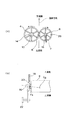
【解決手段】 定着装置2は、互いに圧接して回転する加熱ローラおよび加圧ローラ8によって形成されるニップ部で用紙を挟持搬送しながら加熱および加圧することによりトナー画像を用紙に定着する。加圧ローラ8のボス16は、アームフレーム18a,18bに固定されたベアリング20a,20bに回転可能に支持されている。ベアリング20a,20bは、その中心軸線CBがボス16の回転中心軸線CPと略同一平面内に位置し且つ中心軸線CBがベアリング外側において用紙の搬送方向に関してニップ部の下流側に位置するようアームフレーム18a,18bに固定される。
【選択図】図3
Description
互いに圧接して回転する一対の回転体によって形成されるニップ部で用紙を挟持搬送しながら加熱および加圧することによりトナー画像を用紙に定着する定着装置において、
回転体の少なくとも一方のボスは、支持部材に支持されたベアリングに回転可能に支持されており、
上記ベアリングは、その中心軸線がボスの回転中心軸線と略同一平面内に位置し且つベアリングの中心軸線がベアリング外側において用紙の搬送方向に関してニップ部の下流側に位置する向きに支持される、
ことを特徴とする。
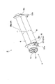
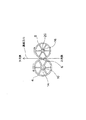
図1,2は、本発明に係る定着装置の第1の実施形態を示す。この定着装置2は、内部に加熱用のハロゲンヒータ(図示せず)を有する加熱ローラ4、および、加熱ローラ4と圧接して用紙が通過するニップ部6を形成する加圧ローラ8を備える。加熱ローラ4のボス10は、メインフレーム(図示せず)に固定された一対のベアリング14に回転可能に支持されている。ボス10は、図示しない回転駆動源に駆動連結されている。加圧ローラ8のボス16は、一対のアームフレーム18(18a,18b)(支持部材)に固定された一対のベアリング20に回転可能に支持されている。アームフレーム18a,18bは、メインフレームに固定された一対のピン22a,22bを介してメインフレームに回動可能に支持されている。アームフレーム18a,18bは、図示しない付勢手段(例えばバネ)によりピン22a,22bを中心として所定の回転方向に付勢されており、これにより加圧ローラ8が加熱ローラ4に圧接するようになっている。
図6は、本発明に係る定着装置の第2の実施形態において、加圧ローラの支持機構の詳細図を示す。本実施形態では、第1の実施形態と同様に、アームフレーム18は、加圧ローラ8端面のニップ部6下流側に対向する部分が、加圧ローラ8端面のニップ部6上流側部分に対向する部分に比べて加圧ローラ端面側に位置するように形成されているが、ベアリング20は、アームフレームに固定されてない状態でアームフレームのベアリング穴に隙間嵌合されている。したがって、定着装置を組み立てた際に、ベアリングは、その中心軸線CBがいずれの方向にも向く可能性がある。その結果、加圧ローラ8を回転させると、図6のようにベアリング20が上流側に比べて下流側で加圧ローラ端面側に位置していれば、ベアリングは加圧ローラに近づく方向にスラスト力を受ける。逆に、ベアリング20が下流側に比べて上流側で加圧ローラ端面側に位置していれば、ベアリングは加圧ローラから離れる方向にスラスト力を受ける。しかしながら、ベアリング20は、アームフレーム18に押し付けられ(アームフレーム18に当接し)、その結果、図6に示すように上流側に比べて下流側で加圧ローラ端面側に位置するようにその傾きが矯正される。その後、ベアリング20は、加圧ローラ8に向かう方向にスラスト力を受けることになり、第1の実施形態と同様に異音の発生が防止される。
4 加熱ローラ
6 ニップ部
8 加圧ローラ
10 ボス
14 ベアリング
16 ボス
18 アームフレーム(支持部材)
20 ベアリング
CP 加圧ローラの回転中心軸線
CB ベアリングの中心軸線
Claims (3)
- 互いに圧接して回転する一対の回転体によって形成されるニップ部で用紙を挟持搬送しながら加熱および加圧することによりトナー画像を用紙に定着する定着装置において、
回転体の少なくとも一方のボスは、支持部材に支持されたベアリングに回転可能に支持されており、
上記ベアリングは、その中心軸線がボスの回転中心軸線と略同一平面内に位置し且つベアリングの中心軸線がベアリング外側において用紙の搬送方向に関してニップ部の下流側に位置する向きに支持される、
ことを特徴とする定着装置。 - 支持部材は、ベアリングの外輪を該部材に固定した状態で上記向きに支持するように形成されていることを特徴とする請求項1記載の定着装置。
- 上記ベアリングは、その外輪が支持部材に非固定状態で支持部材に支持されており、
支持部材は、ベアリングの外輪が支持部材に当接するとベアリングを上記向きに支持するように形成されていることを特徴とする請求項1記載の定着装置。
Priority Applications (1)
| Application Number | Priority Date | Filing Date | Title |
|---|---|---|---|
| JP2004286661A JP4561284B2 (ja) | 2004-09-30 | 2004-09-30 | 定着装置 |
Applications Claiming Priority (1)
| Application Number | Priority Date | Filing Date | Title |
|---|---|---|---|
| JP2004286661A JP4561284B2 (ja) | 2004-09-30 | 2004-09-30 | 定着装置 |
Publications (2)
| Publication Number | Publication Date |
|---|---|
| JP2006098902A true JP2006098902A (ja) | 2006-04-13 |
| JP4561284B2 JP4561284B2 (ja) | 2010-10-13 |
Family
ID=36238765
Family Applications (1)
| Application Number | Title | Priority Date | Filing Date |
|---|---|---|---|
| JP2004286661A Expired - Fee Related JP4561284B2 (ja) | 2004-09-30 | 2004-09-30 | 定着装置 |
Country Status (1)
| Country | Link |
|---|---|
| JP (1) | JP4561284B2 (ja) |
Cited By (1)
| Publication number | Priority date | Publication date | Assignee | Title |
|---|---|---|---|---|
| JP2016143004A (ja) * | 2015-02-04 | 2016-08-08 | キヤノン株式会社 | 現像装置、プロセスカートリッジおよび画像形成装置 |
Citations (6)
| Publication number | Priority date | Publication date | Assignee | Title |
|---|---|---|---|---|
| JPS5823356U (ja) * | 1981-08-08 | 1983-02-14 | 京セラミタ株式会社 | 静電写真複写機における定着装置 |
| JPH01201690A (ja) * | 1988-02-08 | 1989-08-14 | Olympus Optical Co Ltd | ローラ定着装置 |
| JPH05232831A (ja) * | 1991-12-27 | 1993-09-10 | Tokyo Electric Co Ltd | 定着装置 |
| JPH0822210A (ja) * | 1994-07-08 | 1996-01-23 | Canon Inc | 定着装置 |
| JP2001249568A (ja) * | 2000-03-07 | 2001-09-14 | Konica Corp | 画像形成装置の定着装置 |
| JP2003186338A (ja) * | 2001-12-14 | 2003-07-04 | Kyocera Mita Corp | 定着装置 |
-
2004
- 2004-09-30 JP JP2004286661A patent/JP4561284B2/ja not_active Expired - Fee Related
Patent Citations (6)
| Publication number | Priority date | Publication date | Assignee | Title |
|---|---|---|---|---|
| JPS5823356U (ja) * | 1981-08-08 | 1983-02-14 | 京セラミタ株式会社 | 静電写真複写機における定着装置 |
| JPH01201690A (ja) * | 1988-02-08 | 1989-08-14 | Olympus Optical Co Ltd | ローラ定着装置 |
| JPH05232831A (ja) * | 1991-12-27 | 1993-09-10 | Tokyo Electric Co Ltd | 定着装置 |
| JPH0822210A (ja) * | 1994-07-08 | 1996-01-23 | Canon Inc | 定着装置 |
| JP2001249568A (ja) * | 2000-03-07 | 2001-09-14 | Konica Corp | 画像形成装置の定着装置 |
| JP2003186338A (ja) * | 2001-12-14 | 2003-07-04 | Kyocera Mita Corp | 定着装置 |
Cited By (1)
| Publication number | Priority date | Publication date | Assignee | Title |
|---|---|---|---|---|
| JP2016143004A (ja) * | 2015-02-04 | 2016-08-08 | キヤノン株式会社 | 現像装置、プロセスカートリッジおよび画像形成装置 |
Also Published As
| Publication number | Publication date |
|---|---|
| JP4561284B2 (ja) | 2010-10-13 |
Similar Documents
| Publication | Publication Date | Title |
|---|---|---|
| US9829841B2 (en) | Fixing device and image forming apparatus including a fixing device | |
| CN106842867B (zh) | 定影装置 | |
| JP6141112B2 (ja) | 画像加熱装置 | |
| JP2008224833A (ja) | 分離装置、定着装置、及び、画像形成装置 | |
| US9395685B2 (en) | Fixing device provided with positioning member capable of positioning heating unit with respect to pressure roller | |
| JP2016071127A (ja) | 定着装置 | |
| JP4561284B2 (ja) | 定着装置 | |
| JP2010217587A (ja) | 軸受け構造、及び定着装置 | |
| CN104570672B (zh) | 定影装置及图像形成装置 | |
| JP7143138B2 (ja) | 定着装置 | |
| JP5361645B2 (ja) | 定着装置 | |
| US11156947B2 (en) | Fixing device and image forming apparatus | |
| CN107728449B (zh) | 定影装置及具备该定影装置的图像形成装置 | |
| JP3940024B2 (ja) | 定着装置 | |
| JP4732196B2 (ja) | ベルト定着器 | |
| JPH09152800A (ja) | 定着装置 | |
| JP3710407B2 (ja) | シート給送装置及びこれを備えた画像形成装置 | |
| JP2024056184A (ja) | 加熱装置、定着装置及び画像形成装置 | |
| JP3655254B2 (ja) | 定着装置およびそれを用いた画像形成装置 | |
| JPH0990791A (ja) | 定着装置 | |
| JP5737613B2 (ja) | 定着装置、及び画像形成装置 | |
| JP2006103871A (ja) | 記録媒体の搬送装置、定着装置、及び画像形成装置 | |
| JP2005107135A (ja) | 画像形成装置 | |
| JP2007033535A (ja) | 定着装置 | |
| JP6525610B2 (ja) | 定着装置及び記録材搬送装置 |
Legal Events
| Date | Code | Title | Description |
|---|---|---|---|
| A621 | Written request for application examination |
Free format text: JAPANESE INTERMEDIATE CODE: A621 Effective date: 20060922 |
|
| A977 | Report on retrieval |
Free format text: JAPANESE INTERMEDIATE CODE: A971007 Effective date: 20090401 |
|
| A131 | Notification of reasons for refusal |
Free format text: JAPANESE INTERMEDIATE CODE: A131 Effective date: 20090602 |
|
| A521 | Written amendment |
Free format text: JAPANESE INTERMEDIATE CODE: A523 Effective date: 20090803 |
|
| A131 | Notification of reasons for refusal |
Free format text: JAPANESE INTERMEDIATE CODE: A131 Effective date: 20100119 |
|
| A521 | Written amendment |
Free format text: JAPANESE INTERMEDIATE CODE: A523 Effective date: 20100323 |
|
| TRDD | Decision of grant or rejection written | ||
| A01 | Written decision to grant a patent or to grant a registration (utility model) |
Free format text: JAPANESE INTERMEDIATE CODE: A01 Effective date: 20100706 |
|
| A01 | Written decision to grant a patent or to grant a registration (utility model) |
Free format text: JAPANESE INTERMEDIATE CODE: A01 |
|
| A61 | First payment of annual fees (during grant procedure) |
Free format text: JAPANESE INTERMEDIATE CODE: A61 Effective date: 20100719 |
|
| FPAY | Renewal fee payment (event date is renewal date of database) |
Free format text: PAYMENT UNTIL: 20130806 Year of fee payment: 3 |
|
| R150 | Certificate of patent or registration of utility model |
Free format text: JAPANESE INTERMEDIATE CODE: R150 |
|
| S111 | Request for change of ownership or part of ownership |
Free format text: JAPANESE INTERMEDIATE CODE: R313111 |
|
| R350 | Written notification of registration of transfer |
Free format text: JAPANESE INTERMEDIATE CODE: R350 |
|
| LAPS | Cancellation because of no payment of annual fees |