JP2006108332A - 圧電トランス - Google Patents
圧電トランス Download PDFInfo
- Publication number
- JP2006108332A JP2006108332A JP2004292015A JP2004292015A JP2006108332A JP 2006108332 A JP2006108332 A JP 2006108332A JP 2004292015 A JP2004292015 A JP 2004292015A JP 2004292015 A JP2004292015 A JP 2004292015A JP 2006108332 A JP2006108332 A JP 2006108332A
- Authority
- JP
- Japan
- Prior art keywords
- piezoelectric transformer
- case
- gold thread
- box
- wire
- Prior art date
- Legal status (The legal status is an assumption and is not a legal conclusion. Google has not performed a legal analysis and makes no representation as to the accuracy of the status listed.)
- Granted
Links
Images








Landscapes
- Piezo-Electric Or Mechanical Vibrators, Or Delay Or Filter Circuits (AREA)
- Dc-Dc Converters (AREA)
Abstract
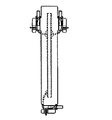
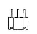
【解決手段】 底面側6Aが開口した箱形に形成され、前記底面側に伸長する一次側、二次側それぞれのピン端子8A,8B,8Cを有する箱形のケース6と、該箱形のケース6内に縦置きに収納される圧電トランス本体1とを有し、ピン端子8A,8B,8Cがそれぞれ圧電トランス本体1に金糸線5を介して接続されている。
【選択図】 図7
Description
2 圧電磁器板
3 電極
4 端部
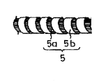
5 金糸線
5a 芯線
5b 銅箱
6 ケース
6a 側部
6b側部
7a 端子植設部
7b 端子植設部
7c 端子植設部
8A 端子
8B 端子
8C 端子
Claims (5)
- 底面側が開口した箱形に形成され、前記底面側に伸長する一次側、二次側それぞれのピン端子を有する箱形のケースと、該箱形のケース内に縦置きに収納される圧電トランス本体とを有し、前記ピン端子にリード線を介して前記圧電トランス本体が接続されていることを特徴とする圧電トランス。
- 請求項1記載の圧電トランスが前記ピン端子を基板に設けられた穴に挿入することにより該基板上に実装されることを特徴とする圧電トランスの実装構造。
- 請求項1又は2記載の圧電トランスにおいて、前記リード線として金糸線を用い、前記箱形のケースの側部に溝部を設けたことを特徴とする圧電トランス。
- 請求項1乃至3記載の圧電トランスにおいて、前記リード線として金糸線を用い、前記ケース内に収納されて該金糸線の一端が接続された前記圧電トランス本体から前記ケースの外部に引き出された前記金糸線の他端部を前記ピン端子に絡げた上で半田付けする圧電トランスにおいて、前記ピン端子の近傍に前記絡げられた金糸線の余長部分を仮固定するための溝部を設けたことを特徴とする圧電トランス。
- 請求項1乃至4記載の圧電トランスにおいて、前記箱形のケースにおける前記圧電トランス本体の収納面の前記圧電トランス本体の振動の節に対応する位置に前記圧電トランス本体を支持する内側突起を設けたことを特徴とする圧電トランス。
Priority Applications (1)
| Application Number | Priority Date | Filing Date | Title |
|---|---|---|---|
| JP2004292015A JP4583130B2 (ja) | 2004-10-04 | 2004-10-04 | 圧電トランス |
Applications Claiming Priority (1)
| Application Number | Priority Date | Filing Date | Title |
|---|---|---|---|
| JP2004292015A JP4583130B2 (ja) | 2004-10-04 | 2004-10-04 | 圧電トランス |
Publications (2)
| Publication Number | Publication Date |
|---|---|
| JP2006108332A true JP2006108332A (ja) | 2006-04-20 |
| JP4583130B2 JP4583130B2 (ja) | 2010-11-17 |
Family
ID=36377709
Family Applications (1)
| Application Number | Title | Priority Date | Filing Date |
|---|---|---|---|
| JP2004292015A Expired - Fee Related JP4583130B2 (ja) | 2004-10-04 | 2004-10-04 | 圧電トランス |
Country Status (1)
| Country | Link |
|---|---|
| JP (1) | JP4583130B2 (ja) |
Cited By (10)
| Publication number | Priority date | Publication date | Assignee | Title |
|---|---|---|---|---|
| JP2009088311A (ja) * | 2007-10-01 | 2009-04-23 | Tamura Seisakusho Co Ltd | 圧電トランス |
| JP2009094222A (ja) * | 2007-10-05 | 2009-04-30 | Tamura Seisakusho Co Ltd | 圧電トランス |
| JP2009130311A (ja) * | 2007-11-28 | 2009-06-11 | Tamura Seisakusho Co Ltd | 圧電トランスの実装方法及び圧電トランス |
| JP2009141212A (ja) * | 2007-12-07 | 2009-06-25 | Tamura Seisakusho Co Ltd | 圧電トランス |
| WO2009098934A1 (ja) * | 2008-02-05 | 2009-08-13 | Tamura Corporation | 圧電トランス装置 |
| JP2009188021A (ja) * | 2008-02-04 | 2009-08-20 | Tamura Seisakusho Co Ltd | 圧電トランス |
| USD605114S1 (en) | 2007-12-20 | 2009-12-01 | Tamura Corporation | Piezoelectric transformer |
| US8639133B2 (en) | 2008-12-01 | 2014-01-28 | Canon Kabushiki Kaisha | Power supply apparatus and image forming apparatus |
| JP2015015460A (ja) * | 2013-06-03 | 2015-01-22 | 株式会社タムラ製作所 | 電子部品モジュール |
| US10671009B2 (en) | 2017-02-13 | 2020-06-02 | Canon Kabushiki Kaisha | Printed circuit board mounting piezoelectric transformer |
Citations (7)
| Publication number | Priority date | Publication date | Assignee | Title |
|---|---|---|---|---|
| JPS6063928U (ja) * | 1983-10-07 | 1985-05-07 | 池田電機株式会社 | 放電灯用安定器装置 |
| JPS6177377A (ja) * | 1984-09-21 | 1986-04-19 | Dx Antenna Co Ltd | 発光ダイオ−ドの取付方法 |
| JPH0622861A (ja) * | 1992-07-06 | 1994-02-01 | Matsushita Electric Ind Co Ltd | 電気調理器用温度センサー |
| JPH0864884A (ja) * | 1994-08-22 | 1996-03-08 | Tamura Seisakusho Co Ltd | 圧電トランス |
| JPH0888420A (ja) * | 1994-09-16 | 1996-04-02 | Toto Ltd | 圧電トランスの実装構造 |
| JPH0936451A (ja) * | 1995-07-20 | 1997-02-07 | Toto Ltd | 圧電トランスの実装構造 |
| JP2000133856A (ja) * | 1998-10-27 | 2000-05-12 | Toto Ltd | 圧電トランス |
-
2004
- 2004-10-04 JP JP2004292015A patent/JP4583130B2/ja not_active Expired - Fee Related
Patent Citations (7)
| Publication number | Priority date | Publication date | Assignee | Title |
|---|---|---|---|---|
| JPS6063928U (ja) * | 1983-10-07 | 1985-05-07 | 池田電機株式会社 | 放電灯用安定器装置 |
| JPS6177377A (ja) * | 1984-09-21 | 1986-04-19 | Dx Antenna Co Ltd | 発光ダイオ−ドの取付方法 |
| JPH0622861A (ja) * | 1992-07-06 | 1994-02-01 | Matsushita Electric Ind Co Ltd | 電気調理器用温度センサー |
| JPH0864884A (ja) * | 1994-08-22 | 1996-03-08 | Tamura Seisakusho Co Ltd | 圧電トランス |
| JPH0888420A (ja) * | 1994-09-16 | 1996-04-02 | Toto Ltd | 圧電トランスの実装構造 |
| JPH0936451A (ja) * | 1995-07-20 | 1997-02-07 | Toto Ltd | 圧電トランスの実装構造 |
| JP2000133856A (ja) * | 1998-10-27 | 2000-05-12 | Toto Ltd | 圧電トランス |
Cited By (11)
| Publication number | Priority date | Publication date | Assignee | Title |
|---|---|---|---|---|
| JP2009088311A (ja) * | 2007-10-01 | 2009-04-23 | Tamura Seisakusho Co Ltd | 圧電トランス |
| JP2009094222A (ja) * | 2007-10-05 | 2009-04-30 | Tamura Seisakusho Co Ltd | 圧電トランス |
| JP2009130311A (ja) * | 2007-11-28 | 2009-06-11 | Tamura Seisakusho Co Ltd | 圧電トランスの実装方法及び圧電トランス |
| JP2009141212A (ja) * | 2007-12-07 | 2009-06-25 | Tamura Seisakusho Co Ltd | 圧電トランス |
| USD605114S1 (en) | 2007-12-20 | 2009-12-01 | Tamura Corporation | Piezoelectric transformer |
| JP2009188021A (ja) * | 2008-02-04 | 2009-08-20 | Tamura Seisakusho Co Ltd | 圧電トランス |
| WO2009098934A1 (ja) * | 2008-02-05 | 2009-08-13 | Tamura Corporation | 圧電トランス装置 |
| US8639133B2 (en) | 2008-12-01 | 2014-01-28 | Canon Kabushiki Kaisha | Power supply apparatus and image forming apparatus |
| JP2015015460A (ja) * | 2013-06-03 | 2015-01-22 | 株式会社タムラ製作所 | 電子部品モジュール |
| US10671009B2 (en) | 2017-02-13 | 2020-06-02 | Canon Kabushiki Kaisha | Printed circuit board mounting piezoelectric transformer |
| US11307525B2 (en) | 2017-02-13 | 2022-04-19 | Canon Kabushiki Kaisha | Printed circuit board mounting piezoelectric transformer |
Also Published As
| Publication number | Publication date |
|---|---|
| JP4583130B2 (ja) | 2010-11-17 |
Similar Documents
| Publication | Publication Date | Title |
|---|---|---|
| JP3831368B2 (ja) | リーケージトランス | |
| JP4583130B2 (ja) | 圧電トランス | |
| JP2004179173A (ja) | 線材保持具 | |
| JP2005310812A (ja) | コイル部品 | |
| US20040026123A1 (en) | Apparatus for fixing bobbin to printed circuit board for use in transformer | |
| KR100476556B1 (ko) | 압전트랜스 장치, 압전트랜스 하우징 및 그 제조방법 | |
| JP2005136708A (ja) | スピーカ装置及びその製造方法 | |
| JP5963044B2 (ja) | コアケースユニットおよびコイル部品 | |
| US5245497A (en) | Transformer | |
| US6262518B1 (en) | Housing for piezoelectric transformer device | |
| JP2005203478A (ja) | チップ形アルミ電解コンデンサ | |
| JP2005191162A (ja) | リジットフレキシブル配線基板、及びそれを使用した電子機器 | |
| JPH1079583A (ja) | 電気コードの保持構造 | |
| JP4788376B2 (ja) | 面実装型トランス | |
| JP4490363B2 (ja) | 電気機器 | |
| JP2020155661A (ja) | コイル部品、電子装置 | |
| JP4775093B2 (ja) | 高電圧トランス | |
| JPH11242950A (ja) | 電源回路用端子接続装置 | |
| JP4153191B2 (ja) | 圧電トランス | |
| JP2003297652A (ja) | 小形巻線部品 | |
| JPH0864884A (ja) | 圧電トランス | |
| JPS645855Y2 (ja) | ||
| KR100279376B1 (ko) | 압전트랜스의 기판 결합장치 | |
| JP2007258484A (ja) | 基板搭載型トランス及びそれ用の台座 | |
| JPH1154066A (ja) | 偏向ヨーク装置 |
Legal Events
| Date | Code | Title | Description |
|---|---|---|---|
| A621 | Written request for application examination |
Free format text: JAPANESE INTERMEDIATE CODE: A621 Effective date: 20060828 |
|
| A131 | Notification of reasons for refusal |
Free format text: JAPANESE INTERMEDIATE CODE: A131 Effective date: 20100525 |
|
| A977 | Report on retrieval |
Free format text: JAPANESE INTERMEDIATE CODE: A971007 Effective date: 20100527 |
|
| A521 | Request for written amendment filed |
Free format text: JAPANESE INTERMEDIATE CODE: A523 Effective date: 20100724 |
|
| TRDD | Decision of grant or rejection written | ||
| A01 | Written decision to grant a patent or to grant a registration (utility model) |
Free format text: JAPANESE INTERMEDIATE CODE: A01 Effective date: 20100817 |
|
| A01 | Written decision to grant a patent or to grant a registration (utility model) |
Free format text: JAPANESE INTERMEDIATE CODE: A01 |
|
| A61 | First payment of annual fees (during grant procedure) |
Free format text: JAPANESE INTERMEDIATE CODE: A61 Effective date: 20100831 |
|
| R150 | Certificate of patent or registration of utility model |
Ref document number: 4583130 Country of ref document: JP Free format text: JAPANESE INTERMEDIATE CODE: R150 |
|
| FPAY | Renewal fee payment (event date is renewal date of database) |
Free format text: PAYMENT UNTIL: 20130910 Year of fee payment: 3 |
|
| LAPS | Cancellation because of no payment of annual fees |