JP2006121237A - Electronic device, connection device, remote operation system, and remote operation method - Google Patents
Electronic device, connection device, remote operation system, and remote operation method Download PDFInfo
- Publication number
- JP2006121237A JP2006121237A JP2004304877A JP2004304877A JP2006121237A JP 2006121237 A JP2006121237 A JP 2006121237A JP 2004304877 A JP2004304877 A JP 2004304877A JP 2004304877 A JP2004304877 A JP 2004304877A JP 2006121237 A JP2006121237 A JP 2006121237A
- Authority
- JP
- Japan
- Prior art keywords
- state
- electronic device
- operation mode
- connection
- restart command
- Prior art date
- Legal status (The legal status is an assumption and is not a legal conclusion. Google has not performed a legal analysis and makes no representation as to the accuracy of the status listed.)
- Granted
Links
Images

Landscapes
- Details Of Television Systems (AREA)
- Studio Devices (AREA)
- Selective Calling Equipment (AREA)
Abstract
【課題】制御プログラムの構造の単純化を図ることが可能な電子機器、接続機器、遠隔操作システム、並びに、遠隔操作方法を提供する。
【解決手段】外部接続機器3と接続状態で用いられる第1の動作モードと、外部接続機器3と非接続状態で用いられる第2の動作モードとを有カメラ本体2と、カメラ本体2の動作状態が第2の動作モードにおける特定の状態の場合、再起動の指令を制限して(リセット信号RESETの出力を抑止して)、カメラ本体2の動作状態を上記第2のモード特定の状態に維持させ、カメラ本体2の動作状熊が上記特定の状態でない場合、リセット信号RESETを端子34を通して信号ライン44に転送してカメラ本体2を再起動させ第1の動作モードに遷移させる外部接続機器3を有する。
【選択図】 図1
An electronic device, a connection device, a remote operation system, and a remote operation method capable of simplifying the structure of a control program are provided.
A camera body having a first operation mode used in a connected state with an external connection device and a second operation mode used in a non-connected state with the external connection device, and the operation of the camera body. When the state is a specific state in the second operation mode, the restart command is limited (suppressing the output of the reset signal RESET), and the operation state of the camera body 2 is changed to the second mode specific state. When the operation state bear of the camera body 2 is not in the specific state, the external connection device that transfers the reset signal RESET to the signal line 44 through the terminal 34 to restart the camera body 2 and shift to the first operation mode. 3.
[Selection] Figure 1
Description
本発明は、デジタルカメラ等の多機能化された電子機器、この電子機器に接続可能で電子機器を遠隔可能な接続機器、およびこれら電子機器および接続機器を備えた遠隔操作システム、並びに遠隔操作方法に関するものである。 The present invention relates to a multifunctional electronic device such as a digital camera, a connection device that can be connected to the electronic device and can remotely control the electronic device, a remote operation system including the electronic device and the connection device, and a remote operation method. It is about.
従来より、複数のモードを有する電子機器が他の機器と接続されたことを検知すると、自動的に接続された機器との連携に適したモードに自動的に遷移する、デジタルカメラやビデオカメラ等が、以下に第1から第5の器として、種々提案されている。 Conventionally, when it is detected that an electronic device having a plurality of modes is connected to another device, a digital camera, a video camera, or the like that automatically transitions to a mode suitable for cooperation with the connected device However, various proposals have been made as first to fifth vessels below.
第1の機器は、USB接続を検知すると専用のモードに設定するものである。また、USBケーブル接続状態で機器の電源がオンとなると、PC接続モードで起動する。 The first device sets a dedicated mode when it detects a USB connection. When the device is turned on with the USB cable connected, it starts in the PC connection mode.
第2の機器は、複数の動作モードを備えたビデオカメラにて、接続されたアクセサリーに適した動作モードを自動的に選択するものである。 The second device automatically selects an operation mode suitable for the connected accessory in a video camera having a plurality of operation modes.
第3の機器は、ビデオカメラとステーションとが接続可能なものであって、ステーションの接続を検知してモードを変更するものである。 The third device can connect the video camera and the station, and detects the connection of the station and changes the mode.
第4の機器は、他の機器へ電源電圧を供給する機器において、自機器の電源リセットの際、一定時間遅延して他機器の接続状態を検知するものである。 The fourth device is a device that supplies a power supply voltage to another device, and detects a connection state of the other device with a certain delay when the power of the own device is reset.
第5の機器は、VTRがカメラとチューナ等に接続可能で、接続機器に応じてモードを自動切換するものである(たとえば特許文献1参照)。
上述したように、第1から第5の機器は、複数のモードを有する機器が他の機器と接続されたことを検知すると、自動的に接続された機器との連携に適したモードに自動的に遷移するものであるが、機器の制御プログラムの構造が複雑となる問題がある。
特に、近年のデジタルカメラは多機能化しており、状態管理も複雑になっている。ここにさらに外部機器との接続による状態管理を加えると、その管理は非常に複雑となり、想定しない不具合も発生しやすくなる。
As described above, when the first to fifth devices detect that a device having a plurality of modes is connected to another device, the first to fifth devices automatically enter a mode suitable for cooperation with the connected device. However, there is a problem that the structure of the device control program is complicated.
In particular, digital cameras in recent years have become multifunctional and state management has become complicated. If state management is further performed by connecting to an external device, the management becomes very complicated and unforeseen problems are likely to occur.
本発明の目的は、制御プログラムの構造の単純化を図ることが可能な電子機器、接続機器、遠隔操作システム、並びに、遠隔操作方法を提供することにある。 An object of the present invention is to provide an electronic device, a connected device, a remote operation system, and a remote operation method capable of simplifying the structure of a control program.
本発明の第1の観点は、接続機器と接続可能で、少なくとも上記接続機器と接続状態で用いられる第1の動作モードと、上記接続機器と非接続状態で用いられる第2の動作モードとを有し、少なくとも第1の動作モードに対応した第1のアプリケーションプログラムと第2の動作モードに対応した第2のアプリケーションプログラムとを実行可能な電子機器であって、少なくとも上記接続機器からの再起動の指令を受ける、上記接続機器との信号の送受を行う信号ラインと、上記接続機器の接続を検知する検知手段と、上記信号ラインの信号からの再起動の指令に基づき再起動を行う再起動手段と、上記再起動手段による再起動の際、上記検知手段により上記接続機器の接続が検知された場合には上記第1のアプリケーションプログラムで起動を行って上記第1の動作モードに遷移し、上記検出手段により上記接続機器の非接続が検知された場合には上記第2のアプリケーションプログラムで起動を行って上記第2の動作モードに遷移する第1の制御手段とを有する。 According to a first aspect of the present invention, there is provided a first operation mode that is connectable with a connected device and is used in a connected state with at least the connected device, and a second operation mode used in a disconnected state with the connected device. An electronic device capable of executing at least a first application program corresponding to the first operation mode and a second application program corresponding to the second operation mode, and restarting at least from the connected device A signal line for transmitting / receiving signals to / from the connected device, a detecting means for detecting connection of the connected device, and a restart for restarting based on a restart command from the signal on the signal line And when the connection of the connected device is detected by the detection means at the time of restart by the restart means, the first application program starts To make a transition to the first operation mode, and when the detection means detects that the connected device is not connected, the second application program is activated to make a transition to the second operation mode. First control means.
好適には、上記検知手段により上記接続機器の接続が検知された場合、上記信号ラインを通じて上記接続機器に動作状態を報知する状態報知手段を、さらに有する。 Preferably, when the connection of the connection device is detected by the detection unit, the device further includes a state notification unit that notifies the connection device of the operation state through the signal line.
好適には、上記第1の制御手段は、上記状態報知手段により上記接続機器に動作状態を報知し、報知した動作状態に応じて接続機器からの再起動を制限させる。 Preferably, the first control unit notifies the connected device of an operation state by the state notification unit, and restricts restart from the connected device according to the notified operation state.
好適には、上記信号ラインには、外部電源に接続された信号ラインを含み、上記第1の制御手段は、パワーオン状態で、上記検知手段により上記接続機器の接続を検知すると、一旦パワーオフ処理を行って上記外部電源による充電処理を行い、再起動手段は、上記信号ラインの信号からの再起動の指令に基づき再起動を行う。 Preferably, the signal line includes a signal line connected to an external power source. When the first control unit detects the connection of the connection device by the detection unit in a power-on state, the signal line is temporarily turned off. Processing is performed to perform charging processing by the external power source, and the restarting unit restarts based on a restart command from the signal on the signal line.
好適には、上記信号ラインには、外部電源に接続された信号ラインを含み、上記第1の制御手段は、上記第2の動作モードの特定の状態で、上記検知手段により上記接続機器の接続を検知すると、当該第2の動作モードの特定の状態が解除されてから、一旦パワーオフ処理を行って上記外部電源による充電処理を行い、再起動手段は、上記信号ラインの信号からの再起動の指令に基づき再起動を行う。 Preferably, the signal line includes a signal line connected to an external power source, and the first control unit connects the connection device by the detection unit in a specific state of the second operation mode. Is detected, after the specific state of the second operation mode is released, the power off process is performed once, the charging process by the external power supply is performed, and the restarting means restarts from the signal on the signal line Reboot based on the command.
好適には、上記第1の制御手段、上記接続機器により制御信号が供給されると、当該制御信号に応じた状態遷移を行う。 Preferably, when a control signal is supplied from the first control means and the connected device, state transition is performed according to the control signal.
本発明の第2の観点は、少なくとも接続状態で用いられる第1の動作モードと非接続状態で用いられる第2の動作モードを有する電子機器と接続可能な接続機器であって、上記電子機器へ再起動の指令を送るための再起動指令手段と、少なくとも上記再起動指令手段からの再起動指令を送ると共に上記電子機器の動作状態の報知を受ける、上記電子機器との信号の送受を行う信号ラインと、上記信号ラインから受けた上記電子機器の動作状態の報知により当該電子機器の状態を検知する状態検知手段と、上記状態検知手段により上記電子機器の動作状態が上記第2の動作モードにおける特定の状態の場合、上記再起動指令手段による再起動の指令を制限して上記電子機器の動作状態を上記特定の状態に維持させ、上記電子機器の動作状熊が上記特定の状態でない場合、上記再起動指令手段による再起動を実施し上記電子機器を第1の動作モードで再起動させる第2の制御手段とを有する。 According to a second aspect of the present invention, there is provided a connection device that can be connected to an electronic device having at least a first operation mode used in a connected state and a second operation mode used in a non-connected state. A restart command means for sending a restart command, and a signal for sending / receiving a signal to / from the electronic device, which sends at least a restart command from the restart command means and receives notification of an operating state of the electronic device A state detection unit that detects the state of the electronic device by notification of the operation state of the electronic device received from the signal line, and the operation state of the electronic device in the second operation mode by the state detection unit. In the case of a specific state, the restart command by the restart command means is limited to maintain the operation state of the electronic device in the specific state, and the operation state bear of the electronic device is If not the specific state, and a second control means for restarting the electronic device to implement the restart by the restart command means in the first operating mode.
好適には、上記第2の制御手段は、上記状態検知手段により上記電子機器の動作状態が上記第2の動作モードにおける特定の状態の場合、上記状態検知手段による電源オフの検知を待って、上記再起動指令手段による再起動を実施し上記電子機器を第1の動作モードで再起動させる。 Preferably, when the operation state of the electronic device is a specific state in the second operation mode by the state detection unit, the second control unit waits for detection of power off by the state detection unit, The electronic device is restarted in the first operation mode by restarting by the restart command means.
好適には、上記第2の制御手段は、上記状態検知手段により上記電子機器の動作状態が上記第2の動作モードにおける特定の状態の場合、上記再起動指令手段による再起動の指令を制限して上記電子機器の動作状態を上記特定の状態に維持させると共に、上記状態検知手段による電源オフの検知を待って、上記再起動指令手段による再起動を実施し上記電子機器を第1の動作モードで再起動させる。 Preferably, the second control means limits the restart command by the restart command means when the operation state of the electronic device is a specific state in the second operation mode by the state detection means. The operation state of the electronic device is maintained in the specific state, and after the power detection is detected by the state detection unit, the electronic device is restarted by the restart command unit and the electronic device is set to the first operation mode. To restart.
本発明の第3の観点の遠隔操作システムは、接続機器と、上記接続機器と接続可能で、少なくとも上記接続機器と接続状態で用いられる第1の動作モードと、上記接続機器と非接続状態で用いられる第2の動作モードとを有し、少なくとも第1の動作モードに対応した第1のアプリケーションプログラムと第2の動作モードに対応した第2のアプリケーションプログラムとを実行可能な電子機器と、を有し、上記電子機器は、少なくとも上記接続機器からの再起動の指令を受ける、上記接続機器との信号の送受を行う信号ラインと、上記接続機器の接続を検知する検知手段と、上記信号ラインの信号からの再起動の指令に基づき再起動を行う再起動手段と、上記再起動手段による再起動の際、上記検知手段により上記接続機器の接続が検知された場合には上記第1のアプリケーションプログラムで起動を行って上記第1の動作モードに遷移し、上記検出手段により上記接続機器の非接続が検知された場合には上記第2のアプリケーションプログラムで起動を行って上記第2の動作モードに遷移する第1の制御手段と、を含み、上記接続機器は、上記電子機器へ再起動の指令を送るための再起動指令手段と、少なくとも上記再起動指令手段からの再起動指令を送ると共に上記電子機器の動作状態の報知を受ける、上記電子機器との信号の送受を行う信号ラインと、上記信号ラインから受けた上記電子機器の動作状態の報知により当該電子機器の状態を検知する状態検知手段と、上記状態検知手段により上記電子機器の動作状態が上記第2の動作モードにおける特定の状態の場合、上記再起動指令手段による再起動の指令を制限して上記電子機器の動作状態を上記特定の状態に維持させ、上記電子機器の動作状熊が上記特定の状態でない場合、上記再起動指令手段による再起動を実施し上記電子機器を第1の動作モードで再起動させる第2の制御手段と、を含む。 A remote operation system according to a third aspect of the present invention is connectable with a connection device and the connection device, and is at least in a first operation mode used in a connected state with the connection device and in a non-connection state with the connection device. An electronic device having a second operation mode used and capable of executing at least a first application program corresponding to the first operation mode and a second application program corresponding to the second operation mode; And the electronic device receives at least a restart command from the connection device, transmits a signal line to and from the connection device, detection means for detecting connection of the connection device, and the signal line The restarting means for restarting based on the restart command from the signal of the signal, and when restarting by the restarting means, the detecting means detects the connection of the connected device. In the case of activation, the first application program is activated to transit to the first operation mode. When the detection means detects that the connected device is not connected, activation is performed using the second application program. And a first control means for making a transition to the second operation mode, wherein the connected device includes a restart command means for sending a restart command to the electronic device, and at least the restart command. A signal line for sending and receiving signals to and from the electronic device, and a notification of the operating state of the electronic device received from the signal line. When the state detection means for detecting the state of the electronic device and the operation state of the electronic device is a specific state in the second operation mode by the state detection means, Limiting the restart command by the start command means to maintain the operation state of the electronic device in the specific state, and restarting by the restart command means when the operation state bear of the electronic device is not the specific state And second control means for restarting the electronic device in the first operation mode.
本発明の第4の観点は、接続機器と接続可能で、少なくとも上記接続機器と接続状態で用いられる第1の動作モードと、上記接続機器と非接続状態で用いられる第2の動作モードとを有し、少なくとも第1の動作モードに対応した第1のアプリケーションプログラムと第2の動作モードに対応した第2のアプリケーションプログラムとを実行可能な電子機器を、上記接続機器により遠隔操作する遠隔操作方法であって、上記電子機器に上記接続機器を接続し、上記電子機器の動作状態を上記接続機器に報知し、上記電子機器の動作状態が上記第2の動作モードにおける特定の状態の場合、再起動の指令を制限して上記電子機器の動作状態を上記特定の状態に維持させ、上記電子機器の動作状熊が上記特定の状態でない場合、上記接続機器から電子機器の再起動を実施し上記電子機器を第1の動作モードで再起動させる。 According to a fourth aspect of the present invention, there is provided a first operation mode that is connectable to a connection device and is used in a connection state with at least the connection device, and a second operation mode used in a connection state with the connection device. A remote operation method for remotely operating an electronic device having at least a first application program corresponding to the first operation mode and a second application program corresponding to the second operation mode by the connection device When the connection device is connected to the electronic device, the operation state of the electronic device is notified to the connection device, and the operation state of the electronic device is a specific state in the second operation mode, If the operation state of the electronic device is not in the specific state by restricting the start command and maintaining the operation state of the electronic device in the specific state, the connection device Implementing child restart device to restart the electronic device in the first operating mode.
本発明によれば、複雑な状態管理を単純化することができ、制御プログラムの構造の単純化を図ることができる。 According to the present invention, complicated state management can be simplified, and the structure of the control program can be simplified.
以下、本発明の実施形態を図面に関連付けて説明する。 Hereinafter, embodiments of the present invention will be described with reference to the drawings.
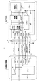
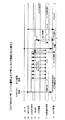
図1は、本発明に係る電子機器および接続機器を採用した遠隔操作システムの一実施形態を示す構成図である。 FIG. 1 is a configuration diagram showing an embodiment of a remote operation system employing an electronic device and a connection device according to the present invention.
本実施形態においては、電子機器はデジタルカメラであるものとするカメラシステムを例に説明する。 In the present embodiment, a camera system in which the electronic device is a digital camera will be described as an example.
本遠隔操作カメラシステム1は、図1に示すように、デジタルカメラ本体(以下、単にカメラ本体という)2、外部接続機器3、および複数の信号ラインを含む接続ケーブル4を主構成要素として有している。
As shown in FIG. 1, the remote
本実施形態のカメラシステム1においては、カメラ本体2は単体で、通常の撮像処理でファイルの書き込み処理等を行うことが可能である。カメラ本体2に外部接続機器3を接続した場合、カメラ本体2に外部接続機器3からの操作のみ受け付ける特殊なモードを用意し、外部接続機器3が接続された場合、外部接続機器3からのカメラハードリセット(再起動指令)によるリセット動作からのみこのモードに遷移するようにすることでこの複雑な状態管理を単純化している。
また、なんらかの理由により、カメラがハングアップ等を起こし、外部接続機器3からの通信を受け付けなくなってしまった状態でも、外部接続機器3からこのハードリセット(再起動指令)をかけることによって確実にリカバリー動作をすることができる。特に外部接続機器3により遠隔操作するような場合、カメラがハングアップしたりすると、通常はカメラのあるところまで行き、リカバリー動作させなければならないが、このような仕組みとすることで、カメラ本体2から離れた場所にいても確実に外部接続機器を通じてリカバリー動作が実現でき、より信頼性の高いシステムを実現している。
また、カメラ本体2を、通常は外部接続機器との接続をせず、通常のカメラとして使用するようなシステムでは、ユーザーがカメラの状態を気にすることなく自由に着脱を行っても問題ないようにする必要がある。
外部機器がカメラ側のハードリセットをかけるこのシステムにおいては、たとえばカメラが記憶媒体のデータを読み込んでいたり、書き込んでいたりしている最中に外部機器と接続し、これを受けて外部機器がハードリセットをかけてしまうと、記憶媒体のデータもしくは記憶媒体そのものを壊してしまう可能性もある。
本実施形態においては、外部接続機器3がカメラ本体2の状態を見てハードリセットをかけるかどうかを判断することにより、そのような不具合も防止することによって、ユーザーの使い勝手を向上することができるように構成される。
In the
In addition, even if the camera hangs up for some reason and no longer accepts communications from the external device 3, it can be reliably recovered by issuing a hard reset (restart command) from the external device 3. Can act. In particular, when remote control is performed by the external connection device 3, when the camera hangs up, it is usually necessary to go to a place where the camera is located and to perform a recovery operation. Even if you are away from your home, you can reliably perform recovery operations through externally connected devices, thus realizing a more reliable system.
Further, in a system in which the camera body 2 is normally used as a normal camera without being connected to an external device, there is no problem even if the user freely attaches and detaches without worrying about the state of the camera. It is necessary to do so.
In this system in which the external device performs a hard reset on the camera side, for example, the camera is connected to the external device while the camera is reading or writing data on the storage medium, and the external device receives the hardware. If the reset is applied, there is a possibility that the data of the storage medium or the storage medium itself is destroyed.
In the present embodiment, the user-friendliness can be improved by preventing such problems by determining whether or not the external connection device 3 performs a hard reset by looking at the state of the camera body 2. Configured as follows.
以下、カメラシステム1、電子機器としてのカメラ本体2、外部接続機器3、および接続ケーブル4の具体的な構成および各部機能について順を追って説明する。
Hereinafter, a specific configuration and functions of each part of the
カメラシステム1は、カメラ本体2に外部接続機器3を、複数の信号線からなる物理的な接続ケーブル4で接続し、外部接続機器3からの信号により、撮影などの操作が可能なカメラシステムとして構成される。
The
接続ケーブル4には、複数の信号ライン41〜46を含む。
信号ライン41は、外部接続機器3側からカメラ本体2に直流電源電圧DC INを供給するためのラインである。
信号ライン42は、グランドGNDラインである。
信号ライン43は、カメラ本体2がパワーオンの状態にあるかパワーオフの状態にあるかをカメラ本体2から外部接続機器3側に報知するための信号CAM POWERの転送ラインである。
信号ライン44は、外部接続機器3からカメラ本体2に対しての再起動指令であるリセット信号RESETの転送ラインである。
信号ライン45は、セットトップボックス(STB)等の外部接続機器3がセットされた場合に、外部接続機器3(STB)によりカメラ本体2をコントロールするために外部接続機器3からカメラ本体2に信号BOX SETの転送ラインである。
信号ライン46は、カメラ本体2と外部接続機器3と、いわゆるUSB通信等を行うためのバスラインである。
The connection cable 4 includes a plurality of
The
The
The
The
The
The
たとえば接続ケーブル4の各信号ライン41〜46の一端は、あらかじめ外部接続機器3の入出力端子T31〜T36に接続してあり、他端側に設けたコネクタ47をカメラ本体の被接続部21に接続することにより、外部接続機器3をカメラ本体2に接続することができる。
信号ライン41の一端が外部接続機器3の端子T31に接続され、他端がコネクタ47が接続時にカメラ本体2の端子T21に接続される。
信号ライン42の一端が外部接続機器3の端子T32に接続され、他端がコネクタ47が接続時にカメラ本体2の端子T22に接続される。
信号ライン43の一端が外部接続機器3の端子T33に接続され、他端がコネクタ47が接続時にカメラ本体2の端子T23に接続される。
信号ライン44の一端が外部接続機器3の端子T34に接続され、他端がコネクタ47が接続時にカメラ本体2の端子T24に接続される。
信号ライン45の一端が外部接続機器3の端子T35に接続され、他端がコネクタ47が接続時にカメラ本体2の端子T25に接続される。
信号ライン45の一端が外部接続機器3の端子T36に接続され、他端がコネクタ47が接続時にカメラ本体2の端子T26に接続される。
For example, one end of each
One end of the
One end of the
One end of the
One end of the
One end of the
One end of the
カメラシステム1においては、基本的に外部接続機器3がカメラ本体2に接続されているときに、信号ライン44を通して、リセット信号RESETをカメラ本体2に送信し、カメラ本体2にハード的なリセット動作を行わせる。
カメラ本体2は、接続ケーブル4により外部接続機器3が接続された場合、信号ライン45のBOX SET信号を受けて、外部接続機器3と接続されたことを検知し、カメラ本体2は外部接続機器3が接続されたことを検知した場合、カメラ動作状態を電源オフ状態に遷移させる。
また、カメラ本体2は、カメラ動作中に外部接続機器接続3が接続されたことを検知した場合であって、リセット動作による再起動の際、外部機器接続検知信号である信号ライン45のBOX SET信号の状態を読み、外部接続機器3が接続されていると判断した場合は、外部接続機器3からの操作により動作する第1の動作モードで起動する。
カメラ本体2は、信号ライン46を通して、カメラ本体2の動作状態を外部接続機器3が検知するためのカメラ動作状態検知信号を転送し、外部接続機器3は接続されたカメラ本体3を再起動(初期化)する際、受信したカメラ動作状態検知信号の状態によりカメラ本体3が電源オフ状態にあることを検知して、リセット信号RESTEを信号ライン44に送信する。
また、外部接続機器3は、接続されたカメラ本体2を初期化する際、カメラ動作状態検知信号の状態によりカメラ本体2が動作状態にある場合は電源オフ状態になるのを待ってリセット信号RESTEを信号ライン44に送信する。
In the
The camera body 2 is connected to the BOX of the
Further, the camera body 2 detects that the external device connection 3 is connected during the camera operation, and the BOX of the
The camera body 2 transfers a camera operation state detection signal for the external connection device 3 to detect the operation state of the camera body 2 through the
Further, when initializing the connected camera body 2, the external connection device 3 waits for the camera body 2 to be in an operation state according to the state of the camera operation state detection signal, and then waits for the power-off state to be reset. Is transmitted to the
以上の基本的な動作をふまえたカメラ本体2および外部接続機器3の構成および機能についてさらに詳細に説明する。 The configuration and function of the camera body 2 and the external connection device 3 based on the above basic operation will be described in more detail.
カメラ本体2は、基本的に、少なくとも外部接続機器3と接続状態で用いられる第1の動作モードと、外部接続機器3と非接続状態で用いられる第2の動作モードとを有し、少なくとも第1の動作モードに対応した第1のアプリケーションプログラムと第2の動作モードに対応した第2のアプリケーションプログラムとを実行可能に構成されている。
第1の動作モードでは、外部接続機器3を通しての再起動処理や撮影等が行われる。
第2の動作モードでは、通常の撮影動作やファイルの書き込み処理等を行う。第2の動作モードで、これらの撮影動作やファイルの書き込み処理等を行っている状態等が第2の動作モードにおける特定の状態として外部接続機器3により認識される。
The camera body 2 basically has at least a first operation mode used in a connection state with the external connection device 3 and a second operation mode used in a non-connection state with the external connection device 3, and at least a first operation mode. The first application program corresponding to the first operation mode and the second application program corresponding to the second operation mode are configured to be executable.
In the first operation mode, restart processing, photographing, and the like through the external connection device 3 are performed.
In the second operation mode, a normal photographing operation, a file writing process, and the like are performed. In the second operation mode, the state of performing these shooting operations, file writing processing, and the like are recognized by the external device 3 as a specific state in the second operation mode.
カメラ本体2は、図1に示すように、上述した被接続部21に加えて、電池22、切替/充電回路23、電源回路24、第1の制御手段としての第1CPU(CPU1)25、第2CPU(CPU2)26、および機能ブロック27を有する。
As shown in FIG. 1, the camera body 2 includes a
切替/充電回路23は、接続ケーブル4を通して外部接続機器3が接続されていない場合には電池21によるDC電圧を電源回路24に供給し、接続ケーブル4を通して外部接続機器3が接続され、外部接続機器3側から供給される電圧DC INの供給を受けた場合には、電池21の供給電圧から、外部からの電圧DC INの供給に切り替えて電源回路24に供給する。
When the external connection device 3 is not connected through the connection cable 4, the switching / charging
電源回路24は、切替/充電回路23から供給される電圧に応じて、第2CPU26および機能ブロック27に必要な駆動電圧を生成して供給する。
また、電源回路24は、接続ケーブル4の信号ライン43に接続される端子T22にカメラ本体2がパワーオンかパワーオフかを示す信号CAM POWERを出力する。接続ケーブル4が接続された場合、このパワー状態を示す信号CAM POWERは、信号ライン43を通して外部接続機器3に供給され、外部接続機器3はこれによりカメラ本体2が電源オン状態か電源オフ状態かを検知する。すなわち、端子T23は信号ライン43を通じて外部接続機器3にカメラ本体2の動作状態を報知する報知手段として機能する。
The
The
第1CPU25は、カメラ本体2の電源管理を主に行う。電池電圧または外部からの電圧DC INのどちらかが供給されている状態では第1CPU25には常に電圧が供給されている。カメラ本体2が電源オフ状態の場合は、第1CPU25は電源回路24を制御し、第2CPU26および機能ブロック27への電源供給をオフにする。逆に、カメラ本体2を電源オン状態にする場合には、第1CPU25が電源回路24を制御し、第2CPU26および機能ブロック27へ電源を供給することにより、第2CPU26のアプリケーションプログラムをスタートさせる。
カメラ本体2が電源オフ状態にあり、外部からの電圧DC INが供給されている場合は、第1CPU25が充電回路23を制御することにより、外部からの電圧DC INを用いて、電池22を充電する。カメラ本体2が電源オフ状態にあり、外部からの電圧DC INが供給されていない場合は、第1CPU25自体の待機電流の非常に少ない省電力モードに移行する。
第1CPU25は、接続ケーブル4が接続されて外部接続機器3からの再起動指示であるリセット信号RESETを受けると、第1CPU25はプログラムカウンタをリセットし、初期化プログラムが起動する。すなわち、第1CPU25は、信号ライン44の信号RESETから再起動の指令に基づき再起動を行う再起動手段として機能する。第1CPU25は再起動の際、電源回路24を制御し、第2CPU26および機能ブロック27に電源を供給し、第2CPU26のアプリケーションプログラムをスタートさせる。
The
The camera body 2 is in a power-off state, and an external voltage DC When IN is supplied, the
When the connection cable 4 is connected and the
第2CPU26は、第1CPU25に制御により電源が供給されることにより、第2CPU26内にもつアプリケーションプログラムを起動する。
第2CPU26は、このアプリケーションプログラムの初期部分において、接続ケーブル4を通して外部接続機器3が接続されたかどうかを検知する信号BOX SETを検知し、外部接続機器3の接続を検知した場合は第1のアプリケーションプログラムで起動を行って第1の動作モードに遷移し、外部接続機器3の非接続を検知した場合は第2のアプリケーションプログラムで起動を行って第2の動作モードに遷移する。
また、第2CPU26は、端子T26、信号ライン46を通して外部接続機器3との間でUSB通信処理等も行う。
The
In the initial part of the application program, the
The
外部接続機器3は、上述した入出力端子T31〜T36に加えて、スイッチ31、および第2の制御手段としてのCPU32を有する。
The external connection device 3 includes a
スイッチ31は、外部接続機器3の電源スイッチであり、これがオンされることにより、CPU32に電源が供給されてCPU32が動作を開始する。また、スイッチ31がオンされることにより、端子T35を通して、制御信号BOX SETを信号ライン45に転送する。
The
CPU32は、接続ケーブル4がカメラ本体2に接続されて、信号ライン43を通してカメラ本体2がパワーオンかパワーオフかを示す信号CAM POWERを受け、カメラ本体2の動作状態を検知する。すなわち、CPU32は、信号ラインから受けた電子機器であるカメラ本体2の動作状態の報知により、カメラ本体2の動作状態を検知する状態検知手段として機能する。
CPU32は、信号CAM POWERを受け、端子T34を通してカメラ本体2に再起動指令であるリセット信号RESETを信号ライン44に転送する。すなわち、CPU32は、電子機器であるカメラ本体2に再起動の指令を送るための再起動指令手段として機能する。
CPU32は、カメラ本体2の動作状態が上記第2の動作モードにおける特定の状態の場合、再起動の指令を制限して(リセット信号RESETの出力を抑止して)、カメラ本体2の動作状態を上記第2のモード特定の状態(撮影中あるいはファイルに書き込み中の状態)に維持させ、カメラ本体2の動作状熊が上記特定の状態でない場合、リセット信号RESETを端子T34を通して信号ライン44に転送してカメラ本体2を第1の動作モードに遷移させて再起動させる。
The
The
When the operation state of the camera body 2 is a specific state in the second operation mode, the
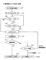
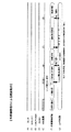
図2は、本実施形態の外部接続機器3のカメラ本体に対する再起動処理(初期化処理)を示すフローチャートである。 FIG. 2 is a flowchart showing a restart process (initialization process) for the camera body of the externally connected device 3 according to this embodiment.
CPU32は、カメラ初期化要求があると(ST1)、タイマをスタートさせて8ST2)、待ち時間Twaitが時間Llimit を超えたか否かを判別を行う(ST3)。
ステップST3において、待ち時間Twaitが時間Llimit を超えたと判別したば場合には、カメラ本体2から信号ライン43を通して転送されてきた信号CAM POWERがオンであるかオフであるか判別を行う(ST4)。
ステップST4において、信号CAM POWERがオンであると判別した場合には、ステップST3からの処理に戻る。
一方、ステップST4において、信号CAM POWERがオフであると判別した場合、あるいはステップST3において、待ち時間Twaitが時間Llimit を超えていないと判別した場合には、リセット信号RESETを端子34を通して信号ライン44に転送してカメラ本体2を第1の動作モードに遷移させて再起動(初期化)させる(ST5)。
そして、一定時間待った後(ST6)、信号ライン46を通してカメラ本体2との通信確認を行う(ST7)。
そして、通信が正常(OK)である場合、カメラ初期化を正常終了する(ST)。
通信が正常でない(NG)場合、あらかじめ設定したリトライ回数だけ、ステップST5からの処理を繰り返し(ST9)、リトライ回数だけリセット処理を行っても通信が正常でない場合にはカメラ初期化エラーとして処理する(ST10)。
When there is a camera initialization request (ST1), the
If it is determined in step ST3 that the waiting time Twait has exceeded the time Llimit, the signal CAM transferred from the camera body 2 through the
In step ST4, the signal CAM If it is determined that POWER is on, the process returns to step ST3.
On the other hand, in step ST4, the signal CAM When it is determined that POWER is off, or when it is determined in step ST3 that the waiting time Twait does not exceed the time Llimit, the reset signal RESET is transferred to the
Then, after waiting for a certain time (ST6), communication with the camera body 2 is confirmed through the signal line 46 (ST7).
If the communication is normal (OK), camera initialization ends normally (ST).
If the communication is not normal (NG), the process from step ST5 is repeated for the preset number of retries (ST9), and if the communication is not normal even if the reset process is performed for the number of retries, it is processed as a camera initialization error. (ST10).
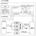
図3は、カメラ本体の状態遷移を示す図である。 FIG. 3 is a diagram illustrating state transition of the camera body.
図3の例では、制御信号BOX SETとDC INのオン、オフに応じたカメラ本体2の状態遷移例を示している。 In the example of FIG. 3, the control signal BOX SET and DC An example of the state transition of the camera body 2 in response to IN on / off is shown.
カメラリセット時に、制御信号BOX SETとDC INが共にオフの場合には、「POWER_OFF」状態へ遷移する。この場合、第1CPU25は電源は供給されているが、省電力モードの状態となり、第2CPU26はオフ(OFF)となる。
カメラリセット時に、制御信号BOX SETがオフで、DC INがオンの場合には、「POWER_OFF(充電)」状態へ遷移する。この場合、第1CPU25は充電回路23を制御し、バッテリーを充電する。第2CPU26はオフ状態となる。
カメラリセット時に、制御信号BOX SETがオンの場合、CAM POWER ONとなり、第2CPU26および機能ブロック27に電源が供給される。
At camera reset, control signal BOX SET and DC When both IN are off, the state transits to the “POWER_OFF” state. In this case, the
At camera reset, control signal BOX SET is off and DC When IN is on, the state transits to a “POWER_OFF (charge)” state. In this case, the
At camera reset, control signal BOX CAM when SET is on POWER The power is turned on and power is supplied to the
カメラリセット時に、「POWER_OFF」状態または「POWER_OFF(充電)」状態に遷移した場合でも、パワーキーがオンされることで、第2CPU26および機能ブロック27に電源が供給される。
第2CPU26は、電源オン状態となることによって、それぞれ条件に応じて次のいずれかのカメラ動作をする。
Even when the camera is reset, the power key is turned on even when the state transits to the “POWER_OFF” state or the “POWER_OFF (charge)” state, whereby power is supplied to the
The
CAMERA_MODE:通常カメラ動作のモード。
PLAY_MODE:記録した画像を再生するモード。
SET_UP_MODE:カメラの各種設定を行うモード。
EXT_MODE:外部接続機器3が接続されたときのモードであり、外部接続機器3からの命令のみで動作し、カメラのスイッチ操作等は受け付けない。
CAMERA_MODE: Normal camera operation mode.
PLAY_MODE: Mode for playing back recorded images.
SET_UP_MODE: Mode for performing various camera settings.
EXT_MODE: Mode when the externally connected device 3 is connected, operates only with commands from the externally connected device 3, and does not accept camera switch operations or the like.
パワーキーオフ等、パワーオフ要求が生じた場合、第2CPU26は処理中の動作が完了し次第、第1CPU25に対してパワーオフの要求を出す。
第1CPU25は、第2CPU26からのパワーオフ要求を受けて第2CPU26の電源をオフするように制御する。
外部接続機器3が接続されたときの第1の動作モード(EXT MODE)にある場合、外部接続機器3から外されたことを示す、BOX SET=OFFが検知された場合か外部接続機器3からパワーオフの要求を受けた場合にパワーオフ処理に遷移する。
外部接続機器3が接続されていないときの第2の動作モード(EXT MODE以外)にある場合、通常のパワーキーのオフ等でパワーオフ要求が発生するが、外部接続機器3が接続された場合、すなわち信号BOX SETのオンを検知した場合もパワーオフ要求を発生させ、パワーオフ状態へ遷移する。これにより、外部接続機器3からのリセット処理を受けられる状態とする。
When a power off request such as power key off occurs, the
The
The first operation mode (EXT) when the external device 3 is connected BOX indicating that it has been removed from the external connection device 3 When SET = OFF is detected or when a power-off request is received from the external device 3, the process proceeds to the power-off process.
Second operation mode (EXT) when the external device 3 is not connected When the external connection device 3 is connected, that is, the signal BOX is generated. Even when SET ON is detected, a power-off request is generated and a transition to the power-off state is made. Thereby, it will be in the state which can receive the reset process from the external connection apparatus 3. FIG.
以下に、外部接続機器3が、カメラ本体2に接続される場合の動作を、カメラがオン状態で接続された場合、カメラ本体2がファイル書き込み中等のビジー(BUSY)中で接続された場合、カメラ本体2がハングアップ中に外部接続機器3により起動要求された場合、並びに、外部接続機器3による遠隔操作による撮影動作を、図面に関連付けて説明する。 The operation when the externally connected device 3 is connected to the camera body 2 is as follows: when the camera is connected in an on state, when the camera body 2 is connected during busy (BUSY) such as writing a file, A case where the activation request is issued by the external connection device 3 while the camera body 2 is hung up, and a photographing operation by remote operation by the external connection device 3 will be described with reference to the drawings.
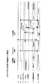
まず、図4(A)〜(G)に関連付けて、カメラ本体2がオン状態で接続された場合の動作を説明する。
なお、図4(A)がDC INを、図4(B)が制御信号BOX SETを、図4(C)が信号CAM POWERを、図4(D)がリセット信号RESETを、図4(E)が信号ライン36を通してのUSB通信を、図4(F)が外部接続機器3の状態を、図4(G)がカメラ本体2の状態をそれぞれ示している。
First, the operation when the camera body 2 is connected in the on state will be described with reference to FIGS.
4A shows DC. IN, FIG. 4B shows the control signal BOX FIG. 4C shows the signal CAM. 4D shows the reset signal RESET, FIG. 4E shows the USB communication through the signal line 36, FIG. 4F shows the state of the external device 3, and FIG. 4G shows the camera. The state of the main body 2 is shown respectively.
外部接続機器3は、スイッチ3をオンすることで外部接続機器3のCPU32が処理か処理を実行した後、待機状態となる。そこへカメラ本体2がオン状態で外部接続機器3に接続された場合、カメラ本体2はBOS SET信号を検知してパワーオフ処理を実行する。すなわち、第2CPU26がパワーオフ要求を発生させ、それを受けて、第1CPU25が、第2CPU26および機能ブロック27への電源供給をオフする。これにより、信号CAM POWERもオフとなる。このとき、外部接続機器3が接続されているので、電圧DC INの供給が検知され、第1CPU25は充電回路を制御し、カメラ本体2は「POWER OFF(充電)」状態に遷移する。
外部接続機器3においてカメラ起動要求が発生した場合、CMA POWERの状態をチェックし、オフとなっていることを確認した後、一定のウェイト時間の後、リセット信号RESETを端子T34を通して信号ライン44に転送してカメラ本体2を再起動(リセット)させ、第1の動作モードに遷移させる。
外部接続機器3では、図2に示すようなリセット(初期化処理)が終了すると、一定時間待った後、初期化通信が行われる。
この一定時間のウェイト時間の間に、カメラ本体2は処理化処理の後、制御信号BOX SETに基づいてEXT_MODEとなり、外部接続機器3からの命令のみで動作し、カメラのスイッチ操作等は受け付けない状態となる。
The externally connected device 3 enters a standby state after the
When a camera activation request occurs in the external connection device 3, CMA After checking the POWER state and confirming that it is off, after a certain wait time, the reset signal RESET is transferred to the
In the externally connected device 3, when reset (initialization processing) as shown in FIG. 2 is completed, initialization communication is performed after waiting for a predetermined time.
During this waiting time, the camera body 2 performs the control signal BOX after processing. EXT_MODE is set based on SET, and only the command from the external device 3 operates, and the camera switch operation or the like is not accepted.
次に、図5(A)〜(G)に関連付けて、カメラ本体がファイル書き込み中等のビジー(BUSY)中に接続された場合の動作を説明する。
なお、図5(A)がDC INを、図5(B)が制御信号BOX SETを、図5(C)が信号CAM POWERを、図5(D)がリセット信号RESETを、図5(E)が信号ライン36を通してのUSB通信を、図5(F)が外部接続機器3の状態を、図5(G)がカメラ本体2の状態をそれぞれ示している。
Next, the operation when the camera body is connected during busy (BUSY) such as writing a file will be described with reference to FIGS.
5A shows DC. IN, FIG. 5B shows the control signal BOX FIG. 5C shows the signal CAM. FIG. 5D shows the reset signal RESET, FIG. 5E shows the USB communication through the signal line 36, FIG. 5F shows the state of the external connection device 3, and FIG. 5G shows the camera. The state of the main body 2 is shown respectively.
カメラ本体2がオン状態で外部接続機器3が接続された場合、外部接続機器3は図5(F)に示すように、待機状態にある。このとき、カメラ本体2がCAMERA MODEの状態にあり、かつファイル書き込み中であった場合、カメラ本体2の状態報知信号CAM POWERがオンであることを検知し、外部接続機器3はカメラ本体2がビジー(BUSY)状態であることを認識し、ウェイト状態となる。
このウェイト状態では、外部接続機器3が一定時間おきに信号CAM POWERの状態をチェックする。
カメラ本体2は、ファイル書き込みが終了し次第、制御信号BOS SETのオンを受けて、パワーオフ処理に移行し、その後「POWER OFF(充電)」状態に遷移する。
外部接続機器3においてカメラ起動要求が発生した場合は、信号CAM POWERの状態をチェックし、オフとなっていることを確認した後、一定のウェイト時間の後、リセット信号RESETを端子T34を通して信号ライン44に転送してカメラ本体2を再起動(リセット)させ、第1の動作モードに遷移させる。
外部接続機器3では、図2に示すようなリセット(初期化)処理が終了すると、一定時間待った後、初期化通信が行われる。
この一定時間のウェイト時間の間に、カメラ本体2は処理化処理の後、制御信号BOX SETに基づいてEXT_MODEとなり、外部接続機器3からの命令のみで動作し、カメラのスイッチ操作等は受け付けない状態となる。
When the external connection device 3 is connected while the camera body 2 is on, the external connection device 3 is in a standby state as shown in FIG. At this time, the camera body 2 is CAMERA. If the camera is in the MODE state and the file is being written, the state notification signal CAM of the camera body 2 When it is detected that POWER is on, the external device 3 recognizes that the camera body 2 is in a busy state and enters a wait state.
In this wait state, the externally connected device 3 makes a signal CAM at regular intervals. Check the status of POWER.
The camera body 2 controls the control signal BOS as soon as the file writing is completed. When SET is turned on, the process proceeds to power-off processing. Transition to the “OFF (charge)” state.
When a camera activation request occurs in the external connection device 3, the signal CAM After checking the POWER state and confirming that it is off, after a certain wait time, the reset signal RESET is transferred to the
In the externally connected device 3, when the reset (initialization) process as shown in FIG. 2 is completed, initialization communication is performed after waiting for a predetermined time.
During this waiting time, the camera body 2 performs the control signal BOX after processing. EXT_MODE is set based on SET, and only the command from the external device 3 operates, and the camera switch operation or the like is not accepted.
次に、図6(A)〜(G)に関連付けて、カメラ本体2がハングアップ中に外部接続機器3により起動要求された場合の動作を説明する。
なお、図6(A)がDC INを、図6(B)が制御信号BOX SETを、図6(C)が信号CAM POWERを、図6(D)がリセット信号RESETを、図6(E)が信号ライン36を通してのUSB通信を、図6(F)が外部接続機器3の状態を、図6(G)がカメラ本体2の状態をそれぞれ示している。
Next, with reference to FIGS. 6A to 6G, an operation when the activation request is issued by the external connection device 3 while the camera body 2 is hung up will be described.
Note that FIG. 6A shows DC. IN, FIG. 6B shows the control signal BOX FIG. 6C shows the signal CAM. 6D shows the reset signal RESET, FIG. 6E shows the USB communication through the signal line 36, FIG. 6F shows the state of the external connection device 3, and FIG. 6G shows the camera. The state of the main body 2 is shown respectively.
カメラ本体2がオン状態で外部接続機器3が接続された場合、外部接続機器3は図5(F)に示すように、待機状態にあり、カメラ本体2は何らかの要因により、ハングアップ状態にあり、外部接続機器3は、ウェイト状態とある。
このとき、外部接続機器3においてカメラ起動要求が発生した場合、信号CAM POWERの状態チェックを開始する。外部接続機器3は一定時間おきに信号CAM POWERをチェックするが、カメラ本体2はハングアップ状態が解消されないことから、外部接続機器3ではタイムアウトとして検出し、リセット信号RESETを端子T34を通して信号ライン44に転送してカメラ本体2を再起動(リセット)させ、第1の動作モードに遷移させる。
外部接続機器3では、図2に示すようなリセット(初期化)処理が終了すると、一定時間待った後、初期化通信が行われる。
この一定時間のウェイト時間の間に、カメラ本体2は処理化処理の後、制御信号BOX SETに基づいてEXT_MODEとなり、外部接続機器3からの命令のみで動作し、カメラのスイッチ操作等は受け付けない状態となる。
When the external connection device 3 is connected while the camera body 2 is on, the external connection device 3 is in a standby state as shown in FIG. 5F, and the camera body 2 is in a hang-up state due to some factor. The externally connected device 3 is in a wait state.
At this time, if a camera activation request is generated in the external device 3, the signal CAM The POWER status check is started. The externally connected device 3 receives the signal CAM at regular intervals. Although POWER is checked, the hang-up state of the camera body 2 is not resolved. Therefore, the external connection device 3 detects a timeout, transfers the reset signal RESET to the
In the externally connected device 3, when the reset (initialization) process as shown in FIG. 2 is completed, initialization communication is performed after waiting for a predetermined time.
During this waiting time, the camera body 2 performs the control signal BOX after processing. EXT_MODE is set based on SET, and only the command from the external device 3 operates, and the camera switch operation or the like is not accepted.
次に、図7(A)〜(G)に関連付けて、外部接続機器3による遠隔操作による撮影動作を説明する。
なお、図7(A)がDC INを、図7(B)が制御信号BOX SETを、図7(C)が信号CAM POWERを、図7(D)がリセット信号RESETを、図7(E)が信号ライン36を通してのUSB通信を、図7(F)が外部接続機器3の状態を、図7(G)がカメラ本体2の状態をそれぞれ示している。
Next, a photographing operation by remote operation by the external connection device 3 will be described with reference to FIGS.
Note that FIG. 7A shows DC. IN, FIG. 7B shows the control signal BOX FIG. 7C shows the signal CAM. 7D shows the reset signal RESET, FIG. 7E shows the USB communication through the signal line 36, FIG. 7F shows the state of the externally connected device 3, and FIG. 7G shows the camera. The state of the main body 2 is shown respectively.
この場合、カメラ本体2は、外部接続機器3からの通信以外、カメラのスイッチ等を受け付けないEXT_MODEとなっている。
そして、信号ライン36を通して外部接続機器3側からレンズ繰り出し要求、撮影要求が発行される。カメラ本体2は、信号ライン36を通して外部接続機器3側からレンズ繰り出し要求、撮影要求に応じて動作を行う。
上記実施形態において、外部接続機器3に電子機器の動作状態を報知する状態報知手段について、カメラの電源状態を示す信号CAM POWERを用いて、カメラの電源オンオフを報知する状態報知手段を一例としてあげたが、信号ライン36を通してのUSB通信を用いることも可能である。この場合、電源のオンオフだけでなく、ファイルの書き込み中、撮影中等を区別して送信することで外部接続機器3がより細かいカメラの動作状態を判断することができる。
In this case, the camera body 2 is set to EXT_MODE that does not accept camera switches other than communication from the externally connected device 3.
Then, a lens extension request and a photographing request are issued from the external device 3 side through the signal line 36. The camera body 2 operates in response to a lens extension request and a photographing request from the external connection device 3 side through the signal line 36.
In the above embodiment, the signal CAM indicating the power supply state of the camera for the state notification means for notifying the external connection device 3 of the operation state of the electronic device. As an example, the state informing means for informing the power on / off of the camera using POWER is given, but USB communication through the signal line 36 can also be used. In this case, the externally connected device 3 can determine a finer operating state of the camera by not only turning on / off the power but also transmitting while distinguishing between writing a file and shooting.
以上説明したように、本実施形態によれば、カメラ本体2に外部接続機器3からの操作のみ受け付ける特殊なモードを用意し、外部接続機器3か接続された場合、外部接続機器3からのカメラハードリセットによるリセット動作からのみこのモードに遷移するようにすることでこの複雑な状態管理を単純化することができる。
また、なんらかの理由により、カメラ本体2がハングアップ等を起こし、外部接続機器3からの通信を受け付けなくなってしまった状態でも、外部接続機器3からこのハードリセットをかけることによって確実にリカバリー動作をすることができる。特に外部接続機器3を遠隔操作するような場合、カメラ本体2がハングアップしたりすると、通常はカメラのあるところまで行き、リカバリー動作させなければならないが、このような仕組みとすることで、カメラから離れた場所にいても確実に外部接続機器3を通じてリカバリー動作が実現できるため、より信頼性の高いシステムを実現することができる。
このカメラ本体2を、通常は外部接続機器3との接続をせず、通常のカメラとして使用するようなシ ステムでは、ユーザーがカメラの状態を気にすることなく自由に着脱を行っても問題ないようにする必要がある。
外部接続機器3がカメラ側のハードリセットをかけるこのシステムにおいては、例えばカメラが記憶媒体のデータを読み込んでいたり、書き込んでいたりしている最中に外部接続機器3と接続し、これを受けて外部接続機器3がハードリセットをかけてしまうと、記憶媒体のデータもしくは記憶媒体そのものを壊してしまう可能性もある。
本実施形態においては、外部接続機器3がカメラの状態を見てハードリセットをかけるかどうかを判断することにより、そのような不具合も防止することによって、ユーザーの使い勝手を向上させることができる。
As described above, according to the present embodiment, a special mode for accepting only an operation from the external connection device 3 is prepared in the camera body 2, and the camera from the external connection device 3 is connected when the external connection device 3 is connected. This complicated state management can be simplified by making a transition to this mode only from a reset operation by a hard reset.
Even if the camera body 2 hangs up for some reason and communication from the external connection device 3 is not accepted, the recovery operation is surely performed by applying this hard reset from the external connection device 3. be able to. Especially when the external device 3 is operated remotely, if the camera body 2 hangs up, it is usually necessary to go to the place where the camera is and perform a recovery operation. Since the recovery operation can be surely realized through the external connection device 3 even in a place away from the vehicle, a more reliable system can be realized.
In a system where the camera body 2 is not normally connected to the external connection device 3 and is used as a normal camera, it is not a problem that the user can freely attach and detach without worrying about the state of the camera. It is necessary not to.
In this system in which the externally connected device 3 performs a hard reset on the camera side, for example, the camera is connected to the externally connected device 3 while the camera is reading or writing data on the storage medium. If the external connection device 3 is subjected to a hard reset, there is a possibility that the data of the storage medium or the storage medium itself is destroyed.
In the present embodiment, the user-friendliness can be improved by preventing such a problem by determining whether or not the external connection device 3 performs a hard reset by looking at the state of the camera.
1…遠隔操作カメラシステム、2…カメラ本体、21…被接続部、22…電池、23…切替/充電回路、24…電源回路、25…第1CPU、26…第2CPU,3…外部接続機器、31…スイッチ、32…CPU。
DESCRIPTION OF
Claims (11)
少なくとも上記接続機器からの再起動の指令を受ける、上記接続機器との信号の送受を行う信号ラインと、
上記接続機器の接続を検知する検知手段と、
上記信号ラインの信号からの再起動の指令に基づき再起動を行う再起動手段と、
上記再起動手段による再起動の際、上記検知手段により上記接続機器の接続が検知された場合には上記第1のアプリケーションプログラムで起動を行って上記第1の動作モードに遷移し、上記検出手段により上記接続機器の非接続が検知された場合には上記第2のアプリケーションプログラムで起動を行って上記第2の動作モードに遷移する第1の制御手段と
を有する電子機器。 A first operation mode that can be connected to a connection device and is used in a connected state with at least the connection device, and a second operation mode that is used in a non-connection state with the connection device, and at least a first operation mode An electronic device capable of executing a first application program corresponding to the second application program and a second application program corresponding to the second operation mode,
At least a signal line for receiving and receiving a restart command from the connected device, for transmitting and receiving signals to and from the connected device,
Detection means for detecting connection of the connection device;
Restarting means for restarting based on a restart command from the signal of the signal line;
At the time of restarting by the restarting means, if the connection of the connected device is detected by the detecting means, the first application program starts up and transitions to the first operation mode, and the detecting means And a first control unit that is activated by the second application program and transitions to the second operation mode when it is detected that the connection device is disconnected.
請求項1に記載の電子機器。 The electronic device according to claim 1, further comprising: a state notification unit that notifies the connection device of an operation state through the signal line when the connection of the connection device is detected by the detection unit.
請求項2記載の電子機器。 The electronic device according to claim 2, wherein the first control unit notifies the connection device of an operation state by the state notification unit, and restricts restart from the connection device according to the notified operation state.
上記第1の制御手段は、パワーオン状態で、上記検知手段により上記接続機器の接続を検知すると、一旦パワーオフ処理を行って上記外部電源による充電処理を行い、
再起動手段は、上記信号ラインの信号からの再起動の指令に基づき再起動を行う
請求項1乃至3のいずれか一に記載の電子機器。 The signal line includes a signal line connected to an external power source,
When the first control means detects the connection of the connected device by the detection means in a power-on state, the first control means performs a power-off process once and performs a charging process by the external power source,
The electronic device according to any one of claims 1 to 3, wherein the restarting unit restarts based on a restart command from the signal on the signal line.
上記第1の制御手段は、上記第2の動作モードの特定の状態で、上記検知手段により上記接続機器の接続を検知すると、当該第2の動作モードの特定の状態が解除されてから、一旦パワーオフ処理を行って上記外部電源による充電処理を行い、
再起動手段は、上記信号ラインの信号からの再起動の指令に基づき再起動を行う
請求項1乃至4のいずれか一に記載の電子機器。 The signal line includes a signal line connected to an external power source,
When the detection unit detects the connection of the connected device in the specific state of the second operation mode, the first control unit temporarily releases the specific state of the second operation mode. Perform a power-off process to charge the external power supply,
The electronic device according to any one of claims 1 to 4, wherein the restarting unit restarts based on a restart command from the signal of the signal line.
請求項1乃至5のいずれか一に記載の電子機器。 The electronic device according to any one of claims 1 to 5, wherein when a control signal is supplied from the first control unit and the connection device, state transition is performed according to the control signal.
上記電子機器へ再起動の指令を送るための再起動指令手段と、
少なくとも上記再起動指令手段からの再起動指令を送ると共に上記電子機器の動作状態の報知を受ける、上記電子機器との信号の送受を行う信号ラインと、
上記信号ラインから受けた上記電子機器の動作状態の報知により当該電子機器の状態を検知する状態検知手段と、
上記状態検知手段により上記電子機器の動作状態が上記第2の動作モードにおける特定の状態の場合、上記再起動指令手段による再起動の指令を制限して上記電子機器の動作状態を上記特定の状態に維持させ、上記電子機器の動作状熊が上記特定の状態でない場合、上記再起動指令手段による再起動を実施し上記電子機器を第1の動作モードで再起動させる第2の制御手段と
を有する接続機器。 A connection device connectable to an electronic device having at least a first operation mode used in a connected state and a second operation mode used in a non-connected state,
A restart command means for sending a restart command to the electronic device;
Sending a restart command from at least the restart command means and receiving notification of the operating state of the electronic device, a signal line for transmitting and receiving signals with the electronic device,
State detection means for detecting the state of the electronic device by notifying the operation state of the electronic device received from the signal line;
When the operation state of the electronic device is a specific state in the second operation mode by the state detection means, the restart command by the restart command means is limited to change the operation state of the electronic device to the specific state. And when the operation bear of the electronic device is not in the specific state, a second control unit that performs restart by the restart command unit and restarts the electronic device in the first operation mode; Having connected equipment.
請求項7に記載の接続機器。 When the operation state of the electronic device is a specific state in the second operation mode by the state detection unit, the second control unit waits for detection of power off by the state detection unit, and then restarts the restart command. The connection device according to claim 7, wherein the electronic device is restarted in a first operation mode by performing restart by means.
請求項7に記載の接続機器。 When the operation state of the electronic device is a specific state in the second operation mode by the state detection unit, the second control unit restricts a restart command by the restart command unit and controls the electronic device. The operation state is maintained at the specific state, and after the power detection is detected by the state detection unit, the electronic device is restarted in the first operation mode by restarting the restart command unit. The connection device according to claim 7.
上記接続機器と接続可能で、少なくとも上記接続機器と接続状態で用いられる第1の動作モードと、上記接続機器と非接続状態で用いられる第2の動作モードとを有し、少なくとも第1の動作モードに対応した第1のアプリケーションプログラムと第2の動作モードに対応した第2のアプリケーションプログラムとを実行可能な電子機器と、を有し、
上記電子機器は、
少なくとも上記接続機器からの再起動の指令を受ける、上記接続機器との信号の送受を行う信号ラインと、
上記接続機器の接続を検知する検知手段と、
上記信号ラインの信号からの再起動の指令に基づき再起動を行う再起動手段と、
上記再起動手段による再起動の際、上記検知手段により上記接続機器の接続が検知された場合には上記第1のアプリケーションプログラムで起動を行って上記第1の動作モードに遷移し、上記検出手段により上記接続機器の非接続が検知された場合には上記第2のアプリケーションプログラムで起動を行って上記第2の動作モードに遷移する第1の制御手段と、を含み、
上記接続機器は、
上記電子機器へ再起動の指令を送るための再起動指令手段と、
少なくとも上記再起動指令手段からの再起動指令を送ると共に上記電子機器の動作状態の報知を受ける、上記電子機器との信号の送受を行う信号ラインと、
上記信号ラインから受けた上記電子機器の動作状態の報知により当該電子機器の状態を検知する状態検知手段と、
上記状態検知手段により上記電子機器の動作状態が上記第2の動作モードにおける特定の状態の場合、上記再起動指令手段による再起動の指令を制限して上記電子機器の動作状態を上記特定の状態に維持させ、上記電子機器の動作状熊が上記特定の状態でない場合、上記再起動指令手段による再起動を実施し上記電子機器を第1の動作モードで再起動させる第2の制御手段と、を含む
遠隔操作システム。 Connected equipment,
A first operation mode that can be connected to the connection device and used in a connected state with at least the connection device, and a second operation mode that is used in a non-connection state with the connection device, and has at least a first operation. An electronic device capable of executing a first application program corresponding to the mode and a second application program corresponding to the second operation mode,
The electronic device
At least a signal line for receiving and receiving a restart command from the connected device, for transmitting and receiving signals to and from the connected device,
Detection means for detecting connection of the connection device;
Restarting means for restarting based on a restart command from the signal of the signal line;
At the time of restarting by the restarting means, if the connection of the connected device is detected by the detecting means, the first application program starts up and transitions to the first operation mode, and the detecting means And a first control means for starting up with the second application program and transitioning to the second operation mode when non-connection of the connection device is detected.
The connected devices are
A restart command means for sending a restart command to the electronic device;
Sending a restart command from at least the restart command means and receiving notification of the operating state of the electronic device, a signal line for transmitting and receiving signals with the electronic device,
State detection means for detecting the state of the electronic device by notifying the operation state of the electronic device received from the signal line;
When the operation state of the electronic device is a specific state in the second operation mode by the state detection means, the restart command by the restart command means is limited to change the operation state of the electronic device to the specific state. And when the operation state bear of the electronic device is not in the specific state, a second control unit that performs restart by the restart command unit and restarts the electronic device in the first operation mode; Including remote control system.
上記電子機器に上記接続機器を接続し、
上記電子機器の動作状態を上記接続機器に報知し、
上記電子機器の動作状態が上記第2の動作モードにおける特定の状態の場合、再起動の指令を制限して上記電子機器の動作状態を上記特定の状態に維持させ、
上記電子機器の動作状熊が上記特定の状態でない場合、上記接続機器から電子機器の再起動を実施し上記電子機器を第1の動作モードで再起動させる
遠隔操作方法。
A first operation mode that can be connected to a connection device and is used in a connected state with at least the connection device, and a second operation mode that is used in a non-connection state with the connection device, and at least a first operation mode A remote operation method for remotely operating an electronic device capable of executing a first application program corresponding to the second application program and a second application program corresponding to the second operation mode, using the connection device,
Connect the connection device to the electronic device,
Notifying the connected device of the operating state of the electronic device,
When the operation state of the electronic device is a specific state in the second operation mode, the restart command is limited to maintain the operation state of the electronic device in the specific state,
The remote operation method of restarting the electronic device from the connected device and restarting the electronic device in the first operation mode when the operation state bear of the electronic device is not in the specific state.
Priority Applications (1)
| Application Number | Priority Date | Filing Date | Title |
|---|---|---|---|
| JP2004304877A JP4624757B2 (en) | 2004-10-19 | 2004-10-19 | Electronic device, connection device, remote operation system, and remote operation method |
Applications Claiming Priority (1)
| Application Number | Priority Date | Filing Date | Title |
|---|---|---|---|
| JP2004304877A JP4624757B2 (en) | 2004-10-19 | 2004-10-19 | Electronic device, connection device, remote operation system, and remote operation method |
Publications (2)
| Publication Number | Publication Date |
|---|---|
| JP2006121237A true JP2006121237A (en) | 2006-05-11 |
| JP4624757B2 JP4624757B2 (en) | 2011-02-02 |
Family
ID=36538736
Family Applications (1)
| Application Number | Title | Priority Date | Filing Date |
|---|---|---|---|
| JP2004304877A Expired - Fee Related JP4624757B2 (en) | 2004-10-19 | 2004-10-19 | Electronic device, connection device, remote operation system, and remote operation method |
Country Status (1)
| Country | Link |
|---|---|
| JP (1) | JP4624757B2 (en) |
Cited By (4)
| Publication number | Priority date | Publication date | Assignee | Title |
|---|---|---|---|---|
| JP2009065410A (en) * | 2007-09-06 | 2009-03-26 | Sanyo Electric Co Ltd | Image compression circuit and digital camera |
| JP2014127065A (en) * | 2012-12-27 | 2014-07-07 | Canon Inc | Image processing device, system, control method and program |
| JP2016092665A (en) * | 2014-11-07 | 2016-05-23 | 志 儒 洪 | Electric circuit changing operational function of load by stopping power supply temporarily |
| JP2024170213A (en) * | 2023-05-26 | 2024-12-06 | 村田機械株式会社 | Terminal device and method for restarting terminal device |
Citations (1)
| Publication number | Priority date | Publication date | Assignee | Title |
|---|---|---|---|---|
| JPS57127979A (en) * | 1981-01-30 | 1982-08-09 | Canon Inc | Video system |
-
2004
- 2004-10-19 JP JP2004304877A patent/JP4624757B2/en not_active Expired - Fee Related
Patent Citations (1)
| Publication number | Priority date | Publication date | Assignee | Title |
|---|---|---|---|---|
| JPS57127979A (en) * | 1981-01-30 | 1982-08-09 | Canon Inc | Video system |
Cited By (5)
| Publication number | Priority date | Publication date | Assignee | Title |
|---|---|---|---|---|
| JP2009065410A (en) * | 2007-09-06 | 2009-03-26 | Sanyo Electric Co Ltd | Image compression circuit and digital camera |
| JP2014127065A (en) * | 2012-12-27 | 2014-07-07 | Canon Inc | Image processing device, system, control method and program |
| JP2016092665A (en) * | 2014-11-07 | 2016-05-23 | 志 儒 洪 | Electric circuit changing operational function of load by stopping power supply temporarily |
| JP2024170213A (en) * | 2023-05-26 | 2024-12-06 | 村田機械株式会社 | Terminal device and method for restarting terminal device |
| JP7897553B2 (en) | 2023-05-26 | 2026-07-30 | 村田機械株式会社 | Terminal device and method for restarting the terminal device |
Also Published As
| Publication number | Publication date |
|---|---|
| JP4624757B2 (en) | 2011-02-02 |
Similar Documents
| Publication | Publication Date | Title |
|---|---|---|
| JP3654274B2 (en) | Data transfer control device, electronic device, and power supply switching method | |
| US20080162955A1 (en) | Usb host, usb device, and methods of controlling the host and the device | |
| JPWO2005001701A1 (en) | Slave device, communication setting method | |
| JPH1173247A (en) | I / O card, electronic device, electronic system, and method of starting electronic device | |
| JP5089415B2 (en) | Peripheral device, control method thereof and program | |
| US9294633B2 (en) | Communication control apparatus and method for controlling the same | |
| EP2499813A1 (en) | Camera system | |
| JP3675394B2 (en) | Communication device | |
| JP2001067156A (en) | Computer peripheral device, control method therefor, imaging apparatus, and storage medium | |
| JP2001067156A5 (en) | Computer peripherals and their control methods, imaging devices and their control methods, and computer-readable storage media | |
| JP4624757B2 (en) | Electronic device, connection device, remote operation system, and remote operation method | |
| US7535490B2 (en) | Imaging apparatus having control modes switchable based on connection to another apparatus | |
| JP2006059088A (en) | Data transfer control system, electronic device and program | |
| JP2002108518A (en) | Peripheral device and method for controlling the same | |
| JP3927874B2 (en) | Image processing apparatus, control method therefor, program, and storage medium | |
| JP4870098B2 (en) | Electronic device and control method of electronic device | |
| JP2005244633A (en) | Cradle | |
| JP7387420B2 (en) | Accessory devices, imaging devices, and control methods | |
| JP4262534B2 (en) | Digital equipment | |
| JP3679513B2 (en) | camera | |
| JP2012147357A (en) | Imaging apparatus | |
| JP4681937B2 (en) | Imaging apparatus and imaging method | |
| JP2009060602A (en) | Imaging device | |
| JPH11288338A (en) | USB controller and device equipped with the same | |
| JP3890346B2 (en) | camera |
Legal Events
| Date | Code | Title | Description |
|---|---|---|---|
| A621 | Written request for application examination |
Free format text: JAPANESE INTERMEDIATE CODE: A621 Effective date: 20070907 |
|
| A131 | Notification of reasons for refusal |
Free format text: JAPANESE INTERMEDIATE CODE: A131 Effective date: 20100622 |
|
| A521 | Request for written amendment filed |
Free format text: JAPANESE INTERMEDIATE CODE: A523 Effective date: 20100823 |
|
| TRDD | Decision of grant or rejection written | ||
| A01 | Written decision to grant a patent or to grant a registration (utility model) |
Free format text: JAPANESE INTERMEDIATE CODE: A01 Effective date: 20101005 |
|
| A01 | Written decision to grant a patent or to grant a registration (utility model) |
Free format text: JAPANESE INTERMEDIATE CODE: A01 |
|
| A61 | First payment of annual fees (during grant procedure) |
Free format text: JAPANESE INTERMEDIATE CODE: A61 Effective date: 20101104 |
|
| R150 | Certificate of patent or registration of utility model |
Free format text: JAPANESE INTERMEDIATE CODE: R150 |
|
| FPAY | Renewal fee payment (event date is renewal date of database) |
Free format text: PAYMENT UNTIL: 20131112 Year of fee payment: 3 |
|
| LAPS | Cancellation because of no payment of annual fees |